SteelBeast PRO 2 PB Series User manual


Contents
1. GENERAL INFORMATION............................................................................................... 3
1.1. Application................................................................................................................. 3
1.2. Technical data............................................................................................................ 3
1.3. Equipment included ................................................................................................... 4
1.4. Dimensions................................................................................................................ 5
1.5. Design ....................................................................................................................... 7
2. SAFETY PRECAUTIONS.................................................................................................. 8
3. STARTUP AND OPERATION..........................................................................................10
3.1. Installing the jaws and the jaw blocks........................................................................10
3.2. Installing the tool bits.................................................................................................12
3.3. Installing the motor....................................................................................................13
3.4. Clamping the machine into the pipe..........................................................................14
3.5. Preparing the air (for machine with air motor) ...........................................................15
3.6. Operating..................................................................................................................16
3.7. Troubleshooting the electric motor............................................................................18
3.8. Troubleshooting the battery motor.............................................................................18
4. ACCESSORIES...............................................................................................................19
4.1. Tool bits for carbon steel...........................................................................................19
4.2. Tool bits for stainless steel........................................................................................20
4.3. Air motor...................................................................................................................21
4.4. Electric motor............................................................................................................21
4.5. Battery motor ............................................................................................................21
4.6. Air preparation unit....................................................................................................22
4.7. 5.2 Ah battery ...........................................................................................................22
4.8. Battery charger .........................................................................................................22
4.9. Coolant .....................................................................................................................23
4.10. Small mandrel set ...................................................................................................23
4.11. Extension set ..........................................................................................................27
5. DECLARATION OF CONFORMITY.................................................................................28
6. WARRANTY CARD..........................................................................................................29

PB2
This document is protected by copyrights.
Copying, using, or distributing without permission of JEI Group Ltd is prohibited.
3
1. GENERAL INFORMATION
1.1. Application
The PRO 2 PB is a pipe bevelling machine designed to mill pipes made of carbon
and stainless steel, aluminum alloys, and copper-nickels. The machine can face and
bevel pipes from inner diameters (ID) of 22 mm (0.86″) to outer diameters (OD) of
48 mm (1.89″).
An optional small mandrel set allows you to bevel pipes from inner diameters of
15.5 mm (0.61″) to outer diameters of 29 mm (1.14″). An optional extension set
allows you to bevel pipes from inner diameters of 42 mm (1.65″) to outer diameters of
60.3 mm (2.37″).
1.2. Technical data
PRO 2 PB with
air motor
PRO 2 PB with
electric motor
PRO 2PB with
battery motor
Pressure
0.6 MPa (87 psi)
–
–
Voltage
–
1~ 220–240 V, 50–60 Hz
18 V DC, 5.2 Ah
Air motor
Modec
NT10RT0851FCA1F-CO
–
–
Electric motor
–
Metabo
SBEV 1100-2 S
Metabo
BS 18 LTX Impuls
Connection
CEJN 410 DN 10.4
R 1/2″BSPT fitting
for quick-coupling
Electrical plug
Battery socket
Air consumption
1400 l/min (50 CFM)
–
–
Power
800 W
1100 W
–
Pipe diameter
22 mm ID–48 mm OD
15.5 mm ID–29 mm OD*
42 mm ID–60.3 mm OD**
22 mm ID–48 mm OD
15.5 mm ID–29 mm OD*
42 mm ID–60.3 mm OD**
22 mm ID–48 mm OD
15.5 mm ID–29 mm OD*
42 mm ID–60.3 mm OD**
Maximum pipe wall thickness
8 mm
3.5 mm*
8 mm
3.5 mm*
8 mm
3.5 mm*
Rotational speed without load
210 rpm
10–134 rpm (gear 1)
30–377 rpm (gear 2)
10–60 rpm (gear 1)
30–205 rpm (gear 2)
Nominal rotational speed
105 rpm
10–134 rpm (gear 1)
30–377 rpm (gear 2)
10–60 rpm (gear 1)
30–205 rpm (gear 2)
Protection class
–
II
–
Required ambient temperature
0–40°C (34–104°F)
0–40°C (34–104°F)
0–40°C (34–104°F)
Weight with motor
7.6 kg (17 lbs)
7.4 kg (16.5 lbs)
6.5 kg (14.5 lbs),
includes battery
* With an optional small mandrel set (ZST-0567-20-00-00-0).
** With an optional extension set (ZST-0567-21-00-00-0).

PB2
This document is protected by copyrights.
Copying, using, or distributing without permission of JEI Group Ltd is prohibited.
4
1.3. Equipment included
1
Bevelling machine (without tool bits)
1 unit
2
Metal box
1 unit
3
Tool can
1 unit
4
Coolant container with nozzle
1 unit
5
2 sets of jaws (no. 4, 5), 3 sets of jaw blocks
(no. 6, 7, 8), and 5 sets of springs (no. 4, 5, 6,
7, 8) for standard mandrel
1 set
6
Spring gauge
1 unit
7
Handle
1 unit
8
4 mm hex wrench
1 unit
9
3 mm hex wrench
1 unit
10
24 mm flat wrench
2 units
11
Air motor
option
12
Electric motor
option
13
Battery motor
option
–
Operator’s Manual
1 unit
włącznika
(musi być ustawiony na R)
1
2
3
4
5
6
7
8
9
10
11
12
13

PB2
This document is protected by copyrights.
Copying, using, or distributing without permission of JEI Group Ltd is prohibited.
5
1.4. Dimensions
438 mm (17.2″)
64 mm (2.5″)
543 mm (21.4″)
513 mm (20.2″)
76 mm (3″)
438 mm (17.2″)
48 mm (1.9″)
48 mm (1.9″)

PB2
This document is protected by copyrights.
Copying, using, or distributing without permission of JEI Group Ltd is prohibited.
6
48 mm (1.9″)
373 mm (14.7″)
446 mm (17.6″)
83 mm (3.3″)

PB2
This document is protected by copyrights.
Copying, using, or distributing without permission of JEI Group Ltd is prohibited.
7
1.5. Design
Fig. 1.View of the machine with air motor and of the electric and battery motor
Feed knob
Tool bit holder
Air motor
ON/OFF lever
Air connection
ON switch lock
ON/OFF switch
Rotation direction switch
(must be set as shown)
Gear switch
Speed dial / LED
Rotation direction switch
(must be set as shown)
ON/OFF switch with
speed control
Gear switch
Torque dial
Battery
LED activation button
LED
Clamping knob
Operation mode switch
(must be set as shown)
Mandrel
Needle

PB2
This document is protected by copyrights.
Copying, using, or distributing without permission of JEI Group Ltd is prohibited.
8
2. SAFETY PRECAUTIONS
1. Before use, read this Operator’s Manual and complete a training in occupational
safety and health.
2. Use only motors specified in the technical data.
3. Use only in applications specified in this Operator’s Manual.
4. Make sure that the machine has all parts and they are genuine and not damaged.
5. Make sure that the specifications of the air (power) source are the same as those
specified on the rating plate.
6. Supply the machine with air motor only with clean and lubricated air. Make sure
that the air source has an air preparation unit that contains a filter, regulator, and
lubricator.
7. Do not pull the hose (cord). This can cause damage and serious injury.
8. Keep untrained bystanders away from the machine.
9. Before each use, ensure the correct condition of the machine, air (power) source,
supply hose (power cord, battery), coupling (plug), control parts, and tool bits.
10. Before each use, make sure that no part is cracked or loose. Make sure to
maintain correct conditions that can have an effect on the operation of the
machine.
11. Avoid accidental starts. Do not put the machine so that the motor will start. Do
not carry the machine with air motor by holding the ON/OFF lever.
12. Keep the machine dry. Do not expose the machine to rain, snow, or frost.
13. Keep the work area well-lit, clean, and free of obstacles.
14. Do not use machine near flammable materials, or in explosive environments.
15. Attach the pipe so that it will not fall or roll.
16. Use only tool bits specified in this Operator’s Manual.
17. Do not use tool bits that are dull or damaged.
18. Attach the tool bits with two set screws. Remove wrenches from the work area
before you connect the machine to the air (power) source.
19. Use eye and ear protection, protective footwear, and protective clothing. Do not
use loose clothing.
20. Use an electric/battery motor only after you set the rotation direction switch and
operation mode switch as shown in Fig. 1. Using left rotation or impulse mode
(switches set to the opposite positions) can damage the machine.

PB2
This document is protected by copyrights.
Copying, using, or distributing without permission of JEI Group Ltd is prohibited.
9
21. Do not touch chips or moving parts. Do not let anything catch in moving parts.
22. After each use, remove chips and coolant from the machine. Do not remove
chips with bare hands. Clean the machine with a cotton cloth and no chemical
agents.
23. Maintain the machine and install/remove parts and tool bits only after you unplug
the machine from the air (power) source or remove the battery.
24. Repair only in a service center appointed by the seller.
25. If the machine falls, is wet, or has any damage, stop the work and promptly send
the machine to the service center for check and repair.
26. Do not leave the machine when it operates.
27. If you are not going to use the machine, remove the tool bits from the sockets.
Then, remove the machine from the worksite and keep it in a safe and dry place.
28. If you are not going to use the machine for an extended period, put anti-corrosion
material on the steel parts.
PB2
This document is protected by copyrights.
Copying, using, or distributing without permission of JEI Group Ltd is prohibited.
10
3. STARTUP AND OPERATION
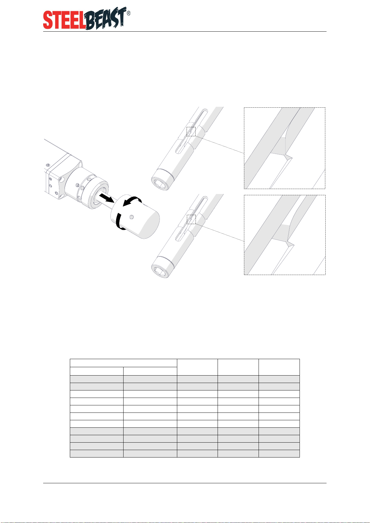
3.1. Installing the jaws and the jaw blocks
Retract the needle (1, 2, Fig. 2) and use a small wrench to align the needle socket
with the mandrel hole.
Fig. 2.Aligning the needle socket
Use a dry cloth to clean all needle sockets and mandrel holes. Lubricate them each
time before you install jaws and after each 50 work hours.
Use the table that follows to select the correct jaws, jaw blocks, and springs for
the diameter of the pipe. To see what the spring number is, put the spring on the
spring gauge.
Pipe inner diameter
Jaw
number
Jaw block
number
Spring
number
[mm]
[in]
15.5–19*
0.61–0.75
1
–
1
19–22*
0.75–0.86
2
–
2/4
22–26
0.86–1.02
4
–
2/4
26–30
1.02–1.18
5
–
5
30–34
1.18–1.34
5
6
6
34–38
1.34–1.49
5
7
7
38–42
1.49–1.65
5
8
8
42–46**
1.65–1.81
5
9
9
46–50**
1.81–1.97
5
10
10
50–54**
1.97–2.12
5
11
11
54–58**
2.12–2.28
5
12
12
* With an optional small mandrel set (ZST-0567-20-00-00-0)
** With an optional extension set (ZST-0567-21-00-00-0)
CORRECT
✓
INCORRECT
×
1
2

PB2
This document is protected by copyrights.
Copying, using, or distributing without permission of JEI Group Ltd is prohibited.
11
Put the jaws into the mandrel holes (1, Fig. 3). Make sure that the jaws are in the
holes. Put the jaw blocks (2) on the jaws. Hold the jaws/blocks and move the
smallest wrench (3) spirally to put the springs (4, 5) on the jaws/blocks. Do not
stretch the spring more than it is needed to install the jaws/blocks.
Too much stretch will cause damage to the spring.
Fig. 3.Installing the jaws and the jaw blocks
2
1
4
3
5

PB2
This document is protected by copyrights.
Copying, using, or distributing without permission of JEI Group Ltd is prohibited.
12
3.2. Installing the tool bits
Put the facing tool bit and the bevelling tool bit into the sockets of the tool bit holder
(1, Fig. 4). Point the blades in the rotation direction (2). Next, use the 3 mm hex
wrench and the screws (3, 4) to attach the tool bits. Make sure that the pressing
surfaces of the screws are in full contact with the tool bits. Make sure that the screws
are tight. Adjust the facing tool bit as shown (5). To remove the tool bit, loosen the
screw (3) first.
Fig. 4.Installing the tool bits
5
1
3
2
Only for bevelling at 45° and
facing at the same time of pipes with
44–60.3 mm (1.73–2.37″) OD
4

PB2
This document is protected by copyrights.
Copying, using, or distributing without permission of JEI Group Ltd is prohibited.
13
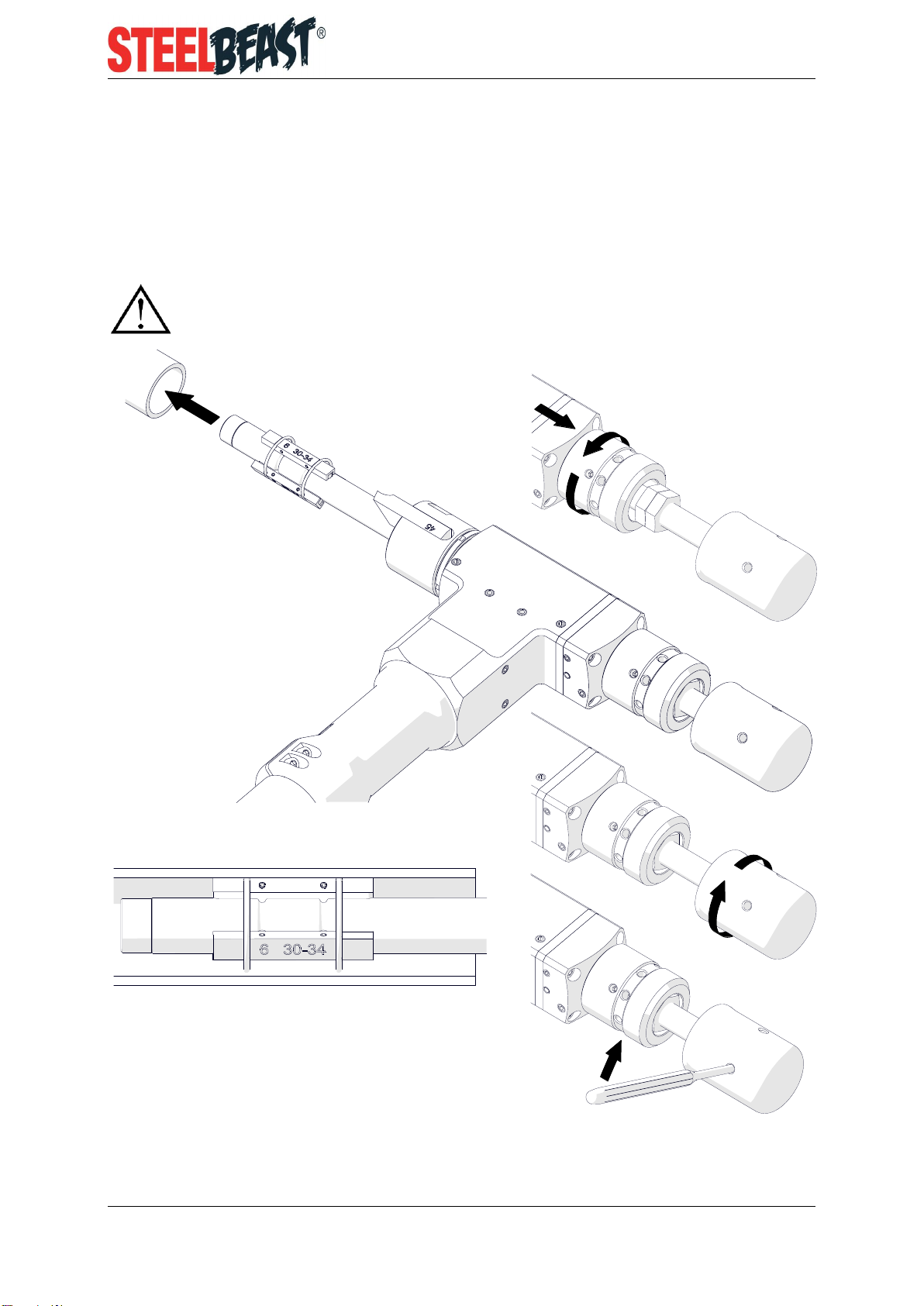
3.3. Installing the motor
When using the air motor, attach the adapter (1, Fig. 5). Attach the correct driver to
the motor (2). Put the motor into the machine (3) so that the driver is in the socket
(4). Then, use the 4 mm hex wrench to tighten the screws (5).
In the electric/battery motor, set the rotation direction switch as shown in Fig. 1.
In the battery motor, set the rotation direction switch and the operation mode switch
as shown in Fig. 1.
Fig. 5.Installing the air, electric, and battery motor
2
3
2
2
3
4
5
1
PB2
This document is protected by copyrights.
Copying, using, or distributing without permission of JEI Group Ltd is prohibited.
14
3.4. Clamping the machine into the pipe
Rotate the feed knob (1, Fig. 6) to retract the machine to the required start point of
the feed (2). Put the machine into the pipe (3) to set the tool bits at least 3 mm (0.12″)
from the pipe end. Next, rotate the clamping knob (4) to expand the jaw blocks and
clamp the machine into the pipe (5).
Use the handle (6) to tighten the clamping knob.
Fig. 6.Clamping the machine into the pipe
2
3
4
5
1
6

PB2
This document is protected by copyrights.
Copying, using, or distributing without permission of JEI Group Ltd is prohibited.
15
3.5. Preparing the air (for machine with air motor)
Connect the machine to a correctly prepared air source of sufficient purity. Make sure
that all inner diameters of the air source (including the supply hose and fittings) are of
at least 10 mm (0.4″). Make sure that the air source has an air preparation unit that
contains a filter, regulator, and lubricator (FRL).
Maintain the FRL unit as required. Keep the water trap drained, filter cleaned,
and the lubricator oil reservoir filled so that there is a drop of oil every 2–5 seconds.
Use oil whose ignition temperature is more than 260°C (500°F). If you are not going
to use the machine for at least 24 hours, increase the supply of oil and let the motor
operate for 2–3 seconds. This will prevent rusting and degrading of the rotor vanes.

PB2
This document is protected by copyrights.
Copying, using, or distributing without permission of JEI Group Ltd is prohibited.
16
3.6. Operating
After you connect the machine to the correct supply, press the ON/OFF lever to start.
In the electric/battery motor, set the gear 1. In the battery motor, set the gear 1
and the maximum torque, and then press and hold the ON/OFF switch. To lock the
switch in the position ON (not available in the battery motor), press the ON switch
lock before you release the ON/OFF switch. To adjust the speed, use the dial or, in
the battery motor, change the force you apply on the ON/OFF switch.
Apply the coolant on the working edge. Then, rotate the feed knob to the right to
bring the tool bits close to the pipe. If needed, put the handle into the knob hole and
rotate the handle to start the feed (1, Fig. 7).
After some rotations, retract the tool bits from the workpiece (2). Then,
use the handle to tighten the knob and remove the clearance (3).
Fig. 7.Using the handle
If the pipe end is not perpendicular to the pipe axis, the tool bit will cut only a
small part of the pipe during initial rotations. Thus, use a low feed rate until the tool
bit is in continues contact with the pipe during at least one rotation. The feed is
1.5 mm (0.06″) per one full turn of the feed knob.
Rotate the feed knob to the right to continue machining. Use such a feed rate so
that the chip is continuous. If the feed rate is too low, only small chips are removed.
If the feed rate is too high, machining is difficult and the chips are rough or torn.
1
3
2

PB2
This document is protected by copyrights.
Copying, using, or distributing without permission of JEI Group Ltd is prohibited.
17
Do not allow the tool bit to burnish the surface. If chatter problems occur, decrease
the feed rate and the speed. Then, make sure that the tool bits are sharp and that
you use the tool bits of correct type for the material. Stainless steel can harden
during work. Thus, cut stainless steel with a high enough feed, 0.08–0.15 mm
(0.003–0.006″) per rotation, to cut under the hardened surface.
If an overload occurs and the rotation stops, promptly turn off the
motor. The motor turned off too late can cause damage to the machine.
To start the work again, rotate the feed knob to the left to retract the tool bits from
the pipe. Then, start the motor and cut the material with a lower feed rate. Do not let
the motor overload. If possible, cut hard materials with a low feed rate and speed.
After the pipe end is machined fully, stop rotating the feed knob and allow several
more turns of the spindle to improve the finish of the surface. Then, use the ON/OFF
lever/switch to turn off the motor, and wait until the rotation stops. Next, rotate the
feed knob to the left to move the tool bits away from the pipe end to at least 3 mm
(0.12″). Then, rotate the clamping knob to the left to release the clamping, and
remove the machine from the pipe.
Use petroleum ether to clean the pipe from excess coolant. Clean the machine
with a cotton cloth and no chemical agents.

PB2
This document is protected by copyrights.
Copying, using, or distributing without permission of JEI Group Ltd is prohibited.
18
3.7. Troubleshooting the electric motor
If the LED is on, the motor power has been decreased. This prevents overheating of
the motor as a result of frequent overload. To decrease the temperature of the motor,
let the motor operate with no load at the maximum speed.
If the LED flashes fast, the automatic restart has been prevented after a power
failure. Then, to start the motor, switch it off and on.
If the LED flashes slow, the carbon brushes are almost worn and the motor
has been shut off. Replace the brushes with new ones specified by the manufacturer
of the motor.
3.8. Troubleshooting the battery motor
If the motor is frequently overloaded for extended periods, it will be shut off. To stop
the beeping signal, release the ON/OFF switch. If you feel that the motor or the
battery is warm, before use wait until its temperature decreases. To decrease the
temperature more quickly, let the motor operate with no load at the maximum speed.
If the LED flashes, the battery is almost discharged. To check the charge level,
press the LED activation button. If the battery is discharged fully, charge the battery
or replace to a fully charged.

PB2
This document is protected by copyrights.
Copying, using, or distributing without permission of JEI Group Ltd is prohibited.
19
4. ACCESSORIES
4.1. Tool bits for carbon steel
NOZ-000071
0–1 short
0° facing tool bit
NOZ-000072
0–2 long
0° facing tool bit
NOZ-000073
30° bevelling tool bit
NOZ-000074
37.5° bevelling tool bit
NOZ-000075
45° bevelling tool bit

PB2
This document is protected by copyrights.
Copying, using, or distributing without permission of JEI Group Ltd is prohibited.
20
4.2. Tool bits for stainless steel
NOZ-000078
0–1 short
0° facing tool bit
(TiAlN coated)
NOZ-000079
0–2 long
0° facing tool bit
(TiAlN coated)
NOZ-000080
30° bevelling tool bit
(TiAlN coated)
NOZ-000081
37.5° bevelling tool bit
(TiAlN coated)
NOZ-000082
45° bevelling tool bit
(TiAlN coated)
Table of contents
Other SteelBeast Power Tools manuals

Popular Power Tools manuals by other brands

Pace
Pace TD-100 Operation and maintenance manual

Robland
Robland Z500 Series manual

Bosch
Bosch GSH 27 VC Professional Original instructions

Weston
Weston 07-0801 instructions

Yard force
Yard force LT V12 Original instructions

Campbell Hausfeld
Campbell Hausfeld DG460300CK S Operating instructions and parts manual

EINHELL
EINHELL TC-JS 18 Li Original operating instructions

jbc
jbc PA quick start guide

strapex
strapex STB 65 operating instructions

molex
molex 63816-0100 Operating and maintenance instructions

Alpha tools
Alpha tools AOF 1100E operating instructions

Chicago Electric
Chicago Electric 66001 Set up and operating instructions


