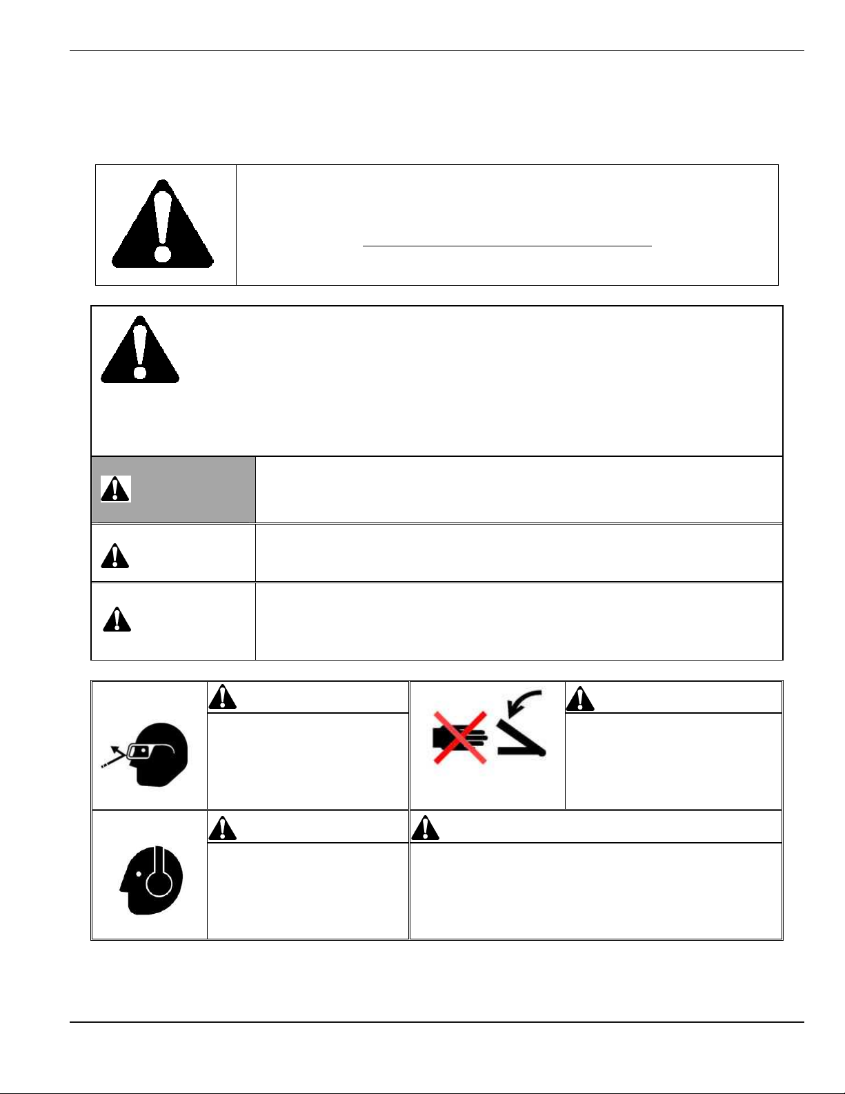
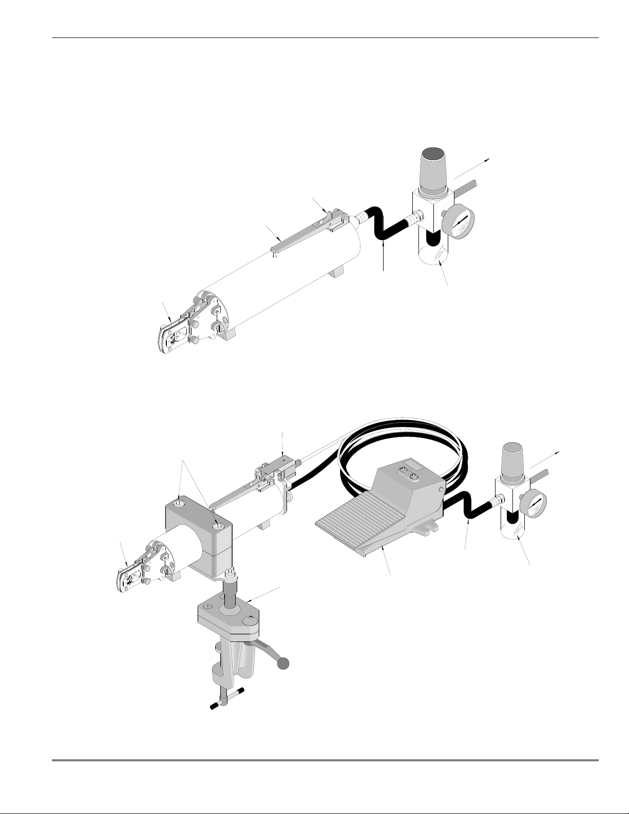
manuals.online logo
Brands
  1. Home
  2. •
  3. Brands
  4. •
  5. molex
  6. •
  7. Power Tools
  8. •
  9. molex 63816-0100 Manual

molex 63816-0100 Manual

This manual suits for next models

1

Other molex Power Tools manuals

molex 90327 Series User manual

molex

molex 90327 Series User manual

molex 63811-7500 User manual

molex

molex 63811-7500 User manual

molex 63819-7300 User manual

molex

molex 63819-7300 User manual

molex TM-3000 User manual

molex

molex TM-3000 User manual

molex RHT 2251 User manual

molex

molex RHT 2251 User manual

molex VHDCI User manual

molex

molex VHDCI User manual

molex 63816-0200 User manual

molex

molex 63816-0200 User manual

molex 69020-0660 User manual

molex

molex 69020-0660 User manual

molex 63811-3300 User manual

molex

molex 63811-3300 User manual

molex 207129 Series User manual

molex

molex 207129 Series User manual

molex 63816-1700 User manual

molex

molex 63816-1700 User manual

molex TM-3000 User manual

molex

molex TM-3000 User manual

molex TM2000 User manual

molex

molex TM2000 User manual

molex 35477 Series User manual

molex

molex 35477 Series User manual

molex 63827-2000 User manual

molex

molex 63827-2000 User manual

molex TM2000 User manual

molex

molex TM2000 User manual

molex TM-3000 User manual

molex

molex TM-3000 User manual

molex 63823-5600 User manual

molex

molex 63823-5600 User manual

molex 69020-1908 User manual

molex

molex 69020-1908 User manual

molex 57131-6000 User manual

molex

molex 57131-6000 User manual

molex Mini Mi2 User manual

molex

molex Mini Mi2 User manual

molex 63816-0270 User manual

molex

molex 63816-0270 User manual

molex 19286-1000 User manual

molex

molex 19286-1000 User manual

molex 63811-0300 User manual

molex

molex 63811-0300 User manual

Popular Power Tools manuals by other brands

ISLAND HOPPER Power Egg HT-309 operating instructions

ISLAND HOPPER

ISLAND HOPPER Power Egg HT-309 operating instructions

Sioux Tools SSR6P25 Instructions-parts list

Sioux Tools

Sioux Tools SSR6P25 Instructions-parts list

Makita HM1317C technical information

Makita

Makita HM1317C technical information

ABB Smart Tool + quick start guide

ABB

ABB Smart Tool + quick start guide

Baumr-AG BMJK-24S user manual

Baumr-AG

Baumr-AG BMJK-24S user manual

Bosch Professional GST 18 V-LI S Original instructions

Bosch

Bosch Professional GST 18 V-LI S Original instructions

Ronix RA-2702 quick start guide

Ronix

Ronix RA-2702 quick start guide

Nordson ProBlue user guide

Nordson

Nordson ProBlue user guide

aoyue int6028 instruction manual

aoyue

aoyue int6028 instruction manual

Hitachi CJ 65VA2 Instruction manual and safety instructions

Hitachi

Hitachi CJ 65VA2 Instruction manual and safety instructions

Makita HM1304 instruction manual

Makita

Makita HM1304 instruction manual

Kurtz Ersa Ersa X-TOOL VARIO operating instructions

Kurtz Ersa

Kurtz Ersa Ersa X-TOOL VARIO operating instructions

SCHUNK KSO 65 Installation and operating instruction

SCHUNK

SCHUNK KSO 65 Installation and operating instruction

Harken LokHead 500 user manual

Harken

Harken LokHead 500 user manual

Senco DuraSpin ExTPro installation instructions

Senco

Senco DuraSpin ExTPro installation instructions

Ferm JSM1020 Original instructions

Ferm

Ferm JSM1020 Original instructions

Milwaukee M12 FUEL 2559-20 Operator's manual

Milwaukee

Milwaukee M12 FUEL 2559-20 Operator's manual

EINHELL BT-CD 12/2 operating instructions

EINHELL

EINHELL BT-CD 12/2 operating instructions

manuals.online logo
manuals.online logoBrands
  • About & Mission
  • Contact us
  • Privacy Policy
  • Terms and Conditions

Copyright 2025 Manuals.Online. All Rights Reserved.

Air Powered Tool
Order No: TM-638160100 Release Date: 02-20-08 UNCONTROLLED COPY Page 1 of 17
Revisio : B Revisio Date: 05-28-10
AIR POWERED TOOL
Operating and Maintenance Instructions
Order No: 63816-0100
Optional Bench Adapter with Foot Switch
Order No: 63816-0 00
 Descriptio
 Operatio
 Mai te a ce
Air Powered Tool
Order No: TM-638160100 Release Date: 02-20-08 UNCONTROLLED COPY Page 2 of 17
Revisio : B Revisio Date: 05-28-10
Table of Contents
1. Safety War i gs a d I formatio
2. Ge eral Descriptio
3. Set-Up a d Adjustme ts
4. Preve tive Mai te a ce
5. Parts List, Assembly Drawi gs a d Troubleshooti g
Air Powered Tool
Order No: TM-638160100 Release Date: 02-20-08 UNCONTROLLED COPY Page 3 of 17
Revisio : B Revisio Date: 05-28-10
Section 1
Safety War i gs a d I formatio
Read a d understand all of the i structio s a d safety i formatio i this
ma ual before operati g or servici g this tool.
Keep this ma ual available whe usi g this tool.
Replaceme t ma uals are available upo request at o charge at
www.molex.com.
SA ETY
ALERT
SYMBOL
This symbol is used to call your atte tio to hazards or u safe practices which could result i a i jury
or property damage. The sig al word, defi ed below, i dicates the severity of the hazard. The message
after the sig al word provides i formatio for preve ti g or avoidi g the hazard.
DANGER
DANGER:
I dicates a immi e tly hazardous situatio which, if ot avoided, will result i
death or serious i jury.
WARNING
WARNING:
I dicates a pote tially hazardous situatio which, if ot avoided, will result i
death or serious i jury.
CAUTION
CAUTION:
I dicates a pote tially hazardous situatio which, if ot avoided, may result i
mi or or moderate i jury. CAUTION may also be used to alert agai st u safe
practices associated with eve ts that could lead to perso al i jury.
WARNING WARNING
Wear eye protectio whe operati g
or servici g this tool.
Failure to wear eye protectio could
result i serious eye i jury from flyi g
debris.
Pi ch poi ts:
Keep ha ds away from the crimpi g
head whe crimpi g.
Failure to observe this war i g could
result I severe i jury or death.
WARNING WARNING
Wear appropriate ear protectio whe
operati g this tool.
Failure to wear ear protectio could
result i loss of heari g over a period
of time.
I spect tool a d dies before use. Replace a y wor or damaged parts.
A damaged or improperly assembled tool ca break a d strike someo e
earby.
Failure to observe this war i g could result i severe i jury or death.
Air Powered Tool
Order No: TM-638160100 Release Date: 02-20-08 UNCONTROLLED COPY Page 4 of 17
Revisio : B Revisio Date: 05-28-10
NEVER INSTALL OR SERVICE THIS MACHINE WHILE CONNECTED TO THE COMPRESSED AIR
SOURCE.
NEVER WEAR LOOSE CLOTHING OR JEWELRY THAT MAY CATCH IN THE MOVING PARTS OF THIS
TOOL.
CAUTION THE MOLEX 63816-0100 AIR POWERED TOOL IS DESIGNED TO BE USED WITH CRIMP TOOL
HEADS AND TOOLING SUPPLIED BY MOLEX. USE OF TOOL HEADS OR TOOLING FROM ANY
OTHER SOURCE MAY RESULT IN DAMAGE OR INJURY. MOLEX WILL NOT BE LIABLE FOR ANY
DAMAGE OR INJURY FROM USE OF NON-MOLEX COMPONENTS IN THIS TOOL.
WORK SA ELY AT ALL TIMES
or Service, Contact Your Local Molex Sales Office
Molex Application Tooling Group
2200 Wellington Court
Lisle, Illinois 60532 USA
Tel: 1-630-969-4550
ax: 1-630-505-0049
Air Powered Tool
Order No: TM-638160100 Release Date: 02-20-08 UNCONTROLLED COPY Page 5 of 17
Revisio : B Revisio Date: 05-28-10
Section 2
General Description
2.1 Descriptio
2.2 Features
2.3 Tech ical Specificatio s
2.4 Delivery Check
2.5 Tools
Air Powered Tool
Order No: TM-638160100 Release Date: 02-20-08 UNCONTROLLED COPY Page 6 of 17
Revisio : B Revisio Date: 05-28-10
igure 2-1
AIR HOSE
TRIGGER
AIR POWERED
CRIMP ADAPTER
SWIVEL LOCK
BENCH MOUNT
CLAMP (Optional)
OOT SWITCH
(Optional)
MAIN UNIT
2 General Description
Principal Mechanical Parts
2.1 Description
The Molex Air Powered Tool is desig ed to crimp a variety of i sulated a d u i sulated termi als a d splices. This
tool has a automatic retractable system which retur s the crimpi g adapter alo g with the crimpi g dies to the
starti g positio whe the maximum force is reached. It is equipped with a special brake that will stop the forward
motio of the crimpi g dies whe the trigger is released. The crimpi g head ca be rotated 360° for better access
i difficult worki g situatio s. This u it requires a power u it a d a modular crimp tool head.
2.2 Features
 Light weight tool for high qua tities of termi atio s.
 Crimps a wide ra ge of products with i tercha geable tool heads a d tool kits, which reduce the overall cost a d
provide productio flexibility.
 Modular crimp heads are easily a d quickly i tercha ged to reduce productio dow time.
 Operated by ha d or foot, statio ary u it available.
 Modular crimp heads ca be rotated to at a y a gle to accommodate the operator.
Air Powered Tool
Order No: TM-638160100 Release Date: 02-20-08 UNCONTROLLED COPY Page 7 of 17
Revisio : B Revisio Date: 05-28-10
2.3 Technical Specifications
Dimensions (with tool head adaptor)
Le gth 342.9mm (13.50”)
Diameter 65.0mm (2.56“)
Weight 1.3kg (2.98lbs)
Production Rate
600 cycles per hour maximum, depe di g o operator skill a d tool kit i stalled.
Operating Parameters
Cycle Time 1.0 seco ds
Air Co sumptio per Cycle .721 L (.025 cubic feet)
Required pressure of filtered air suppy 6 to 6.5 bar (87 to 94 psi) 8 bar maximum (116 psi)
2.4 Delivery Check
Carefully remove the P eumatic Crimpi g Tool from its shippi g co tai er a d determi e that the followi g
items are i cluded i the package.
 63816-0100 P eumatic Crimpi g U it with tooli g adaptor
 TM-638160100 Operatio Ma ual
2. Tools
The followi g tools are recomme ded for setup a d adjustme ts to this tool.
1. Metric sta dard hex wre ch set
2. Adjustable wre ch
3. Wire stripper / cutter
4. Screwdriver
Air Powered Tool
Order No: TM-638160100 Release Date: 02-20-08 UNCONTROLLED COPY Page 8 of 17
Revisio : B Revisio Date: 05-28-10
Section 3
Set-Up and Adjustments
3.1. Set-up
3.2. I stalli g or Cha gi g Modular Crimp Heads
3.3. Operatio
3.4. Termi al Crimpi g
Air Powered Tool
Order No: TM-638160100 Release Date: 02-20-08 UNCONTROLLED COPY Page 9 of 17
Revisio : B Revisio Date: 05-28-10
TRIGGER
SA ETY
AIR HOSE
ILTER REGULATOR
LUBRICATOR
(NOT SUPPLIED)
TO AIR
SUPPLY
TRIGGER
igure 3-1
MODULE CRIMP
HEAD (RE )
ILTER REGULATOR
LUBRICATOR
(NOT SUPPLIED)
OOT SWITCH
(OPTIONAL)
BENCH
ADAPTER
(OPTIONAL)
TO AIR
SUPPLY
SECURE AIR
CRIMPING TOOL
IN POSITION
MODULE CRIMP
HEAD
(Reference)
igure 3-2
CONNECT TUBING ROM
OOT SWITCH
WITH ITTING
(NOT SUPPLIED)
3.1 Set-Up
1. Read the followi g i structio s before attempti g to operate this tool.
2. Co ect a 8mm or 5/16” air hose to the fitti g attached to the rear of the tool a d to air supply 6 to 6.5 bar (87
to 94 psi). Do ot exceed 8 bar (116 psi). May cause injury or damage to the tool. Air supply must be
equipped with a air filter regulator ( ot supplied by Molex). (Available from a y i dustrial supply co.). See
Figure 3-1.
If cha gi g to the Optio al be ch adapter, remove the air hose a d co ect the tubi g from the footswitch. See
Figure 3-2.
Air Powered Tool
Order No: TM-638160100 Release Date: 02-20-08 UNCONTROLLED COPY Page 10 of 17
Revisio : B Revisio Date: 05-28-10
SA ETY
(UNLOCKED)
SA ETY
(LOCKED)
TRIGGER
igure 3-3
3. Next lock the trigger o the actuator by flippi g the safety switch. Push the safety switch all the way dow o the
e d of the trigger to lock. See Figure 3-3.
Note: Always use the safety or disco ect air supply whe cha gi g crimpi g heads.
4. For the proper crimpi g head see the tool part umber o the label of the termi al/co ector co tai er.
5. Strip proper wire to mi imum le gth located o label of termi al/co ector co tai er or o the air powered crimp
tool head specificatio sheet.
3.2 Installing or Changing Modular Crimp Heads
Before starti g a y work o a y electrical applicatio s:
1. Make sure there are o live cables or parts i the immediate area of the user.
2. Make sure the safety is i the locked positio before cha gi g heads.
WARNING
Remove the power source from the crimpi g tool before
i stalli g a d removi g the modular crimp head.
Installing or Changing heads procedure:
1. Remove the locki g pi s (2) from the air powered crimp adapter o the air powered tool.
2. Pull the modular crimp head out of the adapter head.
3. To replace the modular crimp head, select the correct modular crimp head for the applicatio eeded.
4. While holdi g the air powered tool i o e ha d, grasp the modular crimp head with the other ha d a d slide it i to
the air powered crimp adapter u til the holes i the side plates of the crimp head li e up with the holes i the
adapter.
5. Replace the locki g pi s (2) maki g sure that the modular crimp head is secure. The locki g pi s ca be i serted
from either side of the adapter. See Figure 3-4.