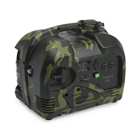
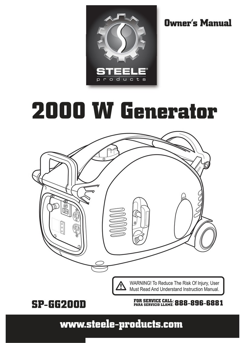
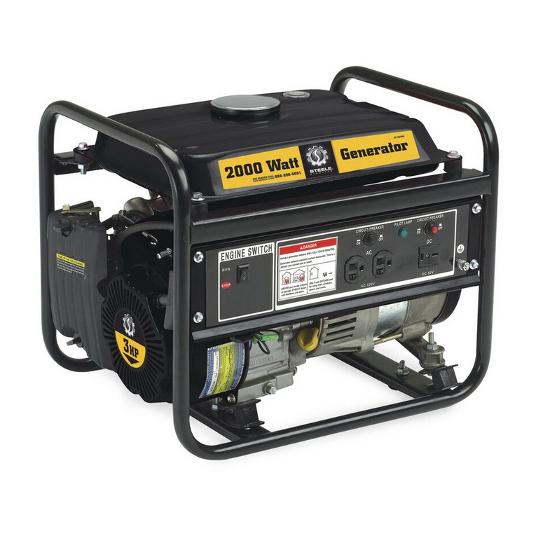
STEELE PRODUCTS SP-GG200TDCM User manual

Owner's Manual
2000W Digital Generator
SPoGG2OOTDCM
[_ ARNING!ToReduceTheRiskOf Injury,User ]
Must Read And Understand Instruction Manual.
FOR SERVICE CALL:o00 OOm EO0t
PARA SERVICID LLAME: u u _-_ u _-_u _ A

•Thank you for purchasing a generator.
•This manual covers operation and maintenance of the generator.
•Reserves the right to make changes at anytime without notice and
without taking any obligation.
This publication can't be reproduced without written
permission.
•Pay special attention to the following words:
•If a problem should arise or if you have any questions,
consult an authorized dealer.
Generator is designed to give safe and
dependable service if operated according to instructions. Read the
Owner's Manual before operating the generator.
Failure to do so could result in personal injury or equipment damage.
CATALOG
SAFETY INSTRUCTIONS
COMPONENT IDENTIFICATION
PRE-OPERATION CHECK
STARTING THE ENGINE
GENERATOR USE
_'_ STOPPING THE ENGINE
MAINTENANCE TIPS & INSTRUCTIONS
TRANSPORTING/STORAGE
TROUBLESHOOTING (FAQS)
SPECIFICATIONS
02
O5
07
10
12
16
18
24
25
28
•Generator is designed to give safe and dependable service if operated
according to instructions.
Read the Owner's Manual before operating the generator.
Failure to do so could result in personal indury or equipment damage.
®
• Exhaust gas is poisonous.Never run the generator
in an enclosed area.
Be sure to provide adequate ventilation.
•Stop the engine before refueling
• Gasoline is extremely flammable and explosive under certain
conditions, Refuel in a ventilated area.
• Keep away from cigarette, smoke and sparks when refueling.
Always refuel in a well-ventilated location.
• Wipe up spilled gasoline.
1 2

• The muffler becomes very hot during operation and remains hot for a
while after stopping the engine.
Do not touch the muffler while it is hot.
Let the engine cool down before moving the generator.
(Pay attention to the warning marks attached to the generator.)
• Always make a pre-operation inspection (page 8) before you start the engine.
• Place the generator at least 1 m (3 ft) away from buildings or other equipment
during operation.
• Operate the genernator on a level surfuce.
If the generator is tilted, fuel spillage may result.
• Know how to stop the generator quickly and understand operation of all the
controls. Never operate the generator without proper
instructions.
• Keep children and pets away from the generator when it is in operation.
• Keep away from rotating parts while the generator is running.
• Do not operate the generator in rain or snow and do not let it get wet.
• Connections from standby power to a building's electrical system must be
made by a qualified electrician and must comply with all applicable laws
and electrical codes
3 4

CONTROL PANEL
•CHOKE LEVER •FUEL CAP LEVER
[
•FUEL CAP
CONTROL PANEL
•OILALERT INDICATOR LIGHT
•OVERLOAD INDICATOR LIGHT
•OUTPUT INDICATOR LIGHT
•DC RECEPTACLE
•DC CIRCULT PROTECTOR
•LEFT SIDE
MAINTENANCE
COVER
•STARTER GRIP
•FUEL COCK
Auto Throttle Switch
•Ground
•AC Receptacle
"SPARKPLUG
MAINTENANCE
COVER
•MUFFLER
6

@Check oil level.
Loosen the cover screw and remove the left side maintenance cover.
Remove the oil filler cap, and wipe the dipstick with a clean rag. Check the oil
level by inserting the dipstick in the filler hole without screwing it in.
Ifthe oil level is below the end of the dipstick, refill with recommended oil
(SAE 10W-30/0.5L)
•OIL FILLER HOLE
"UPPER LEVEL
•OIL FILLER CAP
m_
10W-40
roD•
-30 -20 -10 0 10 20 30 40
Surroundingtemperature ('C)
Select the engine oil according
tothe surrounding temperature.
CAUTION:
Using nondetergent oil or 4-stroke engine oil could shorten the engine's service
life.
Please use high-detergent, premium quality 4-stroke engine oil.
Running the engine with insuffcient oil can cause serious engine damage.
NOTE: The Oil Alert System will automatically stop the engine before the oil level falls
below the safe limit. However, to avoid the inconvenience of an unexpected shut-
down, it is still advisable to inspect the oil level regularly.
@ Check the fuel level.
Unleaded or Iowleaded is preferred to minimize com-bustion chamber deposits.
If the fuel level is low, refuel the fuel tank.
Never use an oil/gasoline misture or dirty 9asoline.
Avoid 9ettin9 dirt, dust or water in the fuel tank.
After refueling, tighen the fuel filler cap securely.
•UPPER LIMIT MARK
•FUEL FILLER CAP
-OPEN
7 8

® Check the air cleaner.
Check the air cleaner element to be sure it is clean and in good condition.
Loosen the cover screw and remove the left side maintenance cover.
Press the latch tab on the top of the air cleaner body, remove the air filter
cover, check the element.
Clean or replace the element if necessary.
.COVER SCREW
•LEFT SIDE
MAINTENANCECOVER
.COVER SCREW •CLEANERCOVER
-- • AIR FILTER
-- •AIR FILTER ELEMENT
Before starting the engine, disconnect any load from the receptacle.
(_Turn the fuel cap lever fully clockwise to the ON position.
NOTE: Turn the fuel cap lever to the OFF position when transporting the generator
-FUELCAPLEVER
@Turn the fuel switch to the ON position.
• FUEL SWITCH
® Move the choke lever to the CLOSED position.
-CHOCK
[CLOSED
9 10

® Pull the starter grip until resistance is felt, then pull the starter grip briskly toward the
arrow as shown below.
CAUTION: Do not allow the starter grip to snap back•
GRIP
® Move the choke lever to the OPEN position as the engine warms up.
NOTE: If the engine doesn't work by starting several times, check the engine oil
level before trouble shooting other areas.
• To prevent electrical shock from faulty appliances, the generator should be
grounded.
Connect with a heavy wire between the generator ground terminal
and on external ground source.
• Connections from standby power to a building's electrical system must be made
by a qualified electrician and must comply with all applicable laws and electrical
codes. Improper connections make electrical current from the generator to
backfeed into the utility lines. Such backfeed may electrocute utility company
workers or others who contact the lines during a power outage, and when utility
power is restored the generator may explode,burn,or cause fires in the building's
electrical system.
( H "-_ ]
CLOSED
•CHOKE LEVER
•GROUNDTERMINAL
(_AC applications
• Start the engine and make sure the output indicator light (green) is on.
Make sure that the appliance to be used is switched off, and plug in the appliance.
11 12

--" OIL ALERT INDICATOR LIGHT
INDICATOR LIGHT
RECEPTACLE
Output and Overload indicators
The output indicator light (green) will remain ON during operating conditions.
If the generator is overloaded (more than 1.OKVA), or if there is short in the
connected appliance, the output indicator light (green) will go OFF, the overload
indicator light (red) will go ON and current to the connected appliance will be
shut off.
Stop the engine if the overload light (red) comes ON and investigate the
overload source, start it after the overload light is OFF.
• Before connecting on appliance to the generator, check that it is ingood order,
and its electrical rating does not exceed the power of the generator.
Then connect the power cord of the appliance, and start the engine.
(_) DC application
The DC receptacle may be used for charging 12 volt automotive-type batteries
only.
• To prevent from creating a spark near the battery, connect charg-
ing cable first to the generator, then to the battery, Disconnect cable first at
the battery.
• Connect the positive battery terminal to the positive charging cord.
Do not reverse the charging cables, or serious damage to the generator
and battery may occur.
NOTE:
•An overloaded DC circuit will trip the DC circuit protector (push button comes
out). The DC circuit protector will trip when it's overloaded• If this happens,
wait a few minutes before pushing in the circuit protector
before resuming operation•
•DC CIRCUIT PROTECTOR
III IIO
ON OFF
.PLUG
•Auto Throttle Switch
When the generator is at charge function
condition and have not any other load,
it can saves your charge time if you start
the AUTO THROTTLE switch•
But the AUTO THROTTLE switch is OFF
in usually situation• AUTO THROTTLE SWITCH
13 14
•The battey gives off explosive gases; keep sparks, flames and cigarettes away.
Provide adequate ventilation when charging.
• The battey contains sulfuric acid (electrolyte). If it gets into your skin or eyes it will
cause severe burns. Wear protective clothing and a face shield.
- If electrolyte touches your skin, flush with water.
- If electrolyte gets into your eyes, flush with water for at least 15 minutes and
and consult a doctor.
•Electrolyteis poisonous.
- Do not swallow!!
• KEEP OUT OF REACH OF CHILDREN
®OIL ALERT SYSTEM
The Oil Alert system is designed to prevent engine damage caused by an insuffi-
cient amount of oil in the crankcase. Before the oil level in the crankcase falls
below a safe limit, the Oil Alert system will automatically shut down the engine.
The Oil Alert indicator light (red) will
come on when you operate the starter, and the engine will not run. If this occurs,
add engine oil.
To stop the engine in an emergency, turn the engine switch to the STOP position.
IN NORMAL CONDITION:
O Switch off the connected equipment and pull out the inserted plug.
.PLUG
@ Turn the fuel switch to the OFF position.
•OIL ALERT INDICATOR LIGHT (RED)
15 16

® Turn the fuel cap lever counterclockwise to the "OFF" posiltion.
CAUTION: Be sure the fuel cap lever and the engine switch are "OFF"
when stopping, transporting and/or storing the generator.
•FUEL CAP LEVER
•OFF
•ON
The purpose of maintenance and adjustment schedule is to keep the generator
in the best operating condition.
Inspect or service as scheduled in the table below.
Shut off the engine before performing any maintenance. If the engine has to be run,
make sure the area is well ventilated. The exhaust contains poisonous carbon mono
-xide gas.
CAUTION:
Use genuine parts or their equivalent parts. The use of replacement parts
which are not of equivalent quality may damage the generator.
Maintenance Schedule
REGULARSERVICEPERIOD(1)
Performofeveryindicatedmonth
or operatinghourinterval,
whicheveroccursfirst. EACH USE FIRSTMONT_
OR10HRS
EVERY3
MONTHS
OR50HRS
Check o
Engine oil Change ©
Check ©
Air cleaner Clean o (2)
Spark plug Clean-adjust
Valvedclearance Check-adjust o (3)
Fueltankandstrainer Clean o (3)
Fuel line Check Every 2 years (Replace if necessary) (3)
EVERY6 EVERY
MONTHS YEAR
OR100HRS OR300HRS
O
NOTE: (1) Run several hours to determine proper maintenance.
(2) Maintenance taken more frequently when used in dusty areas.
(3) These items should be seviced by an authorized dealer, unless the
owner has the proper tools and is mechanically proficient. See the
owner's Manual.
17 18

OCHANGINGOIL
Draintheoilwhiletheengineisstillwarm.
CAUTION: Make sure to turn the engine switch and the fuel cap lever OFF be-
fore draining•
•Loosen the cover screw and remove the left side maintenance cover.
• Remove the oil filler cap.
• Drain dirty oil into a container thoroughly
• Refill with the recommended oil, and check the oil level.
• Reinstall the left side maintenance cover and tighten the cover screw securely.
ENGINE OIL CAPACITY: 0.50L
•OIL FILLER CAP
•OIL FILLER HOLE
@ AIR FILTER CLEANING
A dirty air filter will restrict air flowing into the carburetor. To prevent carburetor
malfunction, service the air filter regularly. Service more frequently when opera-
ting the generator in extremely dusty areas.
--" LEFT SIDE
MAINTENANCE COVER Do not use gasoline or low flash point solvents for cleaning. They
are flammable and explosive under certain condlitions.
.COVER SCREW
•LEFT SIDE MAINTENANCE COVER
19 20

•AIR FILTER ELEMENT
FILTER GAP
®SPARK PLUG SERVICE
RECOMMENDED SPARK PLUG: CR5H88 (NGK) U16FSR - UB (DENSO)
To ensure proper engine operation, the spark plug must be properly gapped
and free of deposits.
•Remove the spark plug maintenance cover.
•ELEMENT
•SPARK PLUG
MAINTENANCE
COVER
CAUTION: Never run the generator withoutthe air cleaner. Rapid engine wear
can occur.
•Loosen the cover screw and remove the left side maintenance cover.
• Press the latch tab on the top of the air cleaner body, and remove the air clean-
er cover.
• Wash the element in a non-flammable or high flash point solvent and dry it
thoroughly.
• Soak the element in clean engine oil and squeeze out the excess oil.
• Reinstall the air cleaner element and the cover.
• Reinstall the left side maintenance cover and tighten the cover screw securely.
•Remove the spark plug cap.
• Clean any dirt around the spark base.
• Use the wrench to remove the spark plug.
•HANDLE
•SPARK PLUG CAP
I
• PLUG WRENCH
21 22

• Visually inspect the spark plug. Discard it if the insulator is cracked
Clean the spark plug with a wire brush if it can be reused.
• Measure the plug gap with a feeler gauge.
The gap should be 0.6-0.7mm,correct as necessary by carefully bending the
side electrode.
• Install the spark plug carefully, by hand, to avoid cross-threading. Make sure to drain the fuel completely. During transporting or during storage.
• After a new spark plug has been seated by hand, it should be tightened 1/2 turn
with a wrench to compress its washer.
If a used plug is being reinstalled, it should only require 1/8 to 1/4 turn after being
seated.
• reinstall the spark plug cap.
• Reinstall the spark plug mainenance cover.
CAUTION:
•The spark plug must be securely tightened. An improperly tightened plug can
become very hot and possibly damage the generator.
•Never use spark plug with an improper heat range.
To prevent fuel spillage when transporting or during temporary storage, the gene-
rator should be secured upright in its normal operating position, with the engine
switch OFF. The fuel cap level turned fully to the "OFF" position.
Avoid direct sunlight when putting the generator on a vehicle.
Ifthe generator is left in an enclosed vehicle for many hours, high temperature in-
side the vehicle could cause possible explosion.
Before storing the unit for an extended period:
Be sure the storage area is free of excessive humidity and dust.
Long-term storage (over 30 days) information:
If you need store this engine for a long term (over 30 days), please follow the
following instructions.
1. Make sure the gas tank is empty.
2. Empty out engine oil.
3. Turn all the the switches OFF.
23 24

When the engine will not start:
1.
Is there fuel in the tank?
NO
Refill the fuel tank.
I2.
Is there enough oil in the engine?
NO
ITo check:
1. Remove the spark plug cap and clean any dirt around the spark plug.
2. Remove the spark plug and install the spark plug in the plug cap.
3. Set the plug side electrode on the cylinder head to ground.
4. Pull the recoil starter, spark should jump across the gap.
Add the recommended oil
3.
Is there a spark from the spark plug?l ]
NO
I
[
Replace the spark plug.
Still No spark
Take the generator to an
authorized dealer.
I
1
Be sure there is no spilled fuel
around the spark plug.
IYES
If the engine still does
not start, take the generator
to an authorized dealer.
I
25 26

Appliance does not operate:
Is the output indicator light ON?
YES Is the overload indicator light ON?
YES
NO
Check the electrical appliance or
equipment for any defects.
NO DEFECTS Take the generator to an
authorized dealer.
DEFECTS
Take the generator to an
authorized dealer.
Replace the electrical
appliance or equipment.
Take the electrical appliance
or equipment to an electrical
shop for repair.
Shut off and restart the engine.
No electricity at the DC receptacle:
Is the DC circuit ?
protector on NO Turn the DC circuit protector on.
YES Take the generator to anauthorized dealer.
Engine
Engine type 4_str0kel 0vet head Valve, single cylinder
I
Displacement _ 86cc
Bore X stroke ¢ 54X 38rim
I
Compression ratio 10:1
- - -Enginespeed . 4000_5000r.p.m
Cooling system. Forced air
I
Ignition system . Full transistor
Oil capacity i 0.50L
Fuel tank capacity _ 3.2L
i
Spark plug A7RTC
I
Noise Level (ISO 8528, !0)59dB (A)
Generator
Rated Frequendy (Hz) • 60
AC Output Rated Output (VA) I 1600
'Max Output (VA) ' 2000
I
DC Output 12 V/8.3 A
Dimensions and Weight
Length X Width X Weight 20.86!xll !x17:63!
Dry weight I 47.4 Ibs (21.5 kg)
Certificate
EPA & CETL . approved
27 28

LimitedWarranty LimitedWarranty(cont'd)
Steele® warrantstotheoriginalpurchaserwhousestheproductinaconsumer
application(personal,residentialorhouseholdusage)thatallproductscoveredunderthis
warrantyarefreefromdefectsinmaterialandworkmanshipforoneyearfromthedateof
purchase.Allproductscoveredbythislimitedwarrantywhichareusedincommercialapplications
(i.e.incomeproducing)arewarrantedtobefreeofdefectsinmaterialandworkmanshipfor
90daysfromthedateoforiginalpurchase.Productscoveredunderthiswarrantyincludeair
compressors,airtools,serviceparts,pressurewashersandgenerators.
Steele@ willrepairorreplace,atSteele@'s soleoption,productsor
componentswhichhavefailedwithinthewarrantyperiod.Servicewillbescheduledaccording
tothenormalworkflowandbusinesshoursattheservicecenterlocation,andtheavailabilityof
replacementparts.AlldecisionsofSteele@ withregardtothislimitedwarrantyshallbe
final
Thiswarrantygivesyouspecificlegalrights,andyoumayalsohaveotherrightswhichvaryfrom
statetostate.
RESPONSIBILITYOFORIGINALPURCHASER(initialUser):
Toprocessawarrantyclaimonthisproduct,DONOTreturnitemtotheretailer.Theproductmust
beevaluatedbyanAuthorizedWarrantyServiceCenter.ForthelocationofthenearestAuthorized
WarrantyServiceCentercontacttheretailerorplaceofpurchase.
Retainoriginalcashregistersalesreceiptasproofofpurchaseforwarrantytowork.
UsereasonablecareintheoperationandmaintenanceoftheproductasdescribedintheOwner's
Manual(s).
DeliverorshiptheproducttotheAuthorizedWarrantyServiceCenter.Freightcosts,ifanymust
bepaidbythepurchaser.
IfthepurchaserdoesnotreceivesatisfactoryresultsformtheAuthorizedWarrantyServiceCenter,
thepurchasershouldcontactSteele@.
THISWARRANTYDOESNOTCOVER:
, Merchandisesoldasreconditioned,usedasrentalequipment,orfloorordisplaymodels.
, Merchandisethathasbecomedamagedorinoperativebecauseofordinarywear,misuse,
cold,heat,rain,excessivehumidity,freezedamage,useofimproperchemicals,negligence,
accident,failuretooperatetheproductinaccordancewiththeinstructionsprovidedinthe
Owner'sManual(s)suppliedwiththeproduct,impropermaintenance,theuseofaccessoriesor
attachmentsnotrecommendedbySteele@, orunauthorizedrepairoralterations.
, Repairandtransportationcostsofmerchandisedeterminenottobedefective.
Costsassociatedwithassembly,requiredoil,adjustmentsorotherinstallationandstart=up
costs.
, Expendablepartsoraccessoriessuppliedwiththeproductwhichareexpectedtobecome
inoperativeorunusableafterareasonableperiodofuse.
MerchandisesoldbySteele@ whichhasbeenmanufacturedbyandidentifiedasthe
productofanothercompany,suchasgasolineengines.Theproductmanufacturer'swarranty,if
any,willapply.
, ANYINCIDENTAL,INDIRECTORCONSEQUENTIALLOSS,DAMAGE,OREXPENSETHAT
MAYRESULTFROMANYDEFECTS,FAILUREORMALFUNCTIONOFTHEPRODUCTIS
NOTCOVEREDBYTHISWARRANTY.Somestatesdonotallowtheexclusion,soitmaynot
applytoyou.
,IMPLIEDWARRANTIES,iNCLUDINGTHOSEOFMERCHANTABILITYORFITNESSFOR
APARTICULARPURPOSE,ARELIMITEDTOONEYEARFROMTHEDATEOFORIGINAL
PURCHASE.Somestatesdonotallowlimitationsonhowlonganimpliedwarrantylasts,sothe
abovelimitationsmaynotapplytoyou.
29 30

2 9\ 28
/60
//
i
27
/
/
/
/
//
62
0 ¸_ -_.
37_
15
/
16
/
/
42.
40
41.
\\ _/2
\
4\
21 22
\-.\ 1 \ \\
43
13
®
i
49
EngineExplode
9
/
50
55
61 54
'\ \
63
32
58
/
.... -_56
PartsListing
APA Part No. Description Part No.
APG3102TECM-01
APG3102TECM-02
APG3102TECM-03
APG3102TECM-04
APG3102TECM-05
APG3102TECM-06
APG3102TECM-07
APG3102TECM-08
APG3102TECM-09
APG3102TECM-10
APG3102TECM-11
APG3102TECM-12
APG3102TECM-13
APG3102TECM-14
APG3102TECM-15
APG3102TECM-16
APG3102TECM-17
APG3102TECM-18
APG3102TECM-19
APG3102TECM-20
APG3102TECM-21
APG3102TECM-22
APG3102TECM-23
APG3102TECM-24
APG3102TECM-25
APG3102TECM-26
APG3102TECM-27
APG3102TECM-28
APG3102TECM-29
APG3102TECM-30
APG3102TECM-31
APG3102TECM-32
Cylinder Head Comp. ¢58
Hexagon Flange Bolts M6X12
Head Cover Comp.
Head Cover Gasket
Valve Spring Retainers
Valve Springs
Seal Washers
Valve Pipes
Adjustable Nuts
Valve Arm Shaft
Adjustable Blots
Valve Push Rods
Arm Shaft Pin
Spark Plug(E7RTC)
Ball Bearing(6303) ¢ 17X¢47X14
Crankshaft Comp.
Piston
Combined Oil Ring
Taper Ring
Chromic Ring
Piston Pin
Piston Pin Clips
Valve Patch
Valve Patch Retainer
Screw M3X6
Fixing Pins 6X25
Crank Case Cover
Trigger Winding Subassembly
Hexagon Flange Bolt M5X10
Oil Seal
Hexagon Flange Bolt M6X45
Hexagon Flange Bolts M6X20
3040101010110
0502060121
3040101001000
3040100000600
3040108001400
3040108001200
3040108000500
3040108000100
3040108001100
3040108000300
3040108001000
3040108000200
3040108000400
3040100000400
0510630300
3040107010000
3040105000400
3040105030410
0
0
3040105030510
3040105030610
3030001010600
3030001010700
060403006
3040101000200
3040102000200
31100003
050205010
30100001
050206045
0502060201
PartsListing
APA Part No. Description Part No.
APG3102TECM-33
APG3102TECM-34
APG3102TECM-35
APG3102TECM-36
APG3102TECM-37
APG3102TECM-38
APG3102TECM-39
APG3102TECM-40
APG3102TECM-41
APG3102TECM-42
APG3102TECM-43
APG3102TECM-44
APG3102TECM-45
APG3102TECM-46
APG3102TECM-47
APG3102TECM-48
APG3102TECM-49
APG3102TECM-50
APG3102TECM-51
APG3102TECM-52
APG3102TECM-53
APG3102TECM-54
APG3102TECM-55
APG3102TECM-56
APG3102TECM-57
APG3102TECM-58
APG3102TECM-59
APG3102TECM-60
APG3102TECM-61
APG3102TECM-62
APG3102TECM-63
Knob Collet
Magnetic Reed Switch Assembly
Oil Sealed Ring
Oil Sensor Support
Connecting Rod
Connecting Cover
Oil Scoop
Connecting Rod Bolts
Hexagon Flange Bolts M6X25
Exhaust Pipe
Exhaust Pipe Gasket
EX. Valve Retainer
EX. Valve
IN. Valve
IN. Valve Retainer
Valve Lifters
Dowel Pins(6Xl 8)
E-Clamp 4
Governor Gear
Lubricative Gear Shaft
Washer
Gear Case Cover
IN. Camshaft Push Rod
Camshaft Gaskets
EX. Camshaft Gear Subassembly
IN. Camshaft Gear
Valve Pipe Shield Rings
Spindle Tensiondisc
Oil Bearings
Oil Sensor Shield
EX. Camshaft Push Rod
30159005
3030001180200
02700050
3030001180100
304010501000011
3040105000100
3040105000200
30117004
0502060251
3040100001600
3040100001700
3040108000900
3040108000700
3040108000600
3040108000800
40300015
3040101000100
070304001
3040103000200
3040103000300
3040103000400
3040103000100
3040106000100
3040106000200
3040106020000
3040106010100
3040108001300
3040100002000
3040106000300
3040100002100
3040106000100B
31 32

91
/
/
/
9O
89
/
68\
[
11 ......
66
65 ........ 11
51
2 ._
1 i _
.18 ..19
38
• 4O
/
/
/i
/
52 53 /
54
55
99
42
14
/
/
15
..21
104
/
58
/
103
ProductExplode
9
13
/
15
16 5O
/
PartsListing
APA Part No.
APG3102TECM-01
APG3102TECM-02
APG3102TECM-03
APG3102TECM-04
APG3102TECM-05
APG3102TECM-06
APG3102TECM-07
APG3102TECM-08
APG3102TECM-09
APG3102TECM-10
APG3102TECM-11
APG3102TECM-12
APG3102TECM-13
APG3102TECM-14
APG3102TECM-15
APG3102TECM-16
APG3102TECM-17
APG3102TECM-18
APG3102TECM-19
APG3102TECM-20
APG3102TECM-21
APG3102TECM-22
APG3102TECM-23
APG3102TECM-24
APG3102TECM-25
APG3102TECM-26
APG3102TECM-27
APG3102TECM-28
APG3102TECM-29
APG3102TECM-30
APG3102TECM-31
Description Part No.
Engine Assy. 3040100000000
Tension Increasing Fuel Tank
Cap Subassembly
Fueling Port Rubber Ring
Fuel Filter Cup
Fuel Tank Assembly
Shock Absorption Blocks
Spark Plug Cover Board
Enclosure (R)
Lock Slices
Shock Absorption Foots for Chassis
Cross Recessed Pan Head
Tapping Screws ST6.3X19(F type)
Safeguard Tubes(10X1.5)
Hexagon flange bolts(M6X12)
Engine Enclosure (R)
Gaskets
Damping Washers
Sealing Cover
Woodruff Key (3X5X13)
Spindle Subassembly
Hexangon Flange Bolts(M5X30)
Flywheel Rotor Subassemmbly
Hexagon Flange Nut(M10X1.25-8)
Fan Blade
Starting Paw Seat
Hexagon Flange Bolts(M6X16)
Starter Pulley
Hexagon Flange Bolt(M8X14)
Air Director and Air Filter Assy.
High Pressure Rubber Cap
Ignition Coil with Metallic Cap
Cross Recessed Pan Head
Tapping Screws ST4.8X25(F type)
3030101140000
3040000000600
30114002
3040113000100
3030000001700
3040000000400
3040000000200
3030000000800
3030000001900
060506019F
3030001030800
050206012
3040104000200
3030001030700
3030001030600
3040102000200
3030001070800
3040201000000
050205030
3040202000000
0404100011
3040100000700
3040100000800
0502060141
3040100001200
050208014
3040110020000
3040100001300
3040115000000
060504025F
PartsListing
APA Part No. Description Part No.
APG3102TECM-32
APG3102TECM-33
APG3102TECM-34
APG3102TECM-35
APG3102TECM-36
APG3102TECM-37
APG3102TECM-38
APG3102TECM-39
APG3102TECM-40
APG3102TECM-41
APG3102TECM-42
APG3102TECM-43
APG3102TECM-44
APG3102TECM-45
APG3102TECM-46
APG3102TECM-47
APG3102TECM-48
APG3102TECM-49
APG3102TECM-50
APG3102TECM-51
APG3102TECM-52
APG3102TECM-53
APG3102TECM-54
APG3102TECM-55
APG3102TECM-56
APG3102TECM-57
APG3102TECM-58
APG3102TECM-59
APG3102TECM-60
APG3102TECM-61
APG3102TECM-62
APG3102TECM-63
APG3102TECM-64
Hooked Damping Pillar
Hook
Sponge
Air Filter Cover
Tapping Screws ST4.8X32(F type)
Carburettor Seal Gasket B(outlet)
Packing Block
Carburettor Seal Gasket A(outlet)
Carburettor Assy.
Carburettor Seal Gasket(inlet)
Hexagon Flange Nuts M5
Oil Filter Box Gaskets
Oil Filter Box Subassembly
Clip Springs
Connector
Starting Grip
Recoil Starter Rope (1.4m)
Shutter Plastic Board
Recoil Starter Case Comp.
Inverter Subassembly
Panel Frame
Igniting Assy (with pilot lamp)
Bridge Rectifier 1010A
Europeen Type IC Board
DC Receptacle(with circuit breaker)
Switch
European Type Socket
Screws M5X25
Washers 4
Bolts M6X120
Seal Cap for Cover Board (L)
Screw M6X14
Cover Board of the Enclosure(L)
3040114010000
3040114000100
3040110000100
3040110000200
060504032F
3040100000200
3040100000300
3040100000100
3040109000000
38142153000571
040405001
3040110000300
3040110010000
3030001100900
3030001100800
26301184000091
3030001121000
26301184000111
3040112000000
3040203000000
3040000000500
3030002041900
06731016
3040204010100
01657001
09510031
09510015
060405025
030104001
3030000000200
24304000000041
3030000000500
3040000000300
33 34

PartsListing
APA Part No. Description Part No.
APG3102TECM-65
APG3102TECM-66
APG3102TECM-67
APG3102TECM-68
APG3102TECM-69
APG3102TECM-70
APG3102TECM-71
APG3102TECM-72
APG3102TECM-73
APG3102TECM-74
APG3102TECM-75
APG3102TECM-76
APG3102TECM-77
APG3102TECM-78
APG3102TECM-79
APG3102TECM-80
APG3102TECM-81
APG3102TECM-82
APG3102TECM-83
APG3102TECM-84
APG3102TECM-85
APG3102TECM-86
APG3102TECM-87
APG3102TECM-88
APG3102TECM-89
APG3102TECM-90
APG3102TECM-91
APG3102TECM-92
APG3102TECM-93
APG3102TECM-94
APG3102TECM-95
Screw M4X12
Fuel Switch Turn Knob
Screws M6X14
Enclosure (L)
Power Switch
Switch Cover
Tapping Screws ST4.2X9.5(F type)
Fuel Switch
Oil Outlet Pipe
Protective Spring
Fue Pump Oil Injecting Pipe A
Seal Ring
Oil Cover with Meter
Double Head Screws
Fuel Filter
Fuel Pump Outlet Pipe
Fuel Pump Air Pipe
Fuel Pump Oil Injecting Pipe B
Fuel Pump Assy.
Tapping Screw ST4.8X19
Engine Enclosure (L)
Tapping Screws ST4.2X16(F type)
Respirator Connecting Sleeve
Gasket
Muffler Assy.
Hexagon Flange Bolts(M6X55)
Rubber Frame
Rear Enclosure
Screws M5X20
Spring
Rubber O-Ring(20X1.8)
060404012
3030001150100
060404014
3040000000100
3030000001800
3030000002100
060504095F
38301184000931
3040113000200
3040100001400
3040100000900
24301169000411
26301169000401
3040101000300
3040100001800
3040100001100
3040100001000
3040100001900
3030001200000
060504819S
3040104000100
060504016F
3030001001100
3040100001500
3040111000000
050206055
3040000000800
3040000000700
060405020
3040000000900
020120001
PartsListing
APA Part No. Description Part No.
APG3102TECM-96 Washers 3030001112600
APG3102TECM-97 Clip Springs 3030001000900
APG3102TECM-98 Gaskets 5 030105001
APG3102TECM-99 Screw M5X12 060405012
APG3102TECM-100 I-Type Hexagonal Nut (M4) 0401040012
APG3102TECM-101 Spring Washer(Standard Model) 4 0305040012
APG3102TECM-102 Gasket 4 030104001
APG3102TECM-103 Screw M4X14 06020403010
APG3102TECM-104 Gasket 10 030110001
APG3102TECM-105 Turret Bolt with Washer M5X12 080405012
Distributed by:
ALL-POWER AMERICA
730 SEpperson Dr.
City Of Industry,CA91748
www.allpoweramerica.com
35 36

DANGER
Carbon Monoxide
Using a generator indoors WiLL KiLL YOU iN MINUTES.
Carbon Monoxide
Generator exhaust contains high levels of carbon monoxide (CO), a poisonous
gas you cannot see or smell• If you can smell the generator exhaust, you are
breathing CO. But even Ifyou cannot smell the exhaust, you could be breathing
CO.
•NEVER use a generator inside homes, garages, crawlspaces, or other partly
enclosed areas• Deadly levels of carbon monoxide can build up in these areas•
Using a fan or opening windows and doors does NOT supply enough fresh air.
•ONLY use a generator outdoors and far away from open windows, doors, and
vents• These openings can pull in generator exhaust•
Even when you use a generator correctly, CO may leak into the home. ALWAYS
use a battery-powered or battery-backup CO alarm in the home.
If you start to feel sick, dizzy, or weak after the generator has been running,
move to fresh air RIGHT AWAY. See a doctor. You could have carbon
monoxide poisoning.
Table of contents
Other STEELE PRODUCTS Portable Generator manuals

STEELE PRODUCTS
STEELE PRODUCTS SP-GG300 User manual

STEELE PRODUCTS
STEELE PRODUCTS SP-GG1000E User manual

STEELE PRODUCTS
STEELE PRODUCTS SP-GG200 User manual

STEELE PRODUCTS
STEELE PRODUCTS SP-GL350 User manual

STEELE PRODUCTS
STEELE PRODUCTS SP-GG350 User manual

STEELE PRODUCTS
STEELE PRODUCTS SPGG900E User manual

STEELE PRODUCTS
STEELE PRODUCTS SP-GG600 User manual

STEELE PRODUCTS
STEELE PRODUCTS SP-GG100 User manual

STEELE PRODUCTS
STEELE PRODUCTS SP-GG200D User manual

STEELE PRODUCTS
STEELE PRODUCTS SP-GG120 User manual