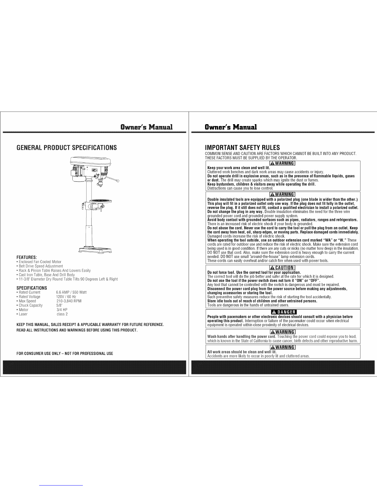
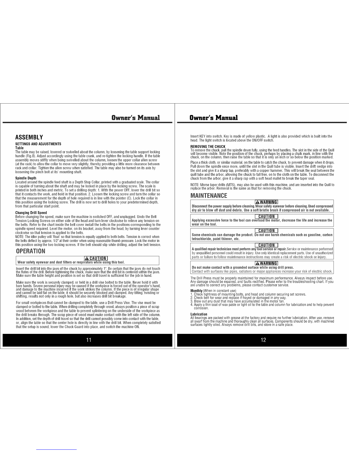
STEELE PRODUCTS SP-PB214 User manual

Owner's Msnuel
14" Drill Press
SP-PB214
[_ WARNING!ToReduceTheRiskOfInjury,User]
L_ M_ InstructionManual.
FORSERVICECALL:@@O @O_ _@@1
PARA SERVICIO LLAME: uuu-u_umuuu&

Owner's Manual
RECOGNIZESAFETYSYMBOLS,WORDSANDLABELS
WhatYouNeedtoKnowAboutSafetyInstructions
Warningand ImportantSafetyInstructionsappearingin this manualarenot meantto coverall possible
conditions andsituationsthat may occur.Commonsense,caution andcaremust beexercisedwhen
assemblingor usingthis product.
Alwayscontactyour dealer,distributor, serviceagent or manufacturerabout problemsor conditions
you do not understand.
FAWARr,JiNG] Thisisasafetyalertsymbol,It isusedto alertyouto potentialpersonalinjun/hazards,
Obeyall safetymessagesthat follow this symbolto avoid possible injury or death,
L I_:AIITION I Thisisasafetyalertsymbol,Itis usedto alertyouto potentialpersonalinjun/hazards,
Obeyall safetymessagesthat follow this symbolto avoid possible injury or death,

Owner's Manual
GENERALPRODUCTSPECiFiCATiONS
FEATURES:
oEnclosedFanCooledMotor
oBeltDrive SpeedAdiustment
o Rack& Pinion TableRaisesAnd LowersEasily
o Casthon Table, BaseAnd Drill Body
o!!o3/8" Diameter Dry RoundTableTilts 90 DegreesLeft& Right
SPECiFiCATiONS
o RatedCurrent 6.6 AMP/550 Watt
oRatedVoltage !20V /BOHz
o Max Speed 210-3,840 RPM
oChuckCapacity 5/8"
oMotor 3/4 HP
oLaser class2
KEEPTHIS MANUAL, SALESRECEIPT& APPLICABLEWARRANTYFORFUTUREREFERENCE.
READALLINSTRUCTIONSANDWARNINGSBEFOREUSINGTHIS PRODUCT.
FORCONSUMERUSEONLY- NOTFORPROFESSIONALUSE
Owner's Manual
IMPORTANTSAFETYRULES
COMMONSENSEANDCAUTIONAREFACTORSWHICHCANNOTBEBUILTINTOANYPRODUCT.
THESEFACTORSMUSTBESUPPLIEDBYTHEOPERATOR.
[,_WARNINGI
Keepyourwork areacleanand well lit.
Clutteredwork benchesand darkwork areasmay causeaccidentsor injury.
Donot operate drill in explosiveareas, suchas in the presence of flammable liquids,gases
or dust. Thedrill maycreatesparks which may ignite the dust or fumes.
Keepbystanders,children& visitorsaway while operating the drill.
Distractionscan causeyou to losecontrol.
[AWARNING]
Doubleinsulatedtoolsare equippedwitha polarizedplug(one bladeiswiderthanthe other.)
This plugwill fit ina polarizedoutletonlyoneway. Ifthe plugdoesnot fitfully in theoutlet,
reversethe plug.If it stilldoesnotfit, contacta qualifiedelectriciantoinstalla polarizedoutlet.
Donot changethe plug in anyway. Double insulation eliminatesthe needfor the three wire
grounded power cordand grounded powersupply system.
Avoidbodycontactwith groundedsurfacessuchas pipes, radiators,rangesandrefrigerators.
Thereis an increasedrisk of electricshock if your body is grounded.
Donotabusethe cord.Never usethe cordtocarrythetoolor pull the plug from an outlet. Keep
thecordawayfrom heat, oil, sharpedges,or movingparts. Replacedamagedcordsimmediately.
Damagedcords increasethe risk of electricshock.
Whenoperating thetool outside, use an outdoor extensioncordmarked"WA" or "W." These
cords are ratedfor outdoor useand reducethe risk of electricshock. Makesurethe extensioncord
beingused isin good condition. Ifthere areanycuts or nicks (no matterhow deep)inthe insulation,
DONOTusethat cord. Also, makesure the extensioncord is heavyenoughto carrythe current
needed.DONOTusesmall "around-the-house"lamp extensioncords.
Thesecords caneasily overheatand/or catchfire when usedwith powertools.
r,a,CAUTIONI
Donot forcetool. Usethe correcttool foryourapplication.
Thecorrect tool will do the job better and saferatthe ratefor which it is designed.
Donot usethe toolif thepower switchdoesnotturnit "ON" or "OFF".
Anytool that cannotbe controlledwith the switch is dangerousand must be repaired.
Disconnectthepower cordplug fromthe power sourcebeforemakinganyadjustments,
changingaccessoriesorstoringthetool.
Such preventivesafety measuresreducethe risk of starting the tool accidentally.
Storeidle toolsout of reachof childrenand other untrainedpersons.
Tools are dangerousin the handsof untrained users.
Peoplewith pacemakers or other electronicdevicesshouldconsultwith a physician before
operatingthis product.Interruption or failure of the pacemakercould occurwhen electrical
equipmentis operatedwithin closeproximity of electricaldevices.
Wash handsafter handling the pewer cord. Touching the power cordcould exposeyouto lead,
which is known inthe StateofCaliforniato causecancer,birth defectsandother reproductiveharm.
IAWARNING]
All werk areas shenid he cleanandwell lit.
Accidentsaremore likelyto occur in poorly fit and clutteredareas.

Owner's Manual
KeepchHdreo,aod other distractioos at adistaoce while operating powertools.
Keepthe powercord ingood condition, and repiace damagedcords immediateiy. Donot use
thecord to pullthe plugfrom the outlet, Keepthe cordawayfrom materialsandsurfacesthat could
damagecords,Therisk of electric shock increaseswhen the power cord isdamaged,
IAWARmNGI I
A_waysusethe appropriate exteosioo cord, making sore it is rated for rise with drills.Always beI
sure the extension cordsarein good condition, free of cuts or nicks in the insulation, If usingthe
dr nanouts de areawth an extenson cord, makesure the cord s ratedfor outdoor use, J
IAWARP,ltrdGI ]
Uo netmake contactwith a gronndedsnrface while using this powertool.
Contactwith surfaceslike pipes, radiatorsor major appliancesincreasesyour riskof electric shock,
[AWARmNGI
Use commonsense while operating this drill.
Do not usethis drill if you are:
Feelingtired or areunderthe influenceof alcohol or drugs,
Wearingloose clothing or jewelry, Keeplong hair pulled backand awayfrom movingparts,
Overreachingor haveimproperfooting, Handlingthe tool inthis way could causeserious injury,
Whenusing this drill always:
. Wearthe proper safety equipment,such as safety goggles,dust masks, non=skidshoes,etc,
. Besure all adjusting keys or wrenches havebeenremovedbeforestarting the drill,
CAUTION
Follow these steps to maintain safe goodworking ceoditieo of power
too_s.lmproper carecan resultin electric shockor seriousinjury,
.Secureandsupportthe workpieceusingclamps,Donot riseyonr handsto holdthe piece inplace.
.Usethe correcttool for the job. Usingthe correcttool is saferand faster.
*lViakesorethe powerswitch isin goodworking order. Ifthe powerswitch no longerturns the
tool "ON"or "OFF",discontinue use,andhavethe tool replacedor repaired,
*Removethe powercord from the powersonrce before storage, changing accessories, or
moving the tool.
*t(eep cot of reach of children, orany untrainedperson,Storetools ina safeand dry place,
.Keeptools clean, andcutting toois sharp. Maintainingtools with propercarewill increasethe
life ofthe powertool, andreducethe risk of injury,
*Checkto be sure aHmoving padsare free from binding and are properlyaligned.
.Useonlyaccessoriesthatare recommendedbythe manufacturerfor yourtool model,
[AWARNI_I
Safety glasses and ear protectionmost heworn doting operation.
ALWAYSWEAREYEPROTECTION.
A drill presscanthrow foreign objects into your eyeswhich could cause
permanenteyedamage.
ALWAYSwearsafety goggles (not glasses).Ordinaryeyeglasses
haveonly impact-resistant lenses...theyARENOTsafety goggles.
Owner's Manual
SERVICE
Toolservice most be performed only by qnalified repair personnel.
Serviceor maintenanceby unqualifiedpersonnelcould result in a risk of injury.
Whenservicingatool, useonlyidentical replacementparts andfollowinstructions in themanual.
Use of unauthorizedpartsor failure to follow maintenanceInstructions may createa risk of shock or
injury.
SAVETHESEINSTRUCTIONSFORFUTUREREFERENCE.
This manualcontains important information regardingsafety, operation,maintenanceand storageof
this product. Beforeuse, readcarefullyand understandall warnings, cautions, instructions and labels.
Failureto do so could result in serious personalinjury, property damageor evendeath.
iIVIPORTANTSAFETYiNSTRUCTiONS i i G
Beforerising this tool, yon needto be ith its operation. If you areunsureabout
the operationof the tool, or haveany questions about its proper use, callthe CustomerService
Departmentat 888-896-6881, Followthese instructions for safe handlingof the tool:
*Always secure aod snppod the workpiece rising clamps.go notriseyonr hands to hold the
piece in place.
*Besore yonrwork area is cleao and secnre before tnrning the power switch intothe "ON"
position. Besure the areais freefrom allforeign material,nails, staples,or any other material,
, Tornthe drill "OFF" and nnplng from the powersontce beforemaking any changes or
adjnstments to the drill.
*go notrise solvents containing carbon tetrachioride, ammonia or acetone to clean the drill.
Neverusegasoline, paintthinner, or other caustic chemicalsthat candamagethe plastic parts of
thetool,
,Always use the appropriate safety gear when operating this drill.Including but not limited, to
goggles, dust mask or respirator, Alwayswork ina weIFventilatedareato reduceyour exposure
to harmful chemicalsand dust particles,
*t(eep haodsaway from the totting area.
,,Do notreach nnder the work piece.
SPECIFICSAFETYRULESAND/ORSYMBOLS
SYI_BOLS
Thefollowing symbols may beused onyour tool, Befamiliar with andlearnthe symbols to operate
the tool safely,
Symbol
V
A
Hz
W
Kg
®
min
S
¢
%
.,./rain
1,2,3.,.
Name
Volts
Amperes
Hertz
Watt
Kilograms
Alternating Current
Direct Current
Alternating or Direct Current
Earthing Terminal
ClassII Construction
Minutes
Seconds
Diameter
No Load Speed
Revohtions per Minute
Ring Selector Settings
Description
Voltage (Potential)
Current
Frequency (Cycles per Second)
Power
Weight
Type of Current
Type of Current
Type of Current
Grounding Terminal
Denotes Double Insulation
Time
Time
Size of Drill Bits, Grinding Wheels, etc,
No-load Rotational Speed
Revohtions,Surface Speed,Strokes, etc. per Minute
Speed,Torque or Position Settings

8_.er's Ma.ual
PACKAGECONTENTS
*16 SpeedDrH[HeadAssemNy
° TaNeAssemNy
* Base
° ConumnAssemNy
° ChuckGuardAssemNy
* Assortednooseparts
COMPONENTS
1
2
3
4
5
6
7
8
9
10
11
Quill FeedSpring Adjustment
Column
FeedHandle
PowerSwitch
LaserLight Switch
Rack
Base
Table
ColumnSupport
Arm LockingHandle
TableLock
ASSORTEDLOOSEPARTS
Allen key 4mm (1)
Allen key 3mm (1)
Wedge key
(1)
V-Belt (2)
r
Pulley cover knob (1)
Chuck key (1)
Chuck (1)
'\/Crank (1)
IIIIIIIIIIIII ZZI/
Hex head screw (4)
Arm locking
handle (1) _'/
handle/ /
(1) _.j/
Owner's Manual
PARTSDESCRIPTION
Laser gui
switch
//
Belt tension
locking knob
Locking
haedle............
scaie
Chuck key .......
Nut
handie
ligth switch
Ddli switch Speed _abe_ Pulley cover
Chuck
Depth
screw
Depth
Depth
Column
tension
kr_ob
Be_t tensfon
handie
n9 screw"
Column col_a_
".Feed
handle
Co,urns

Owner's Manual
ASSEMBLY I
Donotstaredirectlyat the laserbeam. Neveraimthe beamat any personor object other thanthe
work piece.Do not deliberatelyaimthe beamat personnel.Staring atthe beam maycauseflash
b ndness.
NOTE 1
Unpackproductfrom packageandreview contents. Keepannpackaginguntil product hasbeen
reviewed.
Donot operatethe machineuntil it is completelyassembled.
Makesurethe properelectricalregulationsare followed, and that the machineis properly grounded.
Beforeswitching the machineON,ALWAYS:a. Makesure all chuckkeys, spannersandwrenchesare
removedfrom the machine, b.Examinethe setupcarefully, making certainthat the workpiece is
perfectlysecure,c. Makesureyour clothing is properlyadjusted.
Makeall adjustmentswith the powerOFF.
Always usethe correct drilling speedsfor the drill size, andthe type of material beingdrilled. NEVER
leavethe drill unattendedwhile it is running.Turn the machineOFFand do not leaveuntil it has come
to a completestop. Whenyou havefinishedwith the machine,always removeand store the drill bits.
CAUTION:This Drill Pressis designedfor usewith Drill Bits and Mortising attachments ONLY.
The use ofothercuttingtools oraccessoriescouldbe hazardous.ALWAYSuseclamps,ora drill
viseboltedto the table, toholdthework. ItshouldNEVERbe heldin barehands.
Usingthe Laser
The laserlight/laser radiationused inthis lasercentering devicesystemis Class2with maximum
1roWand 40Onto- 70Ontowavelengths.Theselasers do not normally presentan optical hazard,
although staring atthe beam maycauseflash blindness.
Changingthe Batteries
Unclipthe batterycoverto gainaccessto the batteries.ReplacebothAAbatteries,takingcareto insert
the new batterieswith the correct polarity.
Useonly 2AAbatteries.DONOTmixold and newbatteries. DONOTmixalkaline,standard (carbon
-zinc) or rechargeable(nickel-cadmium) batteries.
Replacethe laserlight battery coverand makecertainthat the light is not directedtowards the eyeof
a person. Alwaysmake surethat the laserbeam isaimedat a sturdy work piecewithout reflective
surfaces,i.e. wood or rough surfacesare acceptable.Bright, shiny, reflectivesheet steelor the like is
not suitablefor laser use,asthe reflectivesurface could directthe beambackatthe operator. Only
turn the laser beamonafter the work pieceis in place. CAUTION:Removethe laser light batteries
when tool isto bestored without usefor a few days.
Resetting the Laser Beam
Loosenthe setscrew on eachofthe lasertubes andadjust the tubes until the two beamsintersect at
the point wherethe drill bittouchesthe work piece.Retightenthe set screws more. If left in position,
the batteriesmight leakand damagethe laserlight assembly. Damagecausedby batteryleakageis
not coveredunder warranty.
Owner's Manual
ColumnAssemblyto Base
NOTE:Ideally,the baseshould befirmly boltedto the floor, prior to assemblyof other components.
The mounting surface must beflat, leveland capableof supporting the drill weight.
With the baseon aflat levelsurface,bolt onthe Columnusingthe 4M10 Hexheadscrews provided
and tighten. Carefullylocatethetable in its support andtighten up with thetable locking handle.Check
to makesurethe columnsecuring set screws,at the column support, aretight. Fitthe crankto the
shaftonthe crank assembly.
HeadtoColumn
NOTE:tt may benecessaryto unscrewthe HeadLockSet Screwsslightly to makesurethey do not
protrude internallyas this would preventthe headfrom sliding fully into position. 1. Raisethe head
and locateit ontop of the column. 2. Alignthe headwith the baseand firmly securewith the set
screws usingthe wrench. Locatethe threefeed handlesand screw them into the hub of the spindle
feedshaft.
ChuckGuardAssembly
NOTE:This operationshould becarriedout beforethe chuckis installed.Slidethe ChuckGuardover
the Quillshaft, turn it so thatthe pinchbolt facesthe front, thentighten upthe pinch boltto temporarily
secureit inthis position. IMPORTANTMakesurethe QuillShaft Spindle isat the top of its travel.
PulleyCoverKnob
Locatethe knob, with pan headscrewand attachto the cover,screwing ontightly.
Installingthe Chuck
1. Slidethe table upthe column and secureit to within 6"of the spindle.
2. Openthejaws of thechuckto their maximum, usingthe chuckkeysupplied.
3. Puta pieceof scrapwood on tothe table to protect the chuck nose.
4. Makesureall partsarethoroughly clean,dry, and burr free. Placethe chuck over the endof the
arbor and pullthe spindle down using the feedhandles,pressingthe chuckjaws hard againstthe
pieceof scrapwood until the chuck is securelyin place.
5.Turn ChuckGuard 180 degreesand tighten Lock SetScrews slightly to makesure pinch bolt.
Fittingthe DriveBelts
Undothe BeltTension LockingScrews (one on eitherside ofthe head)andturn the BeltTension
Leverclockwiseto bringthe Motor Pulleycloser to theSpindlePulley(which will allowthe beltsto
beslipped on with ease).
Lightly greasethe idler pulleypivot shaftand locatethe idler pulleyassemblyin its' mountingbetween
the Motorand spindle Pulleys.Consultthe chart insidethe beltcover,andfit the beltsin the position
correspondingto spindle/drill speedrequired.
Turn the BeltTensionLevercounter-clockwisesothattension is appliedto the belts.Tensioniscorrect
when the belts deflect byapprox. 1/2"attheir centers of run when using reasonablethumb pressure.
Lockthe motor in the positionwith the BeltTension LockingScrews.1.Theidler pulleywill 'float' so
that tension isapplied equallyto both belts 2. If the beltshould slip whiledrilling, adjustthe belt
tension.

Owner's Manual
ASSEMBLY
SETTINGSANDADJUSTMENTS
Table
Thetable maybe raised,loweredor swivelledaboutthe column, by looseningthetable support locking
handle(Fig.8). Adjust accordinglyusing the table crank,and re-tighten the locking handle. If the table
assembly movesstiffly when beingswivelledabout the column, loosen the uppercollar allen screw
(atthe rack)to allowthe collarto moveveryslightly, therebyproviding alittle more clearancebetween
rackand collar. Tightenthe allen screwwhen satisfied.Thetable may alsobeturned on its axis by
looseningthe pinch bolt at its' mountingshaft.
SpindleDepth
Locatedaroundthe spindle feedshaft isa DepthStop Collar,printedwith a graduatedscale.Thecollar
is capableof turning about the shaft and maybe lockedin placeby the lockingscrew. Thescale is
printed in both inchesand metric.To set adrilling depth: 1. With the powerOFF,lowerthe drill bit so
that it contactsthe work, and hold in that position. 2. Loosenthe lockingscrew andturn the collar so
that the measurementfor the depth of hole required is in line with the pointer (C). Lockthe collar in
this position usingthe locking screw. Thedrill is now setto drill holesto your predetermineddepth,
from that particular start point.
ChangingDrill Speed
Beforechanging the speed,makesure the machineisswitched OFF,and unplugged.Undothe Belt
TensionLocking Screwson either side ofthe headandturn leverclockwise to relieveany tension on
the belts. Referto the chartinsidethe belt coverinstallthe beltsin the positions correspondingto the
spindle speedrequired.Levelthe motor, on its bracket,awayfrom the head,by turning levercounter
clockwiseso that tension is appliedto the belts.
NOTE:Theidlerpulleywill 'float' sothat tension isequallyappliedto both belts.Tensioniscorrect when
the beltsdeflectbyapprox.1/2"attheir centerwhenusing reasonablethumb pressure.Lockthe motor in
this position usingthe two lockingscrews. If the belt should slip while drilling, adjust the belttension.
OPERATION
J,_ CAUTION I
Wearsafety eyewear and dustfilters or respirators while using this tool.
Insertthe drill bit intothe jaws of the chuck by approximately1".Becertainthat the jaws do not touch
theflutes ofthe drill. Beforetighteningthe chuck,makesurethat the drillbit iscenteredwithin the jaws.
Makesurethe tableheightand position isset sothat drilltravel is sufficientfor the job in hand.
Makesurethe work issecurelyclamped, or held in a drill vise boltedto the table. Neverhold it with
barehands.Severepersonalinjury may.becausedif the workpieceisforced out ofthe operator's hand,
anddamageto the machineincurred if the work strikes the column. Ifthe pieceis of irregular shape
andcannotbe laidflat on thetable, it should besecurelyblocked andclamped.Anytilting, twisting or
shifting, resultsnot only ina rough hole, but alsoincreasesdrill bitbreakage.
Forsmall workpiecesthat cannot beclampedto the table, usea Drill PressVise.The vise must be
clampedor boltedto thetable. Whendrilling completelythrough wood,always positiona pieceof scrap
wood betweenthe workpieceandthe table to preventsplintering on the undersideofthe workpieceas
the drill breaksthrough. Thescrap pieceofwood must makecontactwith the leftsideof the column.
Inaddition,setthedepth of drill travelso that the drill cannotpossiblycome into contactwith the table,
or, alignthe table so that the center hole is directly in line withthe drill bit. Whencompletely satisfied
thatthe setup is sound, lowerthe ChuckGuard into place,and switch the machineON.
Owner's Manual
Insert KEYinto switch. Keyis madeof yellow plastic. A light isalso providedwhich is built into the
head.Thelight switch is locatedabovethe ON/OFFswitch.
REMOVINGTHECHUCK
To removethe chuck,pull the spindledownfully, usingthefeed handles.Theslot inthe sideofthe Quill
will becomevisible. Notethe position of the chuck,perhapsby placinga chalkmark, in linewith the
chuck, onthe column,then raisethe table sothat it is onlyan inch or so belowthe position marked.
Placeathick cloth,or similar material,onthetableto catchthe chuck,to preventdamagewhenit drops.
Pull down the spindleonce more, until the slot in the Quilltube is visible. Insertthe drift wedgeinto
the slot and giveit a sharp tap, preferablywith a copper hammer.This will breakthe sealbetweenthe
quill tubeand the arbor, allowingthe chuckto fall free,on to the cloth onthe table.To disconnectthe
chuckfrom the arbor, giveit a sharp rapwith a soft headmallet to breakthe taper seal.
NOTE:Morsetaper drills (MTS), mayalso beusedwith this machine,and areinserted intothe Quillto
replacethe arbor. Removalis the sameasthat for removingthe chuck.
[AWASNIN6 I
Disconnectthe powersupplybeforecleaning.Wearsafelyeyewearbeforecleaning.Usedcompressed
dry air to blow off dust and debris. Usea soft bristle brush if compressed air is notavailable.
Applying excessive force I CAUTION I
to the tool can overload the motor, decreasethe life and increase the
wear onthe too.
Some chemicals candamagethe I CAUTION I
product. De oatuse harshchemicals suchas gasoline, carbon
tetrach or de, pa at th ooer,etc. I CAUTIONI
Aqualifiedrepairtechnicianmostperiormanytoolserviceorrepair.Serviceor maintenanceperformed
by unquafifiedpersonnencoundresuntin injury'.Useonnyidenticalreplacementparts.Useof unauthorized
parts or fa ureto fo ow ma ntenance nstruct ons maycreatea rsk of e ectrc shock or nury.
I_WARNiNG I
Do not make contactwith agroooded so#ace while osing drill press.
Contactwith surfaceslike pipes,radiators or major appliancesincreaseyour risk ofelectric shock.
TheDrill Pressmust be properly maintainedfor maximum performance.Always inspectbeforeuse.
Anydamageshould be repaired,and faults rectified. Pleaserefer to the troubleshooting chart. If you
areunableto correctany problems, pleasecontactcustomer service.
Monthly(Whenin constant use)
1. Checktightness of mounting bolts,and headand column securing setscrews.
2. Checkbeltfor wear and replaceif frayed or damagedin anyway.
3. Blow out any dustthat may haveaccumulated inthe motor fan.
4.Apply athin coatof wax pasteor lightoil to the tableand columnfor lubricationandto help prevent
corrosion.
Lubrication
All bearingsare packedwith greaseatthe factory and requirenofurther lubrication.After use, remove
allswarffrom the machineandthoroughly,cleanallsurfaces.Componentsshouldbedry,with machined
surfaces lightlyoiled. Always removedoll bits, and store in a safe place.

Owner's Manual
ACCESSORIES
Use only accessories that are recommended bythe manufacturer for your modeL Accessoriesthat
may besuitaNe for oneteenmay become hazardouswhen usedon another tool
Always attach grounded (3-prong) extension cordste grounded(3=ptoag)outlets.
ifyou mustuse an exteasien cord, hesure that the gauge islarge enoughto carrythe ameunt of
current necessaryfor your power teal nfnot,your teenmay experiencealoss of power,excessive
voltage drop or overheating,Forexample,the smallerthe gaugenumber, the heavierthe cord,
TROUBLESHOOTING
Noisy?Reviewthe probablecauseandremedy:
A) Incorrect belt tension A) Adjust tension operation
B) Dryspindle B) Removespindle/quill assemblyand lubricate
C)Loosepulley lubricate C)Tighten Pulley
D)Worn bearing D)Replacebearing
Excessivedrill wobble? Reviewthe probablecauseand remedy:
A) Loosechuck A) Tighten by pressing chuck down onto ablock of
wood againstthe table.
B) Worn spindleor bearing B) Replacespindle shaftor bearing
C) Worn chuck C) Replacechuck
D) Bentdrill bit D)Replacedrill bit
Motor won't start? Reviewthe probablecauseandremedy:
A) Powersupply A) Checkpowercord/fuse start
B) Motor connection B) Checkmotor connections
C)NVRswitch connections C)Checkswitch connections
D) FaultySwitch D)Replaceswitch
E) MotorWindings Burned E)ReplaceMotor
Drill Bit Bindsin Workpiece?Reviewthe probablecauseand remedy:
A) ExcessiveFeedPressure A) Apply less pressure
B) LooseBelt B) CheckBelttension
C)LooseDrill Bit C)Tighten drill bit with key
D) Incorrect drill speed D)Referto Cutting Speedchart, andadjust drill speedaccordingly
Table difficult to raise?Reviewthe probablecauseand remedy:
A) Needslubrication A) Lubricatewith light oil
B) Tablelocktightened B) Loosenclamp
Owner's Manual
HEADASSEMBLYDIAGRAM 9
/55 56
HEADASSEMBLYPARTSLIST
APAParts No. No. Description APAParts No. No. Description
PB214-O1-HY 01 Knob PB214-31-HY 31 Battery
PB214-O2-HY 02 0eperatinsIhandle PB214-32-HY 32 Electric_
PB214-O3-HY 03 Handleholder PB214-33-HY 33 Cableclami#!Egplate
PB214-O4-HY 04 Gearshaft PB214-34-HY 34 Screw
PB214-O5-HY 05 Depthscale label PB214-35-HY 35 Cableand plug
PB214-O6-HY 06 Scale label ring PB214-36-HY 36 Allen key
PB214-O7-HY 07 De_ knob PB214-37-HY 37 Allen key
PB214-O8-HY 08 Rivet PB214-38-HY 38 Fixing bracket for light holder
PB214-O9-HY 09 Depth pointer PB214-39-HY 39 Light holder
PB214-10-HY 10 Laser guide PB214-40-HY 40 Screw
PB214-11-HY 11 Teethwasher PB214-41-HY 41 Cylinderpin
PB214-12-HY 12 Earthterminal PB214-42-HY 42 Machine body
PB214-13-HY 13 Elastic washer PB214-43-HY 43 Belttension adjusting handle
PB214-14-HY 14 Screw PB214-44-HY 44 Screw
PB214-15-HY 15 Switch box PB214-45-HY 45 Motors@porting bar
PB214-16-HY 16 Switch boxplate PB214-46-HY 46
PB214-17-HY 17 Switch PB214-47-HY 47 _lever
PB214-18-HY 18 Work light switch PB214-48-HY 48 Screw
PB214-19-HY 19 Screw PB214-49-HY 49 Bolt
PB214-20-HY 20 Screw PB214-50-HY 50 Elastic washer
PB214-21-HY 21 Flatwasher PB214-51-HY 51 Flatwasher
PB214-22-HY 22 Nut PB214-52-HY 52 Flatwasher
PB214-23-HY 23 Screw PB214-53-HY 53 Motor base
PB214-24-HY 24 Spring PB214-54-HY 54 Elastic washer
PB214-25-HY 25 Spring cap PB214-55-HY 55 Nut
PB214-26-HY 26 Nut PB214-56-HY 56 Motor
PB214-27-HY 27 Laser guiderswitch PB214-57-HY 57 Motor pulley
PB214-28-HY 28 Battery boxcover PB214-58-HY 58 Screw
PB214-29-HY 29 Battery box PB214-59-HY 59 Nut
PB214-30-HY 30 Screw PB214-60-HY 60

8wner's Manual
PARTSLIST
APAParts No. No. Description APAParts No. No. Description
PB214-O1-HY 01 Base PB214-13-HY 13 Screw
PB214-O2-HY 02 Flatwasher PB214-14-HY 14 Table holder
PB214-O3-HY 03 Elasticwasher PB214-15-HY 15 Locking handle
PB214-O4-HY 04 Bolt PB214-16-HY 16 Zero scale label
PB214-O5-HY 05 Screw PB214-17-HY 17 Angle scale label
PB214-O6-HY 06 Column holder PB214-18-HY 18 Rivet
PB214-O7-HY 07 Rack PB214-19-HY 19 Table support
PB214-O8-HY 08 Column PB214-20-HY 20 Gear
PB214-O9-HY 09 Column collar PB214-21-HY 21 Gearpin
PB214-10-HY 10 Work table PB214-22-HY 22 Worm
PB214-11-HY 11 Bolt PB214-23-HY 23 Screw
PB214-12-HY 12 Elasticwasher PB214-24-HY 24 Crank
Owner's Manual
PULLEYANDSPINDLEASSEMBLYDIAGRAM
22..........
24 ......................÷
PULLEY
APA Parts Ne.
PB214-O1-HY
PB214-O2-HY
PB214-O3-HY
PB214-O4-HY
PB214-O5-HY
PB214-O6-HY
PB214-O7-HY
PB214-O8-HY
PB214-O9-HY
PB214-10-HY
PB214-12-HY
PB214-11-HY
PB214-13-HY
PB214-14-HY
PB214-15-HY
PB214-16-HY
ANDSPINDLEASSEMBLYPARTSLIST
No. Description APAParts No. No. Description
01 Retaining ring PB214-17-HY 17 Ball bearing
02 Ball bearing PB214-18-HY 18 Spacer
03 V-belt PB214-19-HY 19 Retaining ring
04 Middle pulley PB214-20-HY 20 Pulley insert
05 Idle bracket PB214-21-HY 21 Spindle pulley
06 Pulley cover PB214-22-HY 22 Nut
07 Rubber ring PB214-23-HY 23 E-ring
08 Rubber pad PB214-24-HY 24 Ball bearing
09 Nut PB214-25-HY 25 Rubber washer
10 Flatwasher PB214-26-HY 26 Spindle quill
12 Screw PB214-27-HY 27 Wedgekey
11 Cableclamping plate PB214-28-HY 28 Ball bearing
13 Screw PB214-29-HY 29 Spindle
14 Flatwasher PB214-30-HY 30 Arbor
15 Knob PB214-31-HY 31 Chuck
16 Retaining ring PB214-32-HY 32 Chuck key

Owner's Manusl
_ted Warranty
Steele@warrants to the original purchaser who uses the product in a consumer application (personal,
residential or household usage) that all products covered under this warranty are free from defects in
material and workmanship for oneyear from the date of purchase. All products covered by this limited
warranty which are used in commercial applications (i.e. income producing) are warranted to be free of
defects in material and workmanship for 90 days from the date of original purchase. Products covered under
this warranty include air compressors, tools, service parts, pressure washers and generators.
Steele@will repair or replace, at Steele@'s sole option, products or components which have failed within the
warranty period. Service will be scheduled according to the normal work flow and business hours at the
service center location, and the availability of replacement parts. All decisions of Steele@ with regard to this
limited warranty shall be final.
This warranty gives you specific legal rights, and you may also have other rights which vary from state to
state.
RESPONSIBILITYOFORIGINALPURCHASER(initial User):
Toprocessawarrantyclaimonthis product,DONOTreturnitemto the retailer.Theproductmustbe
evaluatedbyanAuthorizedWarrantyServiceCenter.Forthelocationofthe nearestAuthorizedWarranty
ServiceCentercontactthe retaileror placeof purchase.
Retain original cash register sales receipt as proof of purchase for warranty to work.
Use reasonable care in the operation and maintenance of the product as described in the Owner's Manual(s).
Deliver or ship the product to the Authorized Warranty Service Center. Freight costs, if any must be paid by
the purchaser. If the purchaser does not receive satisfactory results form the Authorized Warranty Service
Center, the purchaser should contact Steele@toll free 888-896-6881.
THIS WARRANTY DOESNOT COVER:
Merchandise sold as reconditioned, used as rental equipment, or floor or display models.
Merchandise that has become damaged or inoperative because of ordinary wear, misuse, cold, heat, rain,
excessive humidity, freeze damage, use of improper chemicals, negligence, accident, failure to operate the
product in accordance with the instructions provided in the Owner's Manual(s) supplied with the product,
improper maintenance, the use of accessories or attachments not recommended by Steele@, or
unauthorized repair or alterations.
.Repair and transportation costs of merchandise determine not to be defective.
. Costs associated with assembly, required oil, adjustments or other installation and start-up costs.
Expendable parts or accessories supplied with the product which are expected to become inoperative or
unusable after a reasonable period of use.

Owner's Manual
Merchandise sold by Steele@ which has been manufactured by and identified as the product of another
company, such as gasoline engines. The product manufacturer's warranty, if any, will apply.
ANY INCIDENTAL, INDIRECT OR CONSEQUENTIALLOSS, DAMAGE, OR EXPENSETHAT MAY RESULT
FROM ANY DEFECTS,FAILURE OR MALFUNCTION OFTHE PRODUCT IS NOTCOVERED BY THIS
WARRANTY. Some states do not allow the exclusion, so it may not apply to you.
IMPLIED WARRANTIES, INCLUDING THOSE OFMERCHANTABILITY OR FITNESSFORA PARTICULAR
PURPOSE, ARE LIMITED TO ONEYEAR FROMTHE DATEOFORIGINAL PURCHASE.Some states do not
allow limitations on how long an implied warranty lasts, so the above limitations may not apply to you.
Distributed by:
730 S.EppersonDr.
CityOfIndustry,CA91748
www.steele-products.com
all rights reserved
Table of contents
Other STEELE PRODUCTS Power Tools manuals
Popular Power Tools manuals by other brands

Campbell Hausfeld
Campbell Hausfeld IN718402AV operating instructions

Husky
Husky H12N Use and care guide

Avdel
Avdel Avbolt 07220 instruction manual

Craftsman
Craftsman 875.50190 Operator's manual

MetalTech
MetalTech I-CISO4DW OPERATIONAL SAFETY AND ASSEMBLY INSTRUCTIONS

Klauke
Klauke EK 60/22-L instruction manual