PPH75B - NLFREN - v1.1 - 29052017
8
NL
11
Figure3 Figure 4
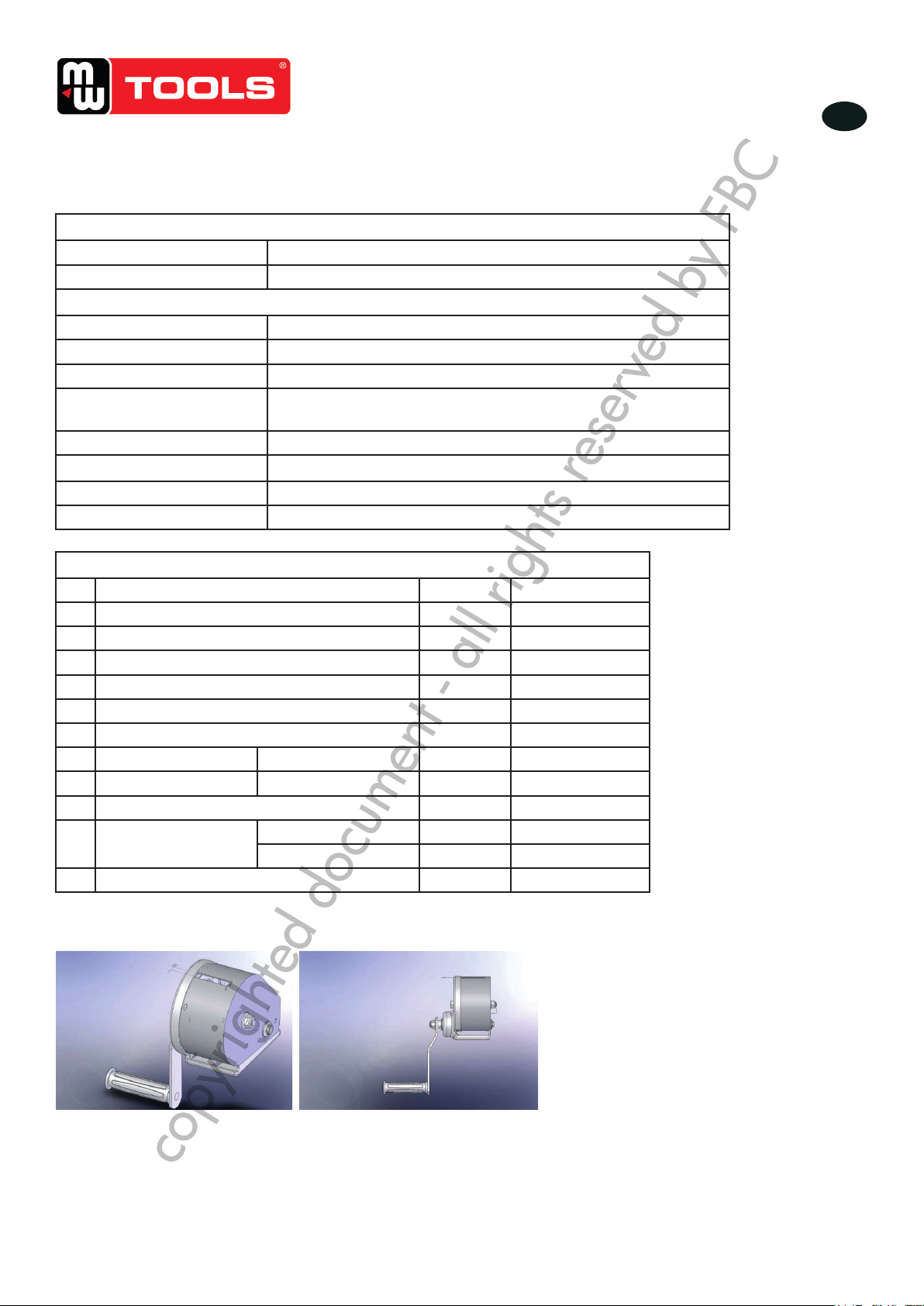
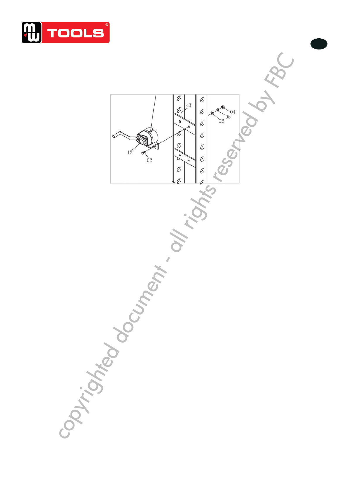
Move the hand winch (12) to the outside of the post, then use bolt (02), washer (06),
lock washer (05), and nut (04) which were dismantled just now to twist tight and fix to
the relevant roller.
Figure 5
3.6 Commissioning the machine
Before the commissioning
Before the first use, please fix the machine to the floor by anchor bole. It must be
ensured that the standing surface of the machine site is firm and horizontal, and that
sufficient lighting is provided for.
Clean the machine thoroughly
Before first use of this product, pour a teaspoon of good quality, air tool lubricant into
the air supply inlet of the lift control valve, connect to air supply to air supply and
5. Verplaats de lier (12) aan de buitenkant van de paal, gebruik vervolgens bout (02), ring (06), veerring (05) en moer
(04) om aan de betrokken rol te bevestigen.
Afb 5
3.5 Ingebruikname
Voor de ingebruikname:
Voor de ingebruikname, veranker de machine aan de ondergrond door middel van trekstangen. Zorg ervoor, dat de
machine goed vastzit en horizontaal is, en dat de verlichting voldoende is.
• Reinig de machine grondig.
• Voor de eerste ingebruikname, giet een kofelepel olie voor luchtdrukwerktuigen in de luchtinlaat van de
controleklep, sluit de luchtverbinding aan met de luchtbron en laat het systeem ongeveer 3 seconden werken, om de
olie regelmatig te verdelen.
• Ontlucht het hydraulisch systeem.
- Manuele werkwijze: open de aaatklep door tegen de klok te draaien. Pomp meermaals volledig om de lucht van
het systeem te verwijderen.
- Perslucht werkwijze: open de aaatklep door tegen de klok te draaien. Sluit de mannelijke snelkoppeling aan met
de vrouwelijke snelkoppeling van de luchttoevoer, open de luchtklep (61) en laat de pomp wat werken om de lucht
van het systeem te verwijderen.
• Controleer alle delen op goede toestand, en indien een van hen beschadigd is, stop de machine en contacteer uw
verdeler.
4 Gebruik
1. Verzeker u ervan, dat het bed goed gepositioneerd is, en bevestig deze door middel van de pins (18).
2. Plaats de stootblok (32) op het frame (31), daarna zet het werkstuk op de stootblok.
Nota: De stootblokken moeten per paar gebruikt worden.
De stootblokken kunnen op beide zijden gebruikt worden.
3. Sluit de aaatklep (P16) door tegen de klok te draaien, totdat deze goed gesloten is.
4. Verbind de luchtslang aansluiting (75) met de luchtbron, open de luchtklep (61) om de pomp te laten draaien totdat
het gekartelde zadel (49) het werkstuk aanraakt, dan sluit de luchtklep. Indien geen luchtbron beschikbaar is, bedien
het handvat (64) om te pompen totdat het gekartelde zadel (49) het werkstuk aanraakt.
5. Het werkstuk en de piston moeten goed uitgelijnd zijn.
6. Open de luchtklep (of bedien het handvat van de pomp) op een druk op het werkstuk uit te oefenen (controleer de
manometer).
7. Wanneer het werk gedaan is, sluit de luchtklep (of stop met pompen), verminder voorzichtig en langzaam de druk
op het werkstuk door de aaatklep (P16) trapsgewijze tegen de klok te draaien.
8. Wanneer de piston volledig ingetrokken is, verwijder het werkstuk van het bed.
9. Ontbind de luchtslang van de luchttoevoer.
copyrighted document - all rights reserved by FBC