SteelMax OSC 8 User manual


Contents
1. GENERAL INFORMATION............................................................................................... 3
1.1. Application................................................................................................................. 3
1.2. Technical data............................................................................................................ 3
1.3. Equipment included ................................................................................................... 4
1.4. Dimensions................................................................................................................ 5
2. SAFETY PRECAUTIONS.................................................................................................. 6
3. STARTUP AND OPERATION........................................................................................... 7
3.1. Assembling................................................................................................................ 7
3.2. Connecting................................................................................................................. 8
3.2.1. To the welding circuit....................................................................................... 8
3.2.1. To the power supply........................................................................................ 9
3.2.2. To the Rail Runner 2 welding carriage............................................................10
3.3. Operating..................................................................................................................12
4. ACCESSORIES...............................................................................................................14
4.1. Freestanding support................................................................................................14
4.2. Power supply............................................................................................................15
5. EXPLODED VIEWS AND PARTS LIST............................................................................16
6. WIRING DIAGRAM..........................................................................................................19
7. DECLARATION OF CONFORMITY.................................................................................20
8. WARRANTY CARD..........................................................................................................21

OSC 8
OSC 8 Operator’s Manual
3
1. GENERAL INFORMATION
1.1. Application
The OSC 8 pendulum oscillator is designed to oscillate MIG/MAG torches with the
diameter of 16–22 mm (5/8–7/8″). The oscillator is installed onto a 22 mm (7/8″)
diameter rod and powered from the welding equipment. Can be controlled manually
or by using an external START-STOP switch.
Using an optional freestanding support allows you to weld pipes that rotate and
plates that move. Using an optional power supply allows you to connect the oscillator
to a 115 V or 230 Vpower source.
The oscillator can also be used on the Rail Runner 2 welding carriage to allow
work with or without seam tracking.
1.2. Technical data
Voltage
14–24 V DC
Power
50 W
Torch type
MIG/MAG
Torch diameter
16–22 mm (5/8–7/8″)
Oscillation type
Pendulum
Oscillation width at r=150 mm (6″)
1–30 mm (1–100%)
1/32–1-3/16″
Oscillation speed at oscillation width of 10 mm (3/8″) and
zero dwell time on ends
12–115 cycles/min (1–100%)
Oscillation dwell time on ends
0–3 s
Maximum torque
8 N·m (5.7 lb·ft)
Protection level
IP 21
Protection class
I
Required ambient temperature
0–50°C (32–122°F)
Weight
2 kg (4 lbs)

OSC 8
OSC 8 Operator’s Manual
4
1.3. Equipment included
1
Oscillator
1 unit
2
2 m (6.5 ft) power cord
1 unit
3
Low rod torch holder with clip
1 unit
4
Arm
1 unit
5
Clamping block
1 unit
6
M6x40 screw
2 units
7
80 mm (3″) rod
1 unit
8
5 mm hex wrench
1 unit
–
Operator’s Manual
1 unit
1
2
3
4
5
7
6
8
OSC 8
OSC 8 Operator’s Manual
5
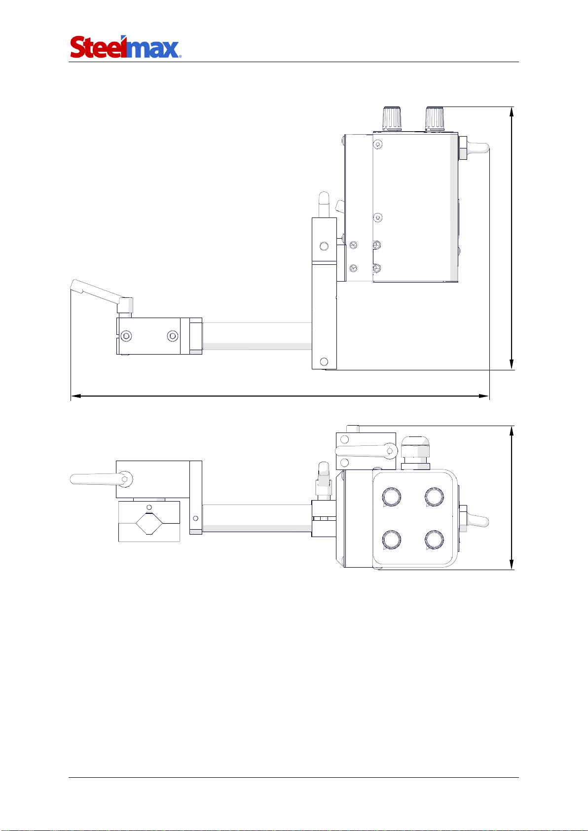
1.4. Dimensions
117 mm (4-5/8″)
215 mm (8-7/16″)
343 mm (13-1/2″)

OSC 8
OSC 8 Operator’s Manual
6
2. SAFETY PRECAUTIONS
1. Before use, read this Operator’s Manual and complete a training in occupational
safety and health.
2. Use only in applications specified in this Operator’s Manual.
3. Make sure that the oscillator has all parts and they are genuine and not damaged.
4. Make sure that the specifications of the power source are the same as those
specified on the rating plate.
5. Do not carry the oscillator by the cord. This can cause damage.
6. Keep the oscillator dry. Do not expose it to rain, snow, or frost.
7. Do not use near flammable materials, or in explosive environments.
8. Connect the power cord only after you set the switch to the middle position.
9. Install only MIG/MAG torches with the diameter of 16–22 mm (5/8–7/8″).
10. Do not stop the oscillator by hand. To stop, set the switch to the middle position.
11. Repair only in a service center appointed by the seller.

OSC 8
OSC 8 Operator’s Manual
7
3. STARTUP AND OPERATION
3.1. Assembling
Use the 5 mm hex wrench to install the clamping block in the chosen position. Point
the arm down, and then install the arm and the torch holder.
INCORRECT
CORRECT
OSC 8
OSC 8 Operator’s Manual
8
3.2. Connecting
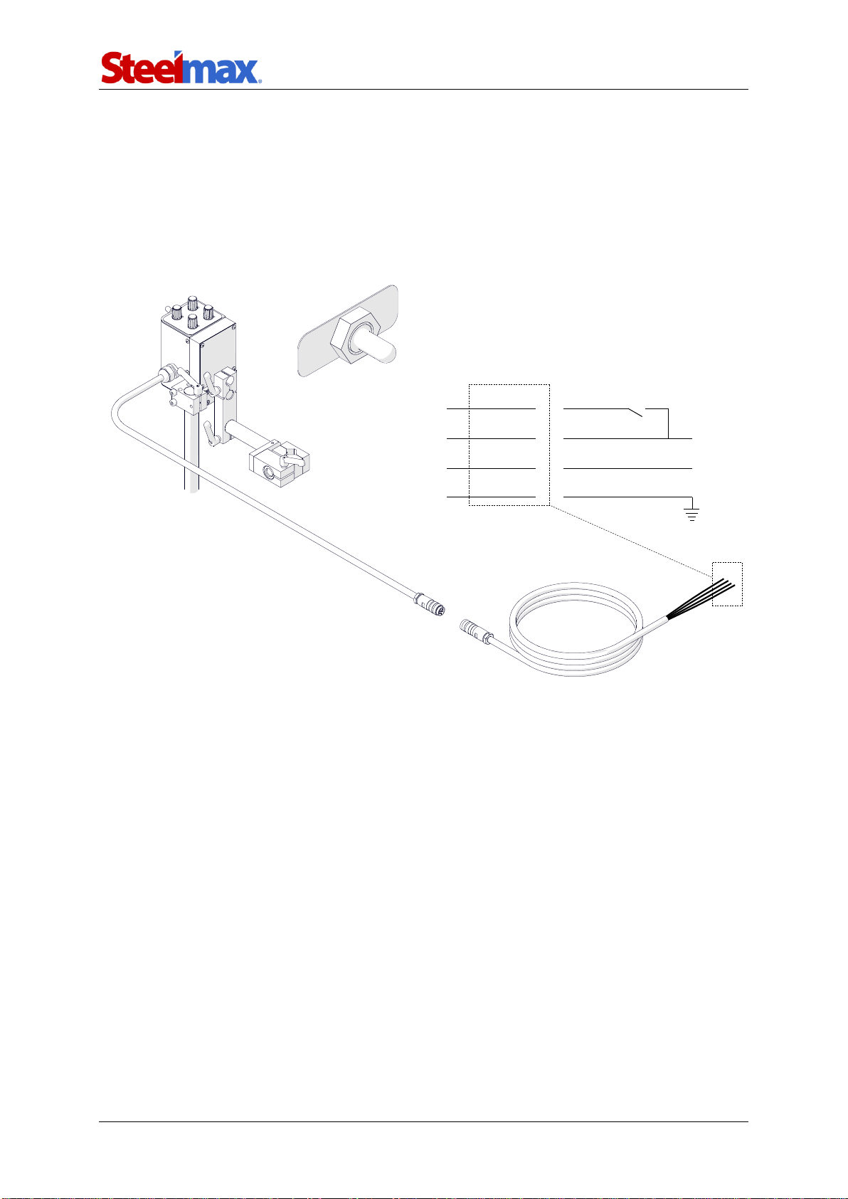
3.2.1. To the welding circuit
Put the oscillator onto a 22 mm (7/8″) diameter rod (1) and set the switch to the
middle position (2). Then, connect the power cord to the welding circuit (3). Next,
connect the power cord to the oscillator (4).
Green
Brown
White
Yellow
Welding circuit
External START-STOP
14–24 V DC
GND
Shield
1
2
3
4
OSC 8
OSC 8 Operator’s Manual
9
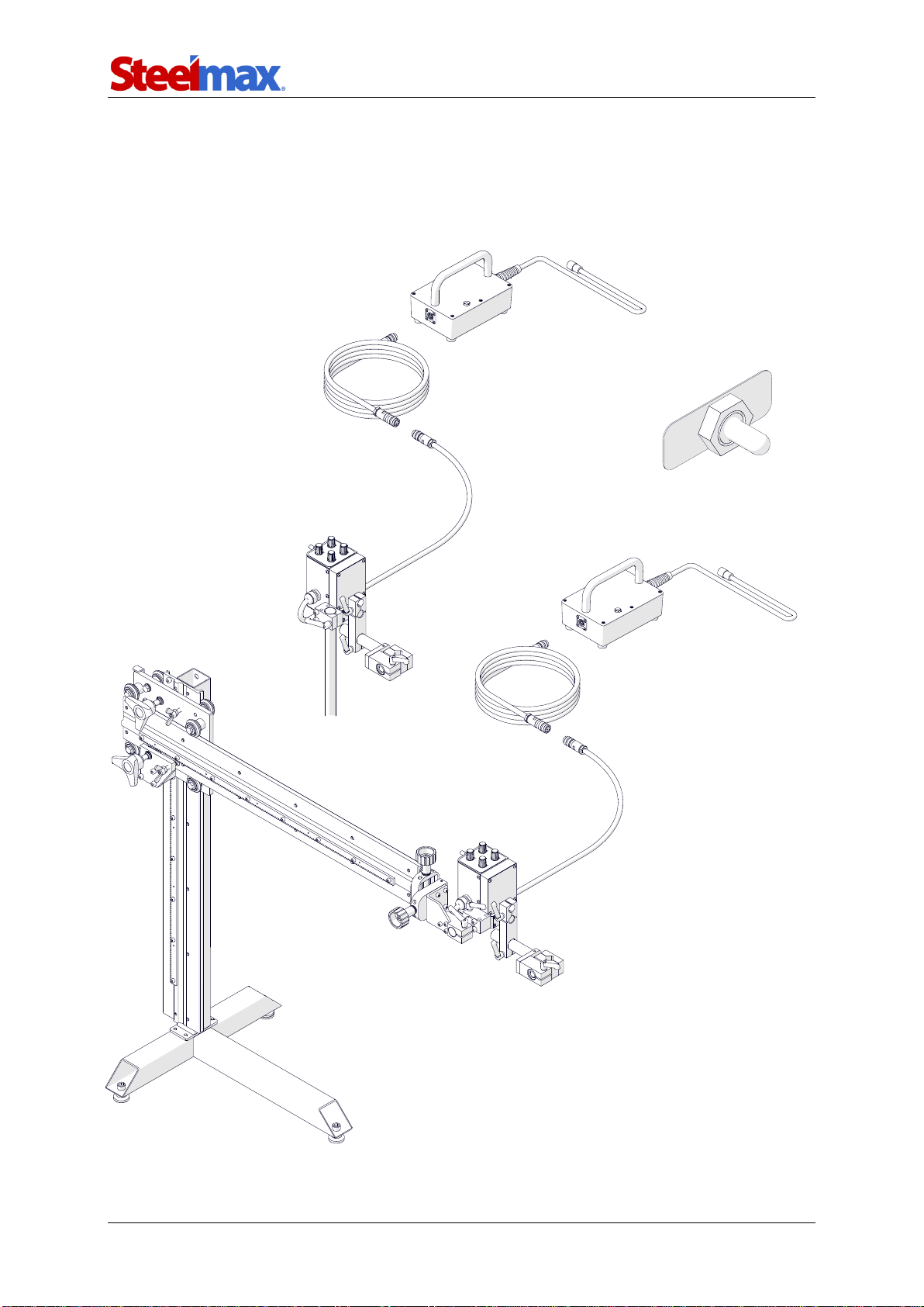
3.2.1. To the power supply
Put the oscillator onto a 22 mm (7/8″) diameter rod (1) or a freestanding support (2,
option). Next, set the switch to the middle position (3). Then, connect the oscillator to
the power supply (4, option).
1
2
3
4
4
OSC 8
OSC 8 Operator’s Manual
10
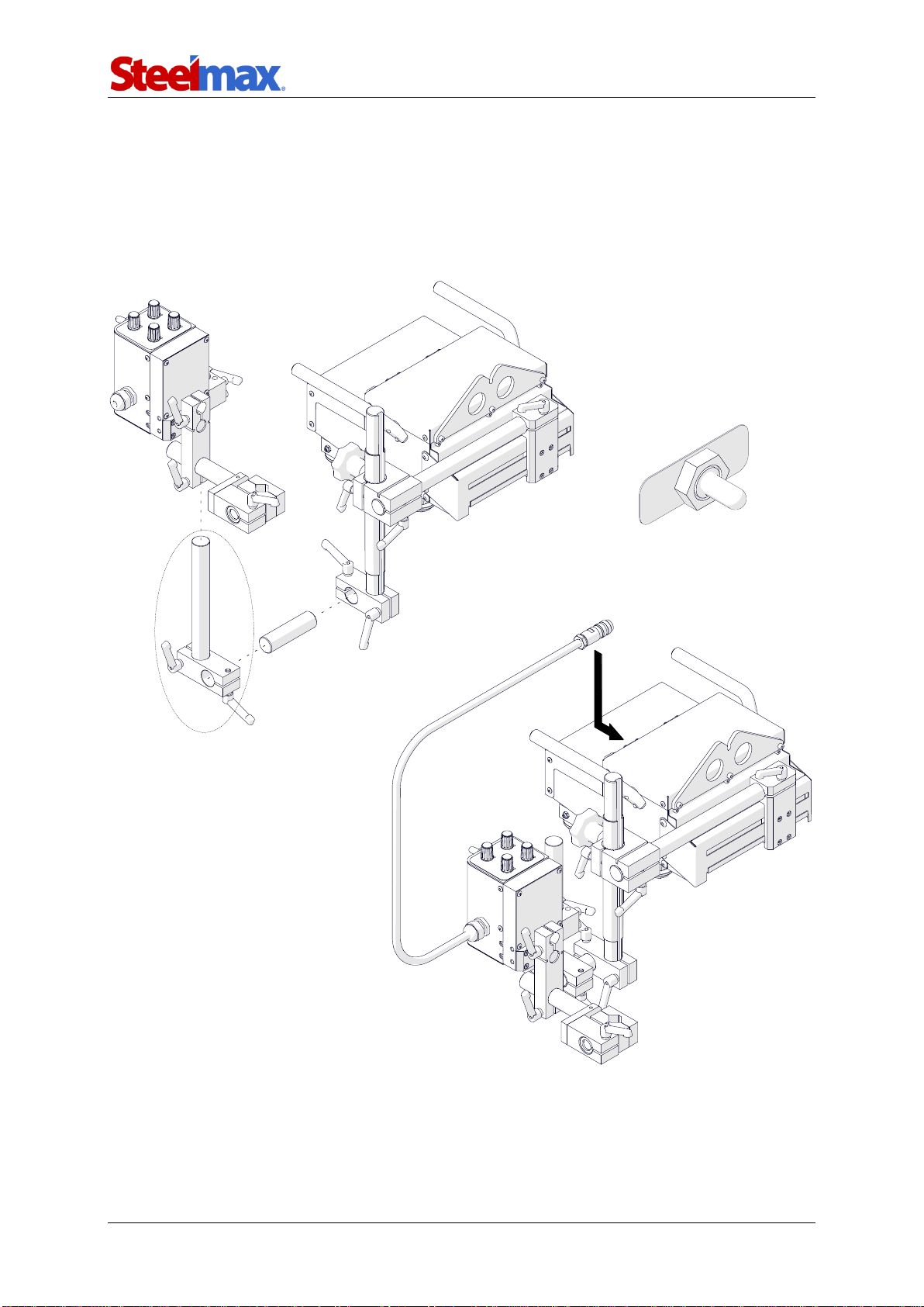
3.2.2. To the Rail Runner 2 welding carriage
To use the oscillator without seam tracking, assembly the oscillator with a 203 mm
(8″) rod and a clamping block (1, option). Then, use the 80 mm (3″) rod to put the
oscillator onto the carriage (2). Next, set the switch to the middle position (3) and
connect the oscillator to the carriage (4).
1
2
3
4
Part number:
KLM-0236-00-16-00-0
(203 mm rod)
KST-0525-11-00-00-0
(Clamping block)

OSC 8
OSC 8 Operator’s Manual
11
To use the oscillator with seam tracking, put the oscillator onto the carriage with the
installed seam tracking attachment (1). Next, set the switch to the middle position (2)
and connect the oscillator to the tracking sensor (3).
2
1
3
OSC 8
OSC 8 Operator’s Manual
12
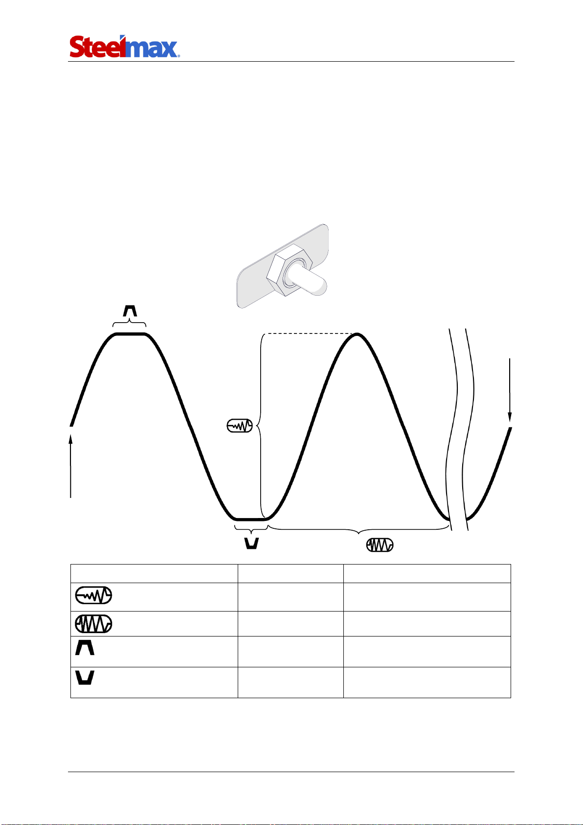
3.3. Operating
Use the knobs to set the required parameters from the table that follows. Then, set
the switch to MANUAL control to start oscillations. To stop oscillations, set the switch
to the middle position.
If the switch is set to EXTERNAL control, oscillations start when a 14–24 V DC is
supplied to the green wire (refer to chapter 3.2.1 for the diagram). To stop oscillations,
use an external START-STOP switch to disconnect the green wire.
Parameter
Value
Description
0–100%
Oscillation width.
0–100%
Oscillation speed.
0–3 s
Oscillation dwell time in the
top position.
0–3 s
Oscillation dwell time in the
bottom position.
Weld
end
Weld
start
1 /
EXTERNAL
MANUAL
OSC 8
OSC 8 Operator’s Manual
13
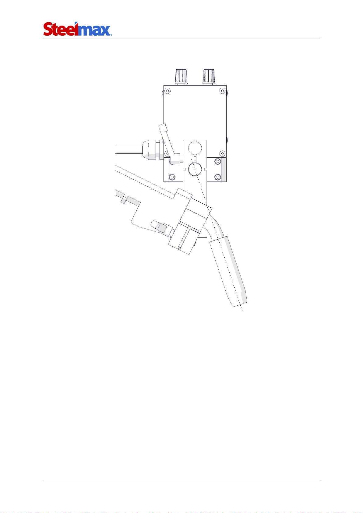
To get the correct shape of oscillation, make sure that the axis of the torch
crosses with the axis of the oscillator’s output shaft.

OSC 8
OSC 8 Operator’s Manual
14
4. ACCESSORIES
4.1. Freestanding support
Allows welding with oscillation of pipes that rotate and plates that move.
Part number:
STJ-0629-24-00-00-0

OSC 8
OSC 8 Operator’s Manual
15
4.2. Power supply
Allows you to connect the oscillator to a 115 V or 230 Vpower source.
Part number:
ZSL-0497-16-00-01-0 (115 V US)
ZSL-0497-16-00-00-0 (230 V CEE)

OSC 8
OSC 8 Operator’s Manual
16
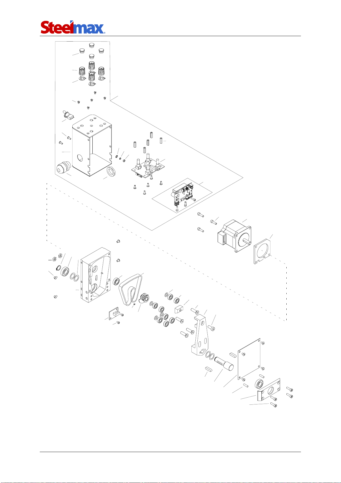
5. EXPLODED VIEWS AND PARTS LIST
6
8
4
5
2
1
3
9
7
ITEM
PART NUMBER
DESCRIPTION
Q-TY
1
RKJ-000043
HANDLEVER M6-25
1
2
UCW-0497-13-00-00-0
CLAMP
1
3
SRB-000124
HEX SOCKET HEAD CAP SCREW M6x40
2
4
KLC-000008
5 MM HEX WRENCH
1
5
RAM-0477-01-10-00-0
OSCILLATOR ARM ASSY
1
6
UCW-0476-06-00-00-0
TORCH HOLDER LOWER ROD CLAMP ASSY
1
7
RKJ-000036
HANDLEVER M6-32
1
8
TLJ-0419-04-02-03-0
INSULATION TUBE
1
9
WSP-0497-17-00-00-0
SUPPORT
1
10*
WZK-0497-14-00-00-0
POWER SUPPLY WIRE SET
1
* not shown in the drawing
OSC 8
OSC 8 Operator’s Manual
17
8
7
9
10 17
1
11
6
12 13 14
4
3
16
25
15
2
18 19
23 24
21
20
26
27 28
22
32
31
33 34
29
30
35 36 37
40
39
38
42 43
41
44

OSC 8
OSC 8 Operator’s Manual
18
ITEM
PART NUMBER
DESCRIPTION
Q-TY
1
OBD-0497-09-00-00-0
HOUSING ASSY
1
2
ZLP-000020
CAP
4
3
PKT-000027
KNOB
4
4
WSK-000008
KNOB INDICATOR
4
6
WKR-000372
COUNTERSUNK HEAD SCREW M3x5
5
7
WZK-0497-09-02-00-0
TRAVEL DIRECTION SWITCH WIRE SET ASSY
1
8
WKR-000313
HEX SOCKET BUTTON HEAD SCREW M3x8
7
9
OBD-0497-09-01-00-0
HOUSING
1
10
WZK-0497-09-03-00-0
POWER CORD WIRE SET
1
11
NKR-000040
STRAIN RELIEF NUT
1
12
PDK-000058
EXTERNAL TOOTH LOCK WASHER 3.2
1
13
PDK-000041
SPRING WASHER 3.1
1
14
NKR-000009
HEX NUT M3
1
15
TLJ-000122
DISTANCE SLEEVE
5
16
MDL-0497-09-07-00-0
MODULE
1
17
MDL-0497-09-06-00-0
OSCILLATOR MODULE ASSY
1
18
SRB-000063
HEX SOCKET HEAD CAP SCREW M4x14
3
19
SLN-0497-10-00-00-0
MOTOR
1
20
DYS-0497-04-00-00-0
MOTOR PLATE
1
21
NKR-000139
LOW HEX NUT M6
2
22
WKR-000292
HEX SOCKET BUTTON HEAD SCREW M4x6
8
23
PRS-000003
EXTERNAL RETAINING RING 12z
1
24
LOZ-000085
BALL BEARING 12x24x6
2
25
PDK-000178
WASHER 12x18x0.2
4
26
KRP-0497-01-00-00-0
BODY
1
27
LOZ-000123
BALL BEARING 10x19x5
1
28
PAS-000013
TOOTHED BELT 130XL037
1
29
WZK-0497-11-00-00-0
TRANSOPTOR WIRE SET
1
30
WKR-000180
CROSS RECESSED PAN HEAD SCREW M3x5
2
31
WKR-000484
HEX SOCKET SET SCREW WITH FLAT POINT M3x3
1
32
KOL-0497-02-00-00-0
MOTOR GEAR ASSY
1
33
PDK-000155
SMALL ROUND WASHER 6.4
4
34
LOZ-000110
BALL BEARING 6x15x5
8
35
DCS-0497-07-00-00-0
BELT HOLDER
1
36
SRB-000386
HEX SOCKET ULTRA LOW HEAD CAP SCREW M6x20
4
37
WDZ-0497-03-00-00-0
CROSSHEAD
1
38
SRB-000301
LOW HEAD HEX SOCKET CAP SCREW M6x14
1
39
WPS-000033
PARALLEL KEY 5x5x20
2
40
WLK-0497-05-00-00-0
SHAFT
1
41
OSL-0497-08-00-00-0
FRONT COVER
1
42
KLK-000034
DOWEL PIN 4n6x14
2
43
OPR-0497-06-00-00-0
BEARING MOUNTING
1
44
SRB-000063
HEX SOCKET HEAD CAP SCREW M4x14
4

OSC 8
OSC 8 Operator’s Manual
19
6. WIRING DIAGRAM

OSC 8
OSC 8 Operator’s Manual
20
7. DECLARATION OF CONFORMITY
Declaration of Conformity
PROMOTECH sp. z o.o.
ul. Elewatorska 23/1
15-620 Białystok
Poland
We declare with full responsibility that:
OSC 8 Pendulum Oscillator
is manufactured in accordance with the following standards:
•EN 12100
•EN 60204-1
•EN 60974-10
and satisfies regulations of the guidelines: 2004/108/EC, 2006/95/EC, 2006/42/EC.
Person authorized to compile the technical file:
Marek Siergiej, ul. Elewatorska 23/1, 15-620 Białystok, Poland
Białystok, 5 September 2016 ___________________________
Marek Siergiej
CEO
Table of contents


