Keller HPX User manual

Operating instructions for the
high pressure calibrator (HPX)

View 13
Notes on the operating instructions 14
1. Description of the device 14
2. General safety warnings 14
3. Operating the HPX calibrator 15
4. Description of the functions 15
5. Menu navigation for calibrators 16
6. Commissioning 16
7. Maintenance / disposal 17
8. Software for calibrators 18
Technical data 19
Spare parts and accessories for KELLER pressure calibrators 20
Declaration of conformity 31
Table of contents

13
View
2110 34 6 5711 8 9
1 Port for interface cable (K-104A or K-114A)
(PC connection / RS485)
2 Device base
3 Display
4 SELECT and ENTER buttons
5 Oil chamber
6 Recirculation pipe
7 Screwed sealing plug
8 Manual booster pump
9 Pressure connection for test object, without overpressure valve
(700 bar)
10 Drain valve
11 Screw compressor

14
Notes on the operating instructions
- The operating instructions are in-
tended for specialist workers and
trained personnel.
- Before each stage of work, read the
relevant notes and warnings care-
fully, and keep to the sequence as
stated.
- Pay particular attention to the sec-
tion on ”General safety warnings”.
If you have any problems or questions,
please contact your supplier or
consult KELLER directly.
1. Description of the device
General description
The high pressure calibrator enables
pressure to be generated by means of
the integrated pressure pump, up to
700 bar relative.
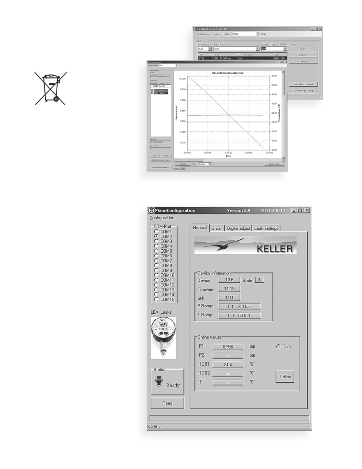
The measurement technology incor-
porated into this device allows ac-
curate measurement and documen-
tation of the characteristic of a test
object that is connected to it. The
measured pressure progression can
be displayed, evaluated and saved
with a computer monitoring program
(CCS30).
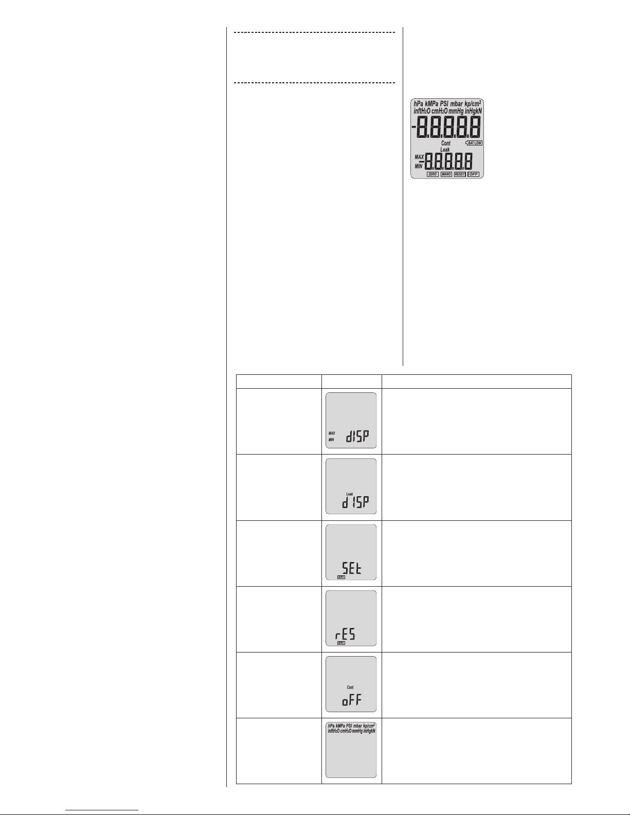
The calibrator is operated with the
two function buttons SELECT and
ENTER, located directly below
the display. The calibrator itself is
powered by a 3,0 V battery, but power
can also be supplied externally via the
K-114A interface converter. Test ob-
jects (transmitters or pressure switch-
es) must be supplied from an external
source.
Pressure range for the display
High pressure calibrators are them-
selves calibrated with the ambient air
pressure as the zero point reference.
The Zero function allows any desired
pressure value to be set as the new
zero point reference.
To take relative measurements,
the high pressure calibrator is
zeroed at ambient pressure (Set
Zero). To reset the pressure zero
point to the factory setting, use the
RES Zero function (reset zero).
Commissioning
A pressure-resistant connection for
the test object is required in order to
use the high pressure calibrator. The
pressure connection for the test object
is already screwed to the pressure
distributor of the high pressure calibra-
tor so that it is pressure resistant when
it leaves the factory, and it must not be
dismantled.
Recommended torque for the test
object pressure connection: 30 Nm
IMPORTANT!
Nothing must adhere to the surface of
the test object (no oil, grease, water,
etc). Impurities could pass through the
adapter to reach the high pressure
calibrator and damage it.
Overpressure
If the pressure exceeds the measuring
range by more than 20%, the measur-
ing cell or the mechanism of the high
pressure calibrator may be destroyed.
Recalibration
The recalibration cycle depends on
the conditions of use. Recommended
recalibration cycle: 1 year.
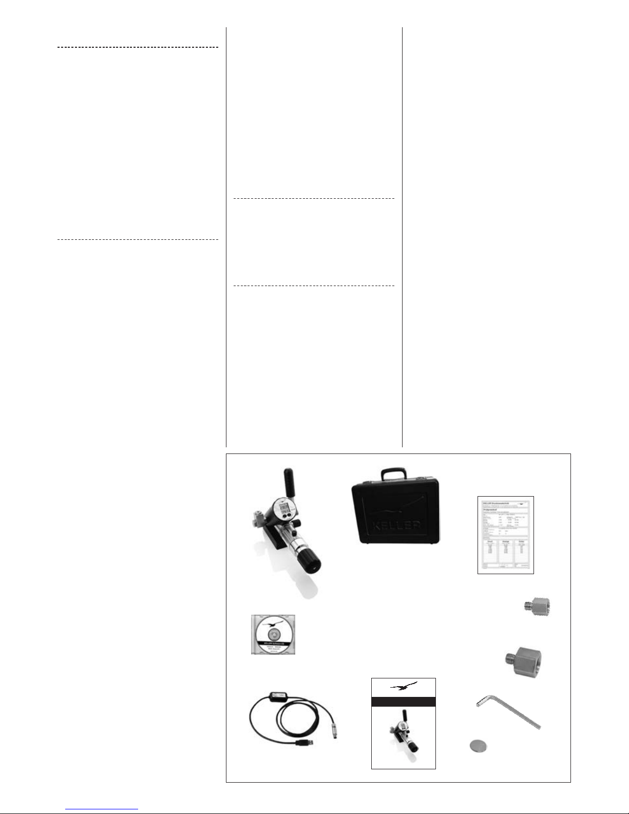
Scope of delivery
- 1calibrator(includingoillling)
- 1 carrying case
- 1 test record (5 points)
- 1testobjectadapterG1/4”–G1/8”
- 1testobjectadapterG1/4”–G1/2”
- 1 Allen key
-
1 spare battery, type CR2430 (3,0 V)
- 1 set of operating instructions
- 1 USB interface converter, K-114A
- 1 KELLER software CD
Intended use
The high pressure calibrator (HPX)
may only be used to generate pres-
sure with the type HLP 22 BP hydrau-
lic oil that is supplied with the product.
Use of the calibrator with other media
will damage it. The operational safety
of the device supplied is guaranteed
only if it is used as intended. The limit
values as stated (see page 19: ”Tech-
nical data”) must never be exceeded.
Before installing the high pressure
calibrator, check that it is suitable for
your applications.
2. General safety warnings
The current national regulations on
accident prevention and workplace
Operating instructions for the
high-pressure calibrator (HPX)
October 2012
Scope of delivery
High pressure calibrator

15
safety must be followed whenever
work is carried out. Internal regula-
tions issued by the operator must
be followed, even if they are not
mentioned in these instructions.
Never use the high pressure calibra-
tor together with an external pressure
source.
Do not remove any connected compo-
nents (e.g. test objects) when the high
pressure calibrator is under pressure.
Open the screwed sealing plug before
removing parts.
Do not use Teon tape to seal the
pressure connection.
Residues of
Teontapecouldpenetratethehigh-
pressure calibrator and damage it.
Only use the adapters and seals that
are available as accessories.
Do not store the calibrator under pres-
sure: only store the high pressure cali-
brator with the drain valve open.
Avoid the action of force of any kind
on the high pressure calibrator and its
operating controls.
Do not use high pressure calibrators if
they are damaged or faulty.
3. Operating the HPX calibrator
Operating the high pressure calibrator
is described starting on page 16.
Connect the test object
You can connect your test object to the
high pressure calibrator via the pres-
sure connection (9).
Pressure generation
When using the calibrator, the screwed
sealing plug (7) must be opened (2
turns), so that overpressure cannot
build up in the oil reservoir.
Use the manual booster pump (8) to
set the pressure to about 10 bar. You
can use the screw compressor (11) to
increase or reduce the pressure.
Release pressure
1.
Open the screw compressor (11)
completely
2. Open the drain valve (10)
IMPORTANT!
Do not open if there is high pressure in
the system!
If you can no longer reach the desired
pressure, please consult the section on
"Maintenance"tondouthowtovent
the system.
Zeroing the device
Open the drain valve (10) to release
any pressure that may have built up.
If the pressure display does not show
zero, perform a zeroing procedure
(Set Zero) and then close the drain
valve.
Information about the display
If no pressure can be shown on the dis-
play, it will show OFL(overow)orUFL
(underow).
If pressure outside the device’s
measuring range is applied, the
last valid pressure value that was
measured will ash on the display
(overload warning).
Reset
4. Description of the functions
Menu navigation
If the selected function or unit is not ac-
tivated by pressing the ENTER button
within 5 seconds, the display will return
to measuring mode without changing a
setting.
Function
Reset
Description
Min. / max. display Shows the peak and trough pressure values
measured thus far.
(Display is shown with reduced resolution)
Leak measurement Leak mode is used to determine the pressure
change over a dened period, which can be
changed.
(Leak measurement period, factory setting:
10 minutes)
Zero the display Permanently sets the applied pressure as the new
pressure zero point.
Reset
display
Resets the pressure zero point to the factory set-
ting.
Automatic
switch-off function
(Cont = Continuous) The device switches off
automatically after a dened period (which can
be changed), starting from the last time a button
was pressed. (Switch-off period, factory setting:
15 minutes)
Select units mbar, bar, hPa, kPa, MPa, cmH2O, mH2O, inH2O,
ftH2O, PSI, kp/cm2, mmHg, inHg

6. Commissioning
Switch the device on
Press the SELECT button to switch the
device on. Initially, the device shows
the pressure range calibrated in the
factory (top) and the software version
(year / week).
Switch the device off
Keep the SELECT button pressed
down until the display shows OFF.
Press the ENTER button to execute
the shutdown.
➞The settings made previously are
retained when you switch the device
on and off.
Display mode
Display mode is the calibrator’s basic
mode. The upper part of the display
shows the pressure unit and the pres-
sure that is currently measured. The
lower part of the display shows the last
function that was used, either the min./
max. display or the Leak function.
Using the functions
Written descriptions of the individual
functions are given below (in addition
to the diagram above).
Selecting functions
The individual sub-functions are called
up
from the MANO menu. Keep the
SELECT button pressed until MANO is
SELECT button
The SELECT button positioned on the
front is used to switch the device on,
to select a function and to select the
various pressure units.
ENTER button
The ENTER button positioned on
the front is used to activate the se-
lected function or pressure unit on the
device.
You can also press the ENTER
button to switch between the minimum
and maximum pressure values
measured thus far.
Menu navigation for calibrators
SELECT button
E
N
T
E
R
b
u
t
t
o
n
❶ Resetting peak- and trough pressure
❷ Min. / max. display
❸ Leak measurement
❹ Set zero point permanently
❺ Reset zero point to factory setting
❻ Activate / deactivate switch-off function
❼ Select units
❶❷
❸
❹❺
❻❼
➞Pressure unit
➞Current measured value
➞Pressure change within
leak runtime
➞Leak runtime in mm:ss
➞
5. Menu navigation for calibrators
16

shown, and press ENTER to activate.
You can now use SELECT to choose
the function you want, and ENTER to
execute the function. Depending on
the current setting, the rst function
to be shown is either min/max disp or
LEAK disp.
Leak measurement function
Leak mode is used to determine
the pressure change over a dened
period, which can be adjusted. The
unit to be tested must be connected
to the high pressure calibrator on the
pressure side.
Start leak measurement
Activate the MANO menu. The display
shows Leak dISP. Press the ENTER
button and
then the SELECT button.
PressENTERtoconrm Leak Start.
The leak measurement starts, and the
display alternates between the current
leak time and the pressure change
measured thus far.
Active leak measurement
During leak measurement, the lower
part of the display alternates each sec-
ond between the measurement time
that has now elapsed [mm:ss] and the
pressure change measured thus far.
End leak measurement early
To end a leak measurement early,
presstheENTERbuttonandconrm
the ”Leak Stop” display by pressing
ENTER.
Leak measurement completed
If the leak measurement time has
elapsed or if the measurement was
manually ended ahead of time,
the display alternates between the
elapsed leak measurement time and
the measured pressure change.
Set leak measurement time
The leak measurement time is preset
to 10 minutes in the factory, and it can
only be changed with the ”Mano Con-
g”software.
(➞Software for calibrators)
MANO / "Continuous" function
Automatic switch-off function (the de-
vice switches off automatically 15 mi-
nutes after a button was last pressed).
Leak measurements are canceled by
the automatic switch-off function if the
measurement time is more than the
switch-off time.
Cont on:Disables the automatic
switch-off function
Cont oFF:Enables the automatic
switch-off function
If the "Continuous" function is en-
abled, Contashesonthedisplay.
➞Mano mode
➞Launch Leak
mode by press-
ing the ENTER
button
7. Maintenance / disposal
Venting the pressure system
Release the pressure completely and
then open the drain valve (10) and the
screwed sealing plug (7). Screw the
screw compressor (11) in completely.
Pump steadily with the manual boos-
ter pump (8) to clear the system of air.
When no more bubbles come out of
the recirculation pipe (6), close the
drain valve (10).
Changing the oil
We recommend that you have
KELLER change the oil. The entire
system is cleaned at the same time.
Only use type HLP 22 BP hydraulic oil.
Battery
The pressure calibrator is powered
by a 3 V button-cell battery (behind
the display). If the battery is low, the
battery symbol on the display
lights up.
Replacing the battery
Please switch the device off. Turn the
display section ring beyond the limit
stop until it is released from the hous-
ing section (turn through about 180°).
Open the battery compartment and
change the battery (type CR 2430).
➞Start the leak
measurement
with ENTER
ENTER
ENTER
ENTER
KELLER
S
E
L
E
C
T
E
N
T
E
R
w
w
w
.
k
e
l
l
e
r
-
d
ru
c
k
.
c
h
s
w
i
s
s
m
a
d
e
M
a
x
.
/
M
i
n
.
17
➞Unit of pressure
➞Current
measured value
Leak run-
time in
mm:ss ➞
➞Unit of pressure
➞Current
measured value
Leak run-
time in
mm:ss ➞➞
Pressure change
within leak
runtime
Pressure change
within leak
runtime
➞
➞
(8)
(10)
(7)
(11)

Disposal
This product must not be disposed of
as normal household waste at the end
of its useful lifetime. To prevent pos-
sible damage to the environment or
to health due to uncontrolled waste
disposal, this product
must be separated
from other waste and
recycled correctly in
order to ensure sus-
tainable use of the raw
materials.
8. Software for calibrators
The USB interface converter (K-114A)
enables communication between the
calibrator and a computer. Before
you connect the interface converter
to the computer, install driver K-104
/ K-114 (the software CD is included
in the scope of delivery, K-114A, or
can be downloaded free of charge at
www.keller-druck.com)
Settings on the high pressure
calibrator with the ManoCong
software
Device settings such as the leak
measurement time or the switch-off
time for the pressure calibrator can
be adjusted using the "ManoCong"
software.
Record measurements with the
CCS30 software
The CCS30 software records the data
measured
by the pressure calibra-
tor, and shows them in both graphic
and tabular form. Measured data can
be saved or exported for further pro-
cessing. You will nd more informa-
tion about the software in the CCS30
manual.
Step-by-step software installation
Install from the CD or from
www.keller-druck.com:
1.) K-104 / K-114 driver
2.) (CCS30) Control Center Series 30
3.)ManoCong(ifdesired)
18
ManoCong
Control Center
CCS30

Pressure range (FS) 0…700 bar (others on request)
Overpressure 840 bar
Accuracy, error band (1) (10…40 °C) < 0,05 %FS
Accuracy, error band (1) (0…50 °C) < 0,1 %FS
Leak rate* 700 bar: -2 bar @ 10 min.
Display resolution 1 mbar
Number of digits on display 5 digits
Measurement interval 0,5 seconds
Interface RS485; the Fischer cable socket on the side fits the K-104A / K-114A
interface converter
Compensated temperature range 0…50 °C
Operating temperature 0…50 °C
Storage temperature -10…60 °C
Air humidity 5…95% relative humidity
Power supply Button-cell battery, type CR2430
Battery lifetime: > 2000 h in continuous operation
Hydraulic oil HLP 22 BP
Dimensions (L x W x H) 315-337 x 155 x 148 mm
Degree of protection IP 65
Selectable pressure units bar, mbar, hPa, kPa, MPa, PSI, kp/cm2, cmH2O, mH2O, inH2O, ftH2O,
mmHg, inHg
(1) including accuracy, temperature coefficients, zero point and range tolerance
* Physical effects caused by a pressure change lead at first to a clear difference in pressure.
Advice: To minimise the influence of these physical effects increase steadily the last 5% of the target pressure and regulate towards the target
pressure for the first minutes.
The stated leakage rate is at a thermal balanced condition (when temperature of pressure media and of the environment is equable).
Technical data
19

Description Article number LPX MPX HPX Illustration
Carrying case, empty 309025.0005 x x x
Battery, type CR2430 557005.0001 x x x
Hose nipple 508832.0005 x x
Connecting nipple, G 1/4”
including sealing ring
508832.0004 x x
Y-coupler 307025.0001 x
Test object adapter,
G 1/4”M-G 3/8”F
506810.0028 x
Test object adapter,
G 1/4”M-G 1/2”F
506810.0013 x
Sealing ring, G 1/8” 508635.0001 x x
Sealing ring, G 1/4” 508635.0002 x x
CrNilter 307025.2011 x x
Vacuum pump 309005.0005 x x
Hand pump 309005.0004 x
Fine-tuning valve 309030.0006 x x
Bottle of oil, 0,5 l
(HLP 22 BP hydraulic oil)
650505.0005 x
K-114A 309010.0075 x x x
Spare parts and accessories for KELLER pressure calibrators
20
suitable for

Konformitätserklärung Declaration of Conformity Déclaration de Conformité
Für das folgenden Erzeugnis…
Hochdruckkalibrator
HPX
…wird hiermit bestätigt, dass
es den wesentlichen Schutzan-
forderungen entspricht, die in der
Richtlinie des Rates zur Angleichung
der Rechtsvorschriften der Mitglied-
staaten über die elektromagne-
tische Verträglichkeit (2004/108/EG)
festgelegt sind.
Diese Erklärung gilt für Produkte die-
ser Serie, die mit dem CE-Zeichen
versehen und die Bestandteil dieser
Erklärung sind.
Zur Beurteilung der Erzeugnisse hin-
sichtlich elektromagnetischer Ver-
träglichkeit wurden folgende Normen
herangezogen.
Diese Erklärung wird verantwortlich
für den Hersteller:
abgegeben durch die
EN 61326-2-3:2006
KELLER AG für Druckmesstechnik, St. Gallerstrasse 119, CH-8404 Winterthur
KELLER GmbH, Schwarzwaldstrasse 17, D-79798 Jestetten
Herewith we declare that the following
product or product range
High pressure calibrator
HPX
meet the basic requirements for the
electromagneticcompatibility,whichare
established in the directive of the
European Community (2004/108/EC).
This declaration is valid for products
of this Series marked with the CE sign
and which are part of this declaration.
As criteria for the electromagnetic
compatibility, the following norm is
applied:
This declaration is given for the manu-
facturer
in full responsibility by
Nous attestons que le produit ou
gamme de produits :
Calibrateur haute pression
HPX
répondent aux exigences de base en
matière de compatibilité électromag-
nétique prévues par la directive de la
Communauté Européenne (2004/108/
CE).
La présente déclaration est valable
pour les produits de cette série, mar-
qués avec le sigle CE et faisant partie
intégrante de la présente déclaration.
La norme appliquée pour évaluer la
compatibilité électromagnétique des-
dits instruments est la suivante :
La présente déclaration est fournie
pour le fabricant
par
Jestetten, 4. Oktober |October |Octobre 2012
Hannes W. Keller
Geschäftsführender Inhaber |Managing Owner |Président Directeur Général
mit rechtsgültiger Unterschrift |with legally effective signature |dûment autorisé à signer

KELLER AG für Druckmesstechnik
St.Gallerstrasse119•CH-8404Winterthur
Tel.+41(0)522352525•Fax+41(0)522352500
www.keller-druck.com November•November•Novembre2012
Table of contents
Other Keller Test Equipment manuals