Broan ERV100SP Series User manual

*This product earned the ENERGY STAR®by meeting strict energy efficiency guidelines set by Natural Resources Canada and the
US EPA. They meet ENERGY STAR requirements only when used in Canada.
22634 rev. 05
INSTALLATION GUIDE FOR
BROAN ERV100S AND ERV100SP
RESIDENTIAL USE ONLY
READ AND SAVE THESE INSTRUCTIONS
! !
Model ERV100S
VB0198
Model ERV100SP*
VB0197
Broan-NuTone LLC; Hartford, Wisconsin www.broan.com 800-543-3055
REGISTER YOUR PRODUCT ONLINE AT: www.broan.com/register
For additional information - visit www.broan.com

2
WARNING
!
Please take note that this manual uses the following symbols to emphasize particular information:
NOTE: Indicates supplementary information needed to fully complete an instruction.
CAUTION
Identifies an instruction which, if not followed, may severely damage the unit and/or its components.
ABOUT THIS MANUAL
ABOUT THESE UNITS
LIMITATION
For residential (domestic) installation only. Installation work and electrical wiring must be done by a qualified person(s) in accordance with
all applicable codes and standards, including fire-rated construction codes and standards.
TO REDUCE THE RISK OF FIRE, ELECTRIC SHOCK, OR INJURY TO PERSON(S) OBSERVE THE FOLLOWING:
1.Use this unit only in the manner intended by the manufacturer. If you have questions, contact the manufacturer at the address or
telephone number listed in the warranty.
2. Before servicing or cleaning the unit, disconnect power cord from electrical outlet.
3. This unit is not designed to provide combustion and/or dilution air for fuel-burning appliances.
4. When cutting or drilling into wall or ceiling, do not damage electrical wiring and other hidden utilities.
5. Do not use this unit with any solid-state speed control device other than following controls:
6. This unit must be grounded. The power supply cord has a 3-prong grounding plug for your personal safety. It must be plugged into a
mating 3-prong grounding receptacle, grounded in accordance with the national electrical code and local codes and ordinances. Do
not remove the ground prong. Do not use an extension cord.
7. Do not install in a cooking area or connect directly to any appliances.
8. Do not use to exhaust hazardous or explosive materials and vapors.
9. When performing installation, servicing or cleaning these units, it is recommended to wear safety glasses and gloves.
10. When applicable local regulation comprise more restrictive installation and/or certification requirements, the aforementioned
requirements prevail on those of this document and the installer agrees to conform to these at his own expenses.
CAUTION
1. To avoid prematurate clogged filters, turn OFF the unit during construction or renovation.
2. Please read specification label on product for further information and requirements.
3. Be sure to duct air outdoor – Do not intake/exhaust air into spaces within walls or ceiling or into attics, crawl spaces, or garage.
4. Intended for residential installation only in accordance with the requirements of NFPA 90B.
5. Do not run any air ducts directly above or closer than 2 ft to any furnace or its supply plenum, boiler, or other heat producing appliance.
If a duct has to be connected to the furnace return plenum, it must be connected not closer than 9’ 10” from this plenum connection to
the furnace.
6. The ductwork is intended to be installed in compliance with all local and national codes that are applicable.
7. When leaving the house for a long period of time (more than two weeks), a responsible person should regularly check if the unit
operates adequately.
8. If the ductwork passes through an unconditioned space (e.g.: attic), the unit must operate continuously except when performing
maintenance and/or repair. Also, the ambient temperature of the house should never drop below 65°F.
UNIT MAIN CONTROL AUXILIARY CONTROLS
ERV100SP VT8W, VT7W, VT4W OR VT6W VB60W AND 59W
ERV100S VT7W, VT4W OR VT6W VB20W AND 59W
WARNING
Identifies an instruction which, if not followed, might cause serious personal injuries including possibility of death.
!

3
TABLE OF CONTENTS
1. T YPICAL INSTALLATIONS ......................................................................................................................... 4-5
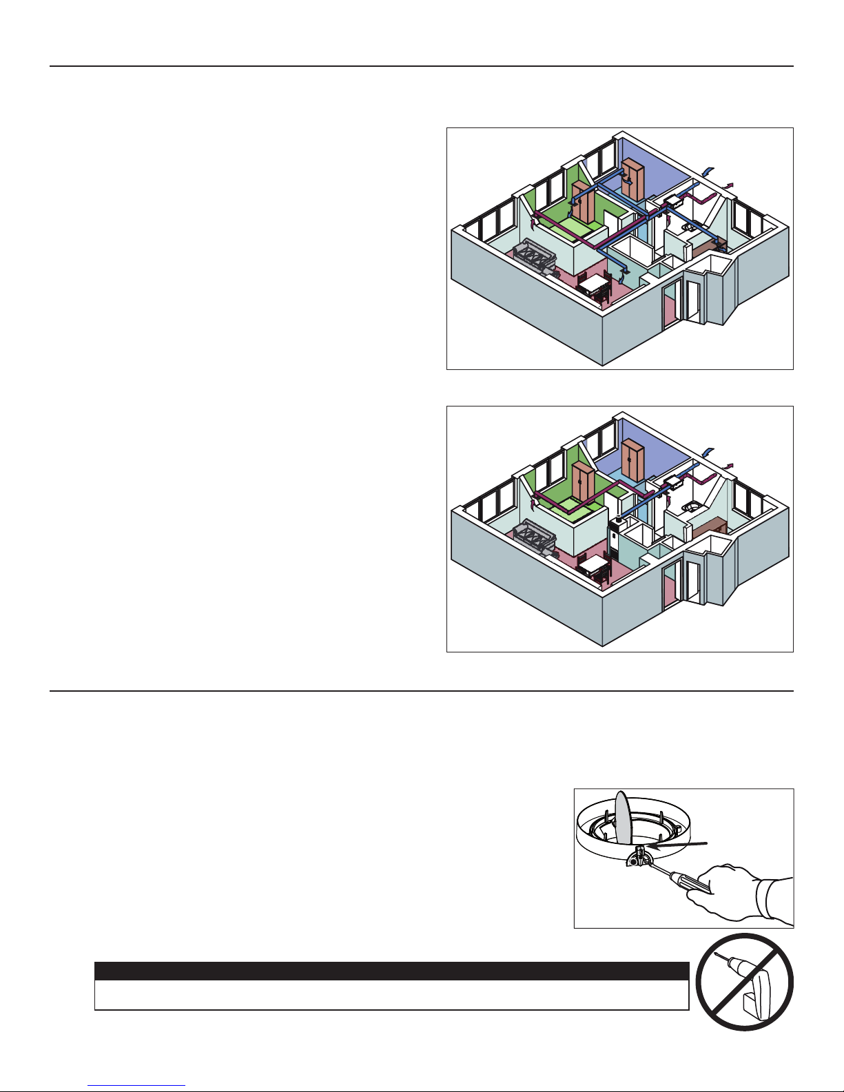
1.1 FOR HOUSE .................................................................................................................................................. 4
1.1.1 FULLY DUCTED SYSTEM............................................................................................................................................4
1.1.2 CENTRAL DRAW POINT.............................................................................................................................................4
1.1.3 SIMPLIFIED INSTALLATION...........................................................................................................................................4
1.2 FOR HIGH-RISE DWELLING .............................................................................................................................. 5
1.2.1 FULLY DUCTED SYSTEM ...........................................................................................................................................5
1.2.2 CENTRAL DRAW POINT ............................................................................................................................................5
2.INSTALLATION..................................................................................................................................... 5-12
2.1 INSPECT THE CONTENT OF THE BOX .................................................................................................................. 5
2.2 UNIT PREPARATION ......................................................................................................................................... 5
2.3 LOCATING THE UNIT ........................................................................................................................................ 6
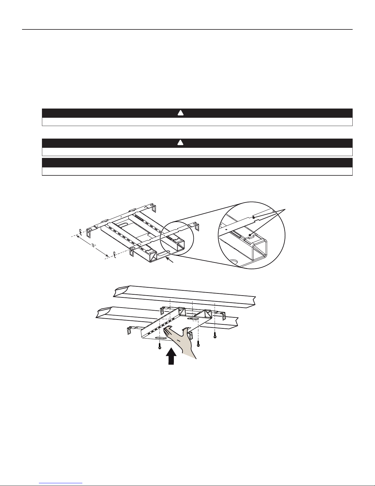
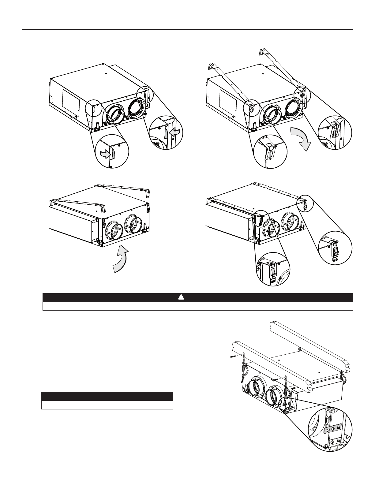
2.4 HOW TO HANG THE UNIT ..............................................................................................................................6-8
2.5 PLANNING OF THE DUCTWORK .......................................................................................................................... 8
2.6 INSTALLING THE DUCTWORK AND REGISTERS ................................................................................................. 8-10
2.6.1 FULLY DUCTED SYSTEM...........................................................................................................................................8
2.6.2 CENTRAL DRAW POINT............................................................................................................................................9
2.6.3 SIMPLIFIED INSTALLATION........................................................................................................................................ 10
2.7 CONNECTING THE DUCTS TO THE UNIT..............................................................................................................11
2.8 INSTALLING 2 EXTERIOR HOODS...................................................................................................................... 12
2.9 INSTALLING TANDEM®TRANSITION KIT .............................................................................................................. 12
3.CONTROLS...................................................................................................................................... 13-16
3.1 BOOTING SEQUENCE ..................................................................................................................................... 13
3.1.1 ERV100SP UNIT BOOTING SEQUENCE ................................................................................................................... 13
3.1.2 ERV100S UNIT BOOTING SEQUENCE ..................................................................................................................... 13
3.2 ERV100SP UNIT INTEGRATED DEFROST CONTROL........................................................................................... 14
3.3 ERV100S UNIT INTEGRATED CONTROL........................................................................................................... 14
3.4 SETTING EXTENDED DEFROST FOR ERV100S UNIT.......................................................................................... 14
3.5 ELECTRICAL CONNECTION TO WALL CONTROLS ............................................................................................ 15-16
3.5.1 ELECTRICAL CONNECTION TO VT8W MAIN WALL CONTROL ........................................................................................16
3.5.2 ELECTRICAL CONNECTION TO VT7W MAIN WALL CONTROL ........................................................................................16
3.5.3 ELECTRICAL CONNECTION TO VT4W MAIN WALL CONTROL ........................................................................................16
3.5.4 ELECTRICAL CONNECTION TO VT6W MAIN WALL CONTROL ........................................................................................16
3.5.5 ELECTRICAL CONNECTION TO OPTIONAL AUXILIARY WALL CONTROLS ............................................................................16
4.ELECTRICAL CONNECTION TO THE FURNACE ...............................................................................................17
5.SPEED SELECTION .................................................................................................................................17
6.WIRING DIAGRAM ..................................................................................................................................18
7. B ALANCING THE UNIT ..............................................................................................................................19
7.1 WHAT YOU NEED TO BALANCE THE UNIT .......................................................................................................... 19
7.2 PRELIMINARY STAGES TO BALANCE THE UNIT .................................................................................................... 19
7.3 BALANCING PROCEDURE ................................................................................................................................ 19
8.SERVICE PARTS............................................................................................................................... 20-21
9.TROUBLESHOOTING .......................................................................................................................... 22-24

4
1. TYPICAL INSTALLATIONS
Use the following illustrations as guidelines to help you decide on how the unit will be installed.
All the units should be hung from the joists or ceiling using brackets (included with the unit). If desired, an optional chains and spring kit
(part no. V61239, sold separately) can be used instead of brackets.
If required, bathroom fans and a range hood can be used to exhaust stale air. Also, for homes with more than one level, we recommend
one exhaust register at the highest level.
There are 3 installation methods: Fully ducted, Central Draw Point and Simplified Installation.
NOTE: A standard 3-prong electrical outlet has to be available within 3 feet of the unit.
1.1.1 FULLY DUCTED SYSTEM (PRIMARILY FOR HOMES WITH RADIANT HOT WATER OR ELECTRIC BASEBOARD HEATING)
Stale air coming from the registers located at the highest level of the
house is exhausted to the outdoors. Fresh air from outdoors is filtered
and supplied by the register located in the lowest liveable level.
Homes with more than one level require at least one exhaust register
at the highest level.
See figure at right.
1.1.2 CENTRAL DRAW POINT (CONNECTION TO AFORCED AIR SYSTEM)
Stale air coming from the registers located at the highest level of the
house is exhausted to the outdoors. Fresh air from outdoors is filtered
and supplied to the return (plenum) or the supply duct of the forced air
unit. See figure at right.
For this type of installation, it is not essential that the forced air system
blower runs when the unit is in operation, but we recommend it.
NOTE: Home with multiple forced air systems should have one unit on
each system.
1.1.3 SIMPLIFIED INSTALLATION (CONNECTION TO AFORCED AIR SYSTEM)
Stale air is exhausted to the outdoors. Fresh air from outdoors is filtered
and supplied to the return (plenum) or the supply duct of the forced air
unit.
See figure at right.
To avoid cross-contamination and achieve the highest efficiencies, the
forced air system blower must always be ON.
NOTE: Home with multiple forced air systems should have one unit on
each system.
VH0096
VH0097
VH0098
1.1 FOR HOUSE

5
1. TYPICAL INSTALLATIONS (CONT'D)
1.2.1 FULLY DUCTED SYSTEM (PRIMARILY FOR HOMES WITH RADIANT HOT WATER OR ELECTRIC BASEBOARD HEATING)
1.2 FOR HIGH-RISE DWELLING
Stale air coming from the registers located in bathrooms and
kitchen is exhausted to the outdoors. Fresh air from outdoors is
filtered and supplied by the registers located in bedrooms and
living room.
See figure at right.
VH0095
1.2.2 CENTRAL DRAW POINT (CONNECTION TO AFAN-COIL SYSTEM)
Stale air coming from the registers located in bathrooms and
kitchen is exhausted to the outdoors. Fresh air from outdoors
is filtered and supplied to the supply duct of the fan-coil system
unit. See figure at right.
For this type of installation, it is not essential that the fan-coil
system blower runs when the unit is in operation, but we
recommend it.
VH0094
2. INSTALLATION
2.1 INSPECT THE CONTENTS OF THE BOX
•Inspect the exterior of the unit for shipping damage. Ensure that there is no damage to the door, door hinges, power cord, etc.
•Open the unit door and inspect the interior of the unit for damage. Ensure that energy recovery core, core filters, insulation,
dampers, etc. are all intact.
2.2 UNIT PREPARATION
All units are equipped with 2 ports having integrated balancing damper (Fresh air to
building and Exhaust air to outdoors ports). Before installing the unit, check if these
2 ports are in wide open position. If not, proceed as follow:
Loosen the damper lever locking screw.
Use the damper lever to open the damper.
Lock the damper in position by tightening the locking screw.
VR0087
DAMPER LEVER
CAUTION
When loosing or tightening the damper lever locking screw, never use an electric screwdriver or drill,
use a standard screwdriver.
VR0086
This manual suits for next models
3
Table of contents
Other Broan Test Equipment manuals
Popular Test Equipment manuals by other brands

Redtech
Redtech TRAILERteck T05 user manual

Venmar
Venmar AVS Constructo 1.0 HRV user guide

Test Instrument Solutions
Test Instrument Solutions SafetyPAT operating manual

Hanna Instruments
Hanna Instruments HI 38078 instruction manual

Kistler
Kistler 5495C Series instruction manual

Waygate Technologies
Waygate Technologies DM5E Basic quick start guide

StoneL
StoneL DeviceNet CK464002A manual

Seica
Seica RAPID 220 Site preparation guide

Kingfisher
Kingfisher KI7400 Series Training manual

Kurth Electronic
Kurth Electronic CCTS-03 operating manual

SMART
SMART KANAAD SBT XTREME 3G Series user manual

Agilent Technologies
Agilent Technologies BERT Serial Getting started