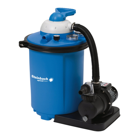
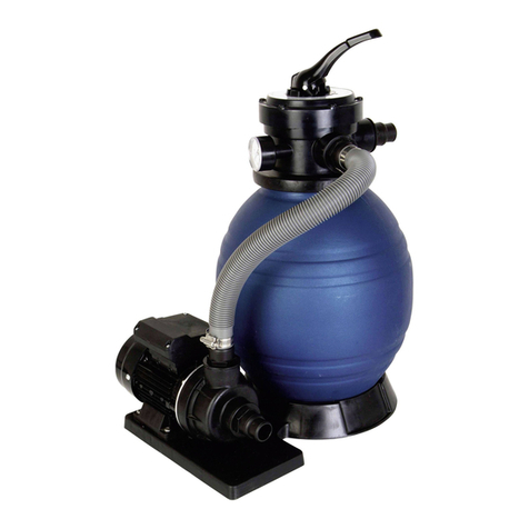
Steinbach Classic 250N Active Balls+ User manual

Originalbetriebsanleitung / Original owner's manual / Notice originale / Istruzioni originali / Manual original / Původní
návod k používání / Eredeti használati utasítás / Izvirna navodila / Pôvodný návod na použitie / Instrukcja oryginalna /
Instrucțiuni originale / Originalne upute / Оригинална инструкция / Orijinal kullanım talimatları
Filteranlage
Classic 250N
Active Balls+
de
Filteranlage......................................................... 5
fr
Système de filtration.........................................54
es
Instalación de filtrado....................................105
hu
Szűrő berendezés..........................................155
sk
Filtračné zariadenie.......................................205
ro
Instalație de filtrare........................................ 255
bg
Филтърна система.......................................305
en
Filter system.......................................................30
it
Impianto filtro................................................... 80
cs
Filtrační zařízení..............................................131
sl
Filtrska naprava..............................................180
pl
Urządzenie filtrujące..................................... 230
hr
Sustav filtriranja..............................................280
tr
Filtre sistemi.....................................................332

XXX
5
7
10
XXX
1
4
8
6
3
9
11
12
13
15
14
2
16
2

A
22
20
21
19
B
22
21
20
19
3

Package contents/components
1
Valve head
2
Filter vessel
3
Pump
4
Vessel seal
5
Locking ring
6
Screen
7
Centering device
8
Drainage screws set
9
Base plate
10
Screw set for fastening the pump (2x)
11
Pressure hose
12
Hose clamp (2x)
13
Manometer
14
Allen wrench
15
Teon tape
16
Filter balls (only with the Acve Balls+ model)
Operang instrucons (without illustraon)
Operating elements
17
Drainage opening
18
Bleeder screw
19
Sucon line
20
Pressure line "PUMP"
21
Return line "RETURN"
22
Backwash line "WASTE"
23
Valve lever
Required tools not included in the package
24
Phillips screwdriver PH1
24
25
Spirit level
25
Optionally available accessories
26
Return line adapter INTEX
Pools/Speed Clean;
art. 040934
29

Contents
Overview.......................................................................................................................2
Package contents/components....................................................................................29
General Informaon.................................................................................................... 31
Read and keep the operang instrucons....................................................................31
Intended use.................................................................................................................31
Explanaon of Symbols............................................................................................... 31
Safety..........................................................................................................................32
Unpacking and checking the package contents............................................................ 35
Preparaon................................................................................................................. 36
Inial cleaning of the device.........................................................................................36
Choosing the locaon...................................................................................................36
Filter sha.................................................................................................................... 37
Preparing the lter vessel.............................................................................................37
Mounng the pump on the base plate........................................................................ 39
Hose connecons ........................................................................................................ 40
Before First Use........................................................................................................... 41
Check the following before start-up............................................................................. 41
Preparing the lter system........................................................................................... 41
Backushing................................................................................................................. 42
Operaon....................................................................................................................42
Modes...........................................................................................................................42
Filtering me................................................................................................................ 44
Exchanging the lter medium.......................................................................................45
Winter storage..............................................................................................................45
Operaon with oor cleaner........................................................................................ 46
Care instrucons...........................................................................................................46
Cleaning...................................................................................................................... 46
Test............................................................................................................................. 47
Storage........................................................................................................................47
Troubleshoong.......................................................................................................... 48
Technical data..............................................................................................................49
Spare parts..................................................................................................................50
Declaraon of Conformity........................................................................................... 51
Disposal...................................................................................................................... 52
Disposing of the packaging...........................................................................................52
Disposing of used appliances....................................................................................... 52
30

General Information
Read and keep the operating instructions
These operang instrucons are a part of this lter system (in the following
also called "device"). It contains important informaon about start-up and
operaon.
Read the operang instrucons and especially the safety instrucons carefully before
using the device. Non-observance of these operang instrucons can lead to severe
injuries or damage to the device.
The operang instrucons are based on the standards and regulaons in eect in the
European Union. Also observe country-specic direcves and laws abroad.
Keep the operang instrucons for further use. If you pass on the device to a third party,
you must pass on these operang instrucons as well.
Intended use
This device has been designed exclusively for cleaning pool water. It can be used in salt
water as long as the salt content of the water is less than 0.5% (salt electrolysis). It
removes visible dirt and is suited for all standard pools with a hose connecon of Ø 32/38
mm.
The lter medium in the lter tank lters dirt parcles out of the owing water and
serves as permanent dirt and oang debris lter for your pool water. The cleaned water
ows back into the pool via the 7-way valve and the return line.
Use exclusively quartz lter sand that meets the
DIN EN 12904 direcve as lter medium. Alternavely, use Steinbach Filter Balls. Please
refer to the secon "Technical data" for the required quanes.
This product is exclusively intended for private use and not suited for the commercial
sector. Only use the device as described in these operang instrucons. Any other use is
considered inappropriate and may lead to material damage or even injury. The device is
not a toy.
The manufacturer or retailer will not assume any liability for damage caused by
inappropriate or incorrect use.
Explanation of Symbols
The following symbols are used in these operang instrucons, on the device or on the
packaging.
This symbol provides you with useful addional informaon on handling
and use.
31

Products marked with this symbol meet all the applicable Community
regulaons of the European Economic Area.
Never use a sharp knife or other pointed object to open the packaging.
You may damage the contents.
Safety
The following signal words are used in these operang instrucons.
WARNING! This signal symbol/word denotes a hazard with an
average risk level that could lead to death or severe
injury if it is not avoided.
CAUTION! This signal symbol/word denotes a hazard with a low
risk level that could lead to mild or moderate injury if
it is not avoided.
NOTICE! This signal word provides a warning about potenal
material damage.
General safety instructions
WARNING!
Risk of electric shock!
Faulty electric installaon or excess mains voltage can cause an
electric shock.
- Only connect the power cable if the mains voltage of the socket
matches that on the type plate.
- Only connect the power cable to an easily accessible socket so
that you can quickly disconnect it in the case of a fault.
- Only operate the device on a grounded socket secured with at
least 16A.
- The device must be powered via a residual current device with a
rated residual current of at most 30 mA.
- Do not operate the device if it shows visible damage or if the
power cable is defecve.
32

- Do not open the device; leave repairs to an expert. Contact the
service address on the back of the instrucon manual for this
purpose. All liability and warranty claims will be void in the case
of arbitrary repairs, improper connecon or wrong operaon.
- Never touch the power cable with wet hands.
- Never pull the power cable out of the socket by the cable; always
hold it by the plug.
-Never use the power cable as a carrier handle.
- Keep the device and the power cable away from naked ames
and hot surfaces.
- Do not place any objects on the power cable.
- Do not bury the power cable.
-Route the power cable such that no one can trip over it.
- Do not kink the power cable and do not place it over sharp
edges.
- Only use extension lines, if required, that are also suitable for
outdoor use. Using an extension line that is suited for outdoor
use reduces the risk of electric shock.
- Do not use the device during a thunderstorm. Switch it o and
pull the power cable out of the socket.
- Always switch o the device and disconnect it from the power
supply if you are not using the device, when cleaning it or in the
case of a fault.
-Only components that meet the original device data must be
used for repair. There are electric and mechanical components in
this device that are indispensable for hazard protecon.
- Only use spare parts and accessory parts supplied or
recommended by the manufacturer. All warranty claims will be
void when using third-party components.
33

Safety instructions for persons
WARNING!
Danger to children and persons with reduced physical, sensory or
mental capacies (such as parally disabled persons/older persons
with reduced physical and mental capacies) or persons lacking
experience and knowledge (such as older children).
Improper handling of the device can lead to severe injury or damage
to the device.
-Only allow others to access the device aer they have read and
comprehended the enre manual or have been instructed about
the intended use and the associated risks.
- Never let persons with reduced physical, sensory or mental
capacies (such as children or drunk people) or a lack of
experience and knowledge unsupervised near the device.
- Never allow children and persons with limited physical, sensory
or mental capacies or persons lacking the respecve experience
and knowledge to operate the device.
- Do not let children clean or service the device.
- Children are not allowed to play with the device or with the
power cable.
- Install the lter system at a sucient distance to the pool wall so
that it cannot be used as an aid for entering the pool.
WARNING!
Risk of injury through insucient qualicaon!
Insucient experience or skills for handling the required tools and
insucient knowledge of regional or normave regulaons for the
required work can lead to severe injuries or material damage.
- Assign all work whose risks you cannot esmate due to
insucient personal experience to a qualied expert.
34

- Do not operate the device under the inuence of drugs, alcohol
or medicaon or if you are red.
NOTICE!
Improper handling of the device can damage the device.
- Select a locaon for the device that is protected from the
weather.
- Do not let the device run dry (without water).
-Before switching anything on the valve head, turn the lter pump
o.
- Never place the device or parts of it in the pool.
-Do not use the device if there are persons in the water.
Unpacking and checking the package contents
NOTICE!
Careless opening of the packaging, especially with the help of sharp
or pointed objects, may cause damage to the device.
- Open the packaging very carefully.
- Do not penetrate the packaging with sharp or pointed objects.
WARNING!
Packaging materials pose a risk of suocaon!
Catching your head in the packaging foil or swallowing other
packaging materials can cause death. There is a higher risk for
children and mentally challenged persons who cannot esmate the
hazard potenal due to lack of knowledge and experience.
- Prevent children and mentally challenged persons from playing
with the packaging materials.
35

NOTICE!
There is a higher risk of damage to the device if it is stored or
transported without the packaging.
- Do not dispose of the packaging.
- In the case of damage, substute the packaging with an at least
similar box.
Checking the delivery for completeness and damage
1. Open the packaging carefully.
2. Take all parts out of the packaging.
3. Check the completeness of the delivery.
4. Check the delivery for damage.
Preparation
Initial cleaning of the device
1. Remove the packaging materials and all protecve foils if present.
2. Clean all parts of the package content as described in the "Cleaning" secon.
The device has been cleaned and is ready for use.
Choosing the location
The lter system is suciently protected from water penetraon and foreign
objects. We nonetheless recommend choosing a site that is protected from
the weather.
-Posion the lter system between the sucon opening and the injecon nozzle.
-Posion the pump below the pool's water level.
- Ensure sucient distance to the pool wall so that the lter system cannot be used as
an aid for entering the pool.
- Make sure that the maximum distance of 2 meters to the pool is not exceeded.
- Install the lter system on a solid base such as a large concrete pao stone. Use a
spirit level
25
to make sure it is level.
Product dimensions:
36

1
C
B
A
040385
Modell: ABC
250 mm 525 mm 425 mm
040386
Filter shaft
A lter sha is required if the pool is parally or enrely installed in the
ground so you can place the pump of the lter system below the pool's
water level.
- Make sure that the lter sha cannot be ooded and that ambient and rainwater can
drain away easily.
You can do so by installing a gravel layer at the boom of the sha. An oponal
immersion pump with a oat switch that is connected to a canal or drain addionally
protects your lter system from rising water inside the sha.
- Ensure sucient natural venlaon of the sha to prevent condensaon.
- Design the size of the lter sha so that you can carry out work on the lter system.
Preparing the filter vessel
1. Undo the locking ring
5
by turning the
screw counter-clockwise. Use the Allen
wrench
14
for this purpose.
2. Put aside the locking ring and its screws.
3. Mount the drainage screws set
8
on the
drainage opening
17
.
2
37

4. Insert the screen
6
in the lter vessel
2
.
5. Posion the screen in the center of the
lter vessel boom.
6. Fill the lter vessel
2
approximately 1/3
with water.
7. Aach the centering device
7
to the
opening of the lter vessel so that it
centers the pipe of the screen.
8. Fill the lter vessel with quartz lter sand
or lter balls
16
.
Please refer to the secon "Technical
data" for the required quanes.
9. Remove the centering device from the
opening of the lter vessel.
Store the centering device for the next
lling.
10. Guide the vessel seal
4
over the boom
of the valve head
1
.
11. Place the valve head on the lter vessel.
12. Align the valve head so that the "PUMP"
connecon points towards the future
posion of the pump (see illustraon in
the secon "Mounng the pump on the
base plate").
3
4
5
6
38

13. Place the locking ring
5
around the valve
head and lter vessel connecng point.
14.
Insert the screws of the locking ring and ghten them clockwise.
15. Remove the bleeder screw
18
on the valve
head by turning it counter-clockwise.
16. Wrap the manometer thread
13
with
Teon tape
15
.
17. Screw in the manometer at the removal
posion of the bleeder screw by turning it
clockwise.
The lter vessel is prepared.
Mounting the pump on the base plate
1. Insert the threaded screws of the screw
set for fastening the pump
10
from below
into the two hexagonal holes in the base
plate
9
.
2. Place the pump
3
on the base plate
9
so
that the threads protrude through the
fastening opening in the pump base.
3. Push the washer and then the serrated
lock washer over the screw thread.
7
8
9
10
XXX
XXX
11
39

4. Put on one winged screw each and ghten it.
The pump is mounted on the base plate.
5. Connect the base plate
9
to the lter vessel
2
.
The base plate is connected to the lter vessel.
Hose connections
- Fasten all aached hose connecons with hose clamps to ensure that the system
does not leak.
We recommend addionally sealing the hose connecons with Teon tape
15
.
- Use suitable pool hoses for the described connecons.
Some hoses, such as the pressure hose, are very s. Place them in the sun
before use so that the heat makes them more exible.
Connecting the return line
You can use hoses with diameters of 32 or 38 mm or an INTEX Pools/Speed
Clean
26
return line adapter.
1. Press and hold down the valve lever
23
on the valve head
1
.
2. Set the valve lever to the "CLOSED" posion and release it.
3. Connect one end of the hose to the "RETURN" connecon on the valve head
1
.
-Aach a hose with a 32 mm diameter to the "RETURN" connecon and fasten it with
a hose clamp.
- Screw the INTEX Pools/Speed Clean
26
return line adapter clockwise onto the return
line
21
on the valve head
1
.
- Slide a hose with a 38 mm diameter over the thread up to the stop of the "RETURN"
connecon and fasten it with a hose clamp.
4. Connect the second end to the connecon on the injecon nozzle of the pool.
The return line
21
is connected.
Connecting the pressure line
1. Aach one end of the pressure hose
11
to the top pump connecon
3
.
2. Place a hose clamp
12
over the pressure hose. Using a Phillips screwdriver PH1
24
,
turn the screw on the hose clamp clockwise to ghten the hose clamp over the
connecon.
3. Place the second hose clamp over the pressure hose.
4. Aach the end of the pressure hose to the "PUMP" connecon on the valve head
1
.
40

5. Posion the hose clamp on the connecon and ghten this one as well with a Phillips
screwdriver.
The pressure line
3
is connected.
Connecting the suction line
You can use hoses with diameters of 32 or 38 mm.
1. Connect the sucon line hose
19
with the front pump connecon.
The sucon line is connected.
Connecting the backwash line
A rubber stopper is inserted in the "WASTE" connecon at the factory. You
can leave this stopper in, if you are not using the backwash line (e.g. when
using lter balls as lter medium), to protect the device from dirt and insects
entering the system.
1. Pull the rubber stopper out of the "WASTE" connecon in the valve head
1
.
2. Connect one end of the hose to the "WASTE" connecon.
3. Guide the second hose end towards the channel connecon.
The backwash line
22
is connected.
Before First Use
Check the following before start-up
1. Make sure that the pump's power cable is disconnected from the power supply.
2. Make sure that the device is located outside the pool and below the water level.
3. Make sure that all feed and drain lines are correctly connected and fastened in place.
4. Make sure that the pool's water level is at least 2.5 to 5 cm above the opening of the
sucon line. If this is not the case, top up the pool.
5. Remove the stopper on the sucon line if applicable.
6. Open the shut-o valve on the sucon line.
The lter system lls automacally with water because it is below the water level.
Preparing the filter system
1. Press and hold down the valve lever
23
on the valve head
1
.
2. Set the valve lever to the "BACKWASH" posion and release it.
3. Allow the lter vessel
2
to ll with water unl the water runs out of the "WASTE"
backwash line
22
.
41

4. Check the lter system and the connecons for leaks.
In the case of leaks, wrap extra Teon tape
15
around the aected connecons.
5. Backwash the system (see secon "Backwashing").
Backflushing
Do not backwash when using Steinbach Filter Balls. If the lter throughput
decreases, we recommend washing the lter balls by hand. If necessary,
exchange the lter balls.
1. Switch the pump
3
o by pulling the power plug.
2. Connect the backwash line (see secon "Connecng the backwash line").
3. Press and hold down the valve lever
23
on the valve head
1
.
4. Set the valve lever to the "BACKWASH" posion and release it.
5. Connect the pump's power plug to the power supply.
6. Backwash the system unl clean water emerges from the backwash line (max. 2
minutes).
7. Switch the pump
3
o by pulling the power plug.
8. Press and hold down the valve lever
23
on the valve head
1
.
9. Set the valve lever to the "RINSE" posion and release it.
10. Connect the pump's power plug to the power supply.
11. Let the pump run for 20 to 30 seconds to remove any residue in the valve head.
12. Switch the pump
3
o by pulling the power plug.
The backwashing is completed.
Operation
CAUTION!
Risk of injury!
A damaged device or damaged accessories may cause injuries.
- Check the device and the accessories (see secon "Tesng").
Modes
To set the modes listed below, proceed as follows:
42

1. Switch the pump
3
o by pulling the
power plug.
2. Press and hold down the valve lever
23
on
the valve head
1
.
3. Turn the valve lever to the desired
posion and let go.
The desired mode is set.
FILTER
- Use this mode as the basic seng of your lter system.
The sucked-in pool water ows into the lter vessel through the top and ows through
the lter medium. Dirt is ltered out in the process and the water is returned to the pool
aerwards.
BACKWASH
Do not backwash when using Steinbach Filter Balls. If the lter throughput decreases,
we recommend washing the lter balls by hand. If necessary, exchange the lter balls.
- Let the pump run in this mode for at most 2 minutes if starng it up for the rst me
or if new quartz lter sand was lled in, or if the manometer shows 0.3 to 0.6 bar
above the normal operang pressure to clean the lter and the quartz lter sand.
The water is guided into the boom part of the lter vessel and ows through the enre
lter. Collected dirt is detached and ushed out via the backwash line.
RINSE
- Let the pump run for 20 to 30 seconds in this mode right aer backwashing, relling
the quartz lter sand or aer inial start-up.
The water is guided into the top part of the lter vessel and the valve head is rinsed. The
water drains via the dirt line. The valve head is cleaned this way.
RECIRCULATE
- Run this mode aer treang the water with chemicals.
The water is guided directly from the valve head to the pool without owing through the
lter. The lter medium does not come into contact with the applied chemicals this way.
12
43

CLOSED
NOTICE!
Risk of damage!
- Never switch on the pump in this mode!
- Use this mode to clean the prelter (if available) or checking the system for leaks and
sealing the aected spots.
The water ow in the pump and in the lter is blocked. Make sure that feed and drain
hoses are lled with water and might have to be closed o with shut-o valves or plugs.
WASTE
NOTICE!
Risk of damage!
- The pool can only be drained up to the minimum water level at
the height of the sucon line. Make sure to switch the pump o
once this level is reached to prevent the pump from running dry.
- Use this mode to clean the pool in the case of heavy soiling.
The water is guided past the lter and discharged directly via the backwash line.
WINTER
NOTICE!
Risk of damage!
-Never switch on the pump in this mode!
- Use this mode to store the lter system in the winter.
The valve lever is in an intermediate posion which relieves the inner valve components.
Filtering time
The pool's water content should be turned over at least three to ve mes in 24 hours
depending on the use and the size of the system. The operang me depends on the
output of the lter system and the pool size.
44

Exchanging the filter medium
The applied lter medium (quartz lter sand or Steinbach Filter Balls) should
be exchanged every 2 to 3 years, depending on the operang period and the
degree of soiling of the device.
1. Switch the pump
3
o by pulling the power plug.
2. Close the shut-o valves or block the water ow to the pool's connecng hoses.
3. Open the screw cap on the drainage opening
17
by twisng it counter-clockwise.
4. Completely drain the water from the lter vessel
2
via the drainage opening.
5. Place the screw cap on the drainage opening and screw it down by turning it counter-
clockwise.
6. Undo the locking ring
5
by turning the screw counter-clockwise. Use the Allen
wrench
14
for this purpose.
7. Put aside the locking ring and its screws.
8. Slowly turn the lter vessel on its head and remove the quartz lter sand or the lter
balls.
9. Remove the screen
6
.
10. Thoroughly rinse the screen under owing water.
11. Rinse the lter vessel with plain water.
12. Carry out steps 4 to 12 as described in the "Preparing the lter vessel" secon.
The lter medium is exchanged.
Winter storage
1. Switch the pump
3
o by pulling the power plug.
2. Close the shut-o valves or block the water ow to the pool's connecng hoses.
3. Uninstall the connecng lines to the pool and drain the hoses.
4. Li the pump and drain it via the two connecons.
5. Remove the lter medium. To do so, carry out steps 3 to 11 in the "Exchanging the
lter medium" secon.
If you are using lter balls, wash these by hand and let them dry completely.
6. Rinse the lter system with tap water.
7. Let the lter system dry completely.
8. Press and hold down the valve lever
23
on the valve head
1
.
9. Turn the valve lever to the "WINTER" posion and let go.
The device can be stored over the winter.
45
Other manuals for Classic 250N Active Balls+
1
This manual suits for next models
2
Table of contents
Other Steinbach Swimming Pool Filter manuals
Popular Swimming Pool Filter manuals by other brands

Oase
Oase SwimSkim operating instructions

Deltec
Deltec MCX 300 Operating instruction

ChlorKing
ChlorKing NEXGEN20 Installation, operation and maintenance manual

poolstar
poolstar POOLEX Sel-in 20 user guide

TIP
TIP Sweeper 18000 3D Translation of original operating instructions

JNS Aquaria
JNS Aquaria ConeS CO Series quick start guide