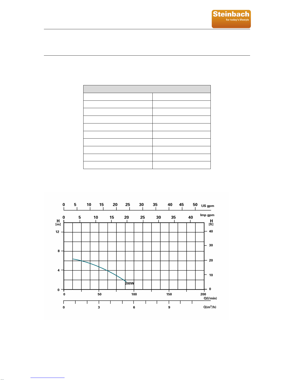
Steinbach Speedclean Eco 30 User manual

Speedclean Eco 30
2011_V1 page 1 of 16
Owner’s Manual
Speedclean Eco 30
Universal Pool Filter System
Art. Nr. 00-40250

Speedclean Eco 30
2011_V1 page 2 of 16
Basic safety precautions should always be followed, including the following: Failure to follow instructions can
cause severe and/or fatal injury.
In this manual, the callout boxes, CAUTION, IMPORTANT and ADVICE have the following meanings:
This heading is used when injury or accidents may occur if the operating instructions, work instructions, work pro-
cedures, etc. are either NOT strictly adhered to, or not carried out all.
This heading is used when damage to the device may occur if the operating instructions, work instructions, work
procedures, etc. are either NOT strictly adhered to, or not carried out all.
This heading is used to call attention to special details or information.
ADVICE
IMPORTANT
CAUTION

Speedclean Eco 30
2011_V1 page 3 of 16
Table of Contents:
1Safety Warnings............................................................................................................................................... 4
2General Information......................................................................................................................................... 5
2.1How Sand Filtration Works ..................................................................................................................... 5
2.2Powering the Filter Pump ....................................................................................................................... 5
2.3Change Valve Positions.......................................................................................................................... 5
2.4Sand and Initial Preparation ................................................................................................................... 5
2.5Safety Notes ........................................................................................................................................... 6
2.6Damage during Delivery ......................................................................................................................... 6
2.7Implied Warranty .................................................................................................................................... 6
2.8Result Damages ..................................................................................................................................... 6
3Technical Specifications................................................................................................................................. 7
4Parts List / Reference...................................................................................................................................... 8
5Installation Instructions .................................................................................................................................. 8
5.1Unpacking Your Filter System ................................................................................................................ 8
5.2Tools & Equipment Required.................................................................................................................. 8
5.3Installation Diagram ................................................................................................................................ 9
5.4Power Source Instructions.................................................................................................................... 10
5.5Setting up the filtration system.............................................................................................................. 10
6Filter Operations............................................................................................................................................ 12
6.1Operation of the 3-way Valve ............................................................................................................... 13
6.2Filtration Time....................................................................................................................................... 13
6.3Filtration................................................................................................................................................ 13
6.4Start Up ................................................................................................................................................ 13
6.5Backwash Process ............................................................................................................................... 14
6.6Cleaning the Filter................................................................................................................................. 15
7Maintenance................................................................................................................................................... 15
7.1To Winterize the System....................................................................................................................... 15
8Troubleshooting............................................................................................................................................. 16
9Service Processing........................................................................................................................................ 16

Speedclean Eco 30
2011_V1 page 4 of 16
1 Safety Warnings
Read all warnings and cautions noted below. Failure to do so could result in serious or fatal injury.
Prior to installation of this unit, carefully read and adhere to all CAUTION, IMPORTANT, and ADVICE
notices located throughout this manual. Failure to comply with these instructions can cause serious in-
jury, death, or damage to the unit.
Risk of suction entrapment hazard, which, if not avoided can result in serious injury or death. Do not
block pump suction at the pump or in the pool as this can cause severe injury or death.
Electrical wiring must be installed by a trained professional and adhere to local code and regulations.
Avoid electric shock. Do not use power extension cords.
Connect only to a Ground-Fault Circuit Interrupter (GFCI) power outlet. Consult a Qualified professional
electrician for safe and proper installation of a qualified electrical outlet.
Incorrectly installed equipment may fail, causing severe injuries or damage to the pump-filter system.
Never submerge the filter and/or pump in water.
Never place the pump or filter in your pool.
Trapped air in the pump-filter system may cause the tank cover to be blown off which can result in death,
serious injury, or damage to the pump-filter system. Ensure all air is out of system before operating.
Never change the 3-way control valve while the system is operating.
Always unplug the system before changing the control valve.
Install this product with a sufficient safety margin from the pool to prevent children from using the system
to access the pool.
Never plug or unplug this unit from an electrical source while standing in water.
Never service this unit with the electrical power cord connected.
Do not operate the system while the pool is being used.
Keep children away from all electrical equipment.
Never allow children to operate this equipment.
The Pool Owner should always exercise caution and common sense when utilizing their swimming pool
and operating equipment.
These caution warnings are not intended to incorporate
all possible instances for risk and/or severe injury.

Speedclean Eco 30
2011_V1 page 5 of 16
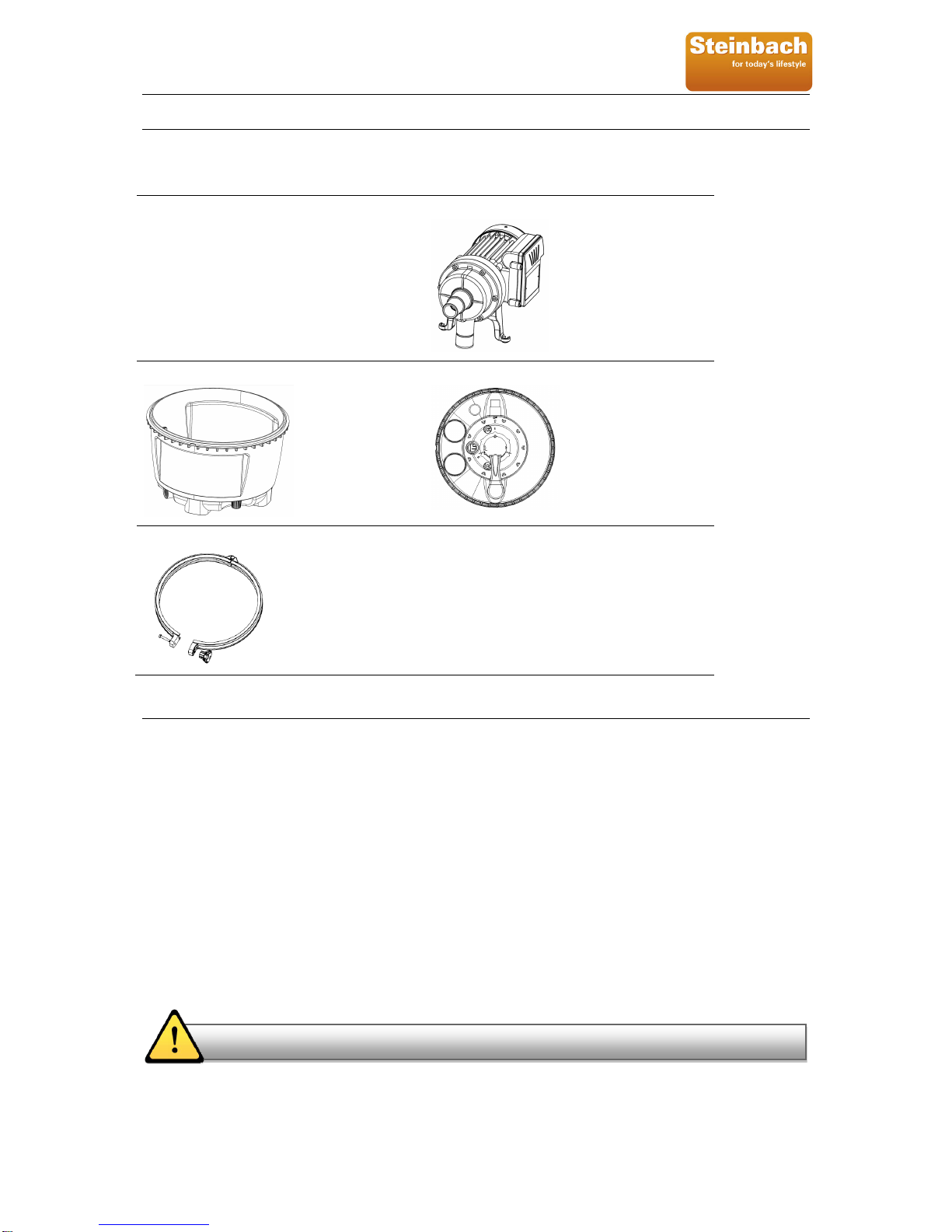
2 General Information
This manual provides information relating to the installation, utilization and maintenance of our filtration system.
We recommend that you read this manual in its entirety and keep it for future reference.
The filter included in the filtration system consists of high-grade Polypropylen (PP). It is seamless and manufac-
tured as a single unit and it is absolutely corrosion resistant and resistant to commercially available swimming
pool chemicals. (Prerequisite: Compliance with the standard recommended specifications for the pH- and chlo-
rine-value). It is equipped with a container drainage system, pressure gauge, built-in container components, e.g.
bottom strainer for even water distribution and a stable separation wall between the filter and the fresh water
chamber. The filter container comes ready to plug-in and is supplied with a user-friendly 3 Position Multi-Port
Valve integrated into the tank cover and an approved filter pump. The system will be delivered as a plug-in con-
struction set for final assembly on location.
Read this manual carefully before installation. The filtration system and pump must be installed in accordance
with the standards in effect.
We decline all responsibility for the consequences of failure to comply with the installation instructions. We rec-
ommend that you comply with the power source instructions to avoid overloading the pump motor and/or electric
shock.
This filtration system is not intended for use by persons with reduced physical, sensory or mental capabilities, or
lack of experience and knowledge.
Safety notes and callout boxes should always be observed.
2.1 How Sand Filtration Works
The Universal Pool Filter System is designed to use special quartz sand to remove dirt particles from pool water.
Filter sand is loaded into the filter tank and functions as a permanent dirt and debris removing media. Pool water,
which contains dirt particles, is pumped through the intake hose leading from the pool through the filter pump to
the filter tank and is directed by the filter control valve to the top of the filter tank. As water is pumped through the
filter sand, dirt particles are trapped by the bed of sand and filtered out. The cleaned/filtered water is then returned
from the bottom of the filter tank, through the control valve and back to the pool through the return hose. This se-
quence is continuous and automatic and provides total recirculation of pool water through your filter and hose
connections. After a period of time, the accumulated dirt in the filter causes a resistance to the flow of water and
an increase in pump pressure. When this happens, it is time to clean (backwash) the filter. To backwash the sys-
tem, you must change the valve to the backwash position. When in backwash mode, the water flow is automati-
cally reversed through the filter so that it is direct to the bottom of the tank, up through the sand, which flushes
any trapped dirt and debris out through the waste line. After backwashing, the filter valve should be changed back
to the filtration position to resume normal filtering.
NOTE: Never change valve positions while the pump is running!
2.2 Powering the Filter Pump
It should be noted that the sand filter system you have purchased does not have an on/off switch. Rather, power
to the filter pump is connected and disconnected by means of plugging in and unplugging the power cord from the
power source. It is important that you read and follow the instructions on proper power supply sources.
2.3 Change Valve Positions
It is very important to have the sand filter pump off, whenever a valve change is made. In other words, the pump
should not be running when you change valve settings (i.e. moving from Filtration position to the Backwash posi-
tion). Changing valve positions while the pump is running could result in irreparable damage to the valve and its
inner workings.
2.4 Sand and Initial Preparation
The filter system you have purchased requires a specific type of sand (not included) for optimum operation:
namely, Quartz Sand, double burned, with a particle size of 0.40 - 0.80mm.You can purchase this sand at most
pool supply stores. While the sand will come packaged, it is important that the sand be cleaned prior to running
the filter system in filtration mode. Failing to pre-clean the sand will result in tiny and dusty sand sediment in your
pool which can be difficult to remove. Therefore, please read and follow the instructions for cleaning the sand in
the initial set up section provided in this manual.

Speedclean Eco 30
2011_V1 page 6 of 16
2.5 Safety Notes
Your filter pump was constructed and tested and left the manufacturing plant in technically operational condition.
In order to maintain this condition and ensure safe operation, the user should observe the notes and product in-
formation contained in this technical handbook. If there is any indication that safe operation is no longer possible,
the device is to be disconnected from the power supply and secured against accidental use.
This is the case when:
The device has visible damage
The device no longer appears functional
After long periods of storage in poor conditions
2.6 Damage during Delivery
Your filter system has been carefully and professionally packed for delivery. Please check to ensure that the
package is undamaged and that all parts are in the box. If you purchased this product on order and the product
was shipped to you, ensure that delivery is complete. Damage to product as a result of shipping is not the re-
sponsibility of the supplier and must be immediately reported to the shipper. The shipper assumes the liability for
damages during delivery, the supplier is not responsible for it.
2.7 Implied Warranty
The manufacturer warranties safe operation and reliability only under the following conditions:
The filter system is installed and operated according to the assembly and operating instructions.
Only original replacement parts are used. (consumable parts do not fall under the warranty)
Expendable parts do not fall under the warranty. These include:
All O-rings
Pressure gauge
Mechanical seal, complete
2.8 Result Damages
We cannot be responsible for damages to the product if the product is not used in accordance with the instruc-
tions provided.
Before loosening any threaded connections on the filtration system, be sure that the suction and pressure hoses
are closed to prevent water flow over the motor. Damages caused by flooding the pump are not covered under
the warranty. Before starting work, you must first pull out the plug respectively take off the power of the system.
IMPORTANT

Speedclean Eco 30
2011_V1 page 7 of 16
3 Technical Specifications
Sand filter system (400 mm filter housing diameter), with pump, multi-port valve, pressure gauge, special filter
screen insert, quick-close latch. UV desinfection system compatible.
Speedclean Eco 30
Flow Volume (Q) 3,8 m³/h
Operating Pressure 0,4 bar
Rated Voltage 230V 1N~ AC 50Hz
Power 200 Watt
Protection Class IP X5
Cable length including plug 1,5 m
Max. ambient temperature 35 °C
Sand Volume approx. 12 kg
Dimensions (LxWxH) 400x400x470mm
Weight (without filling) approx. 12 kg
Performance chart Speedclean Eco 30

Speedclean Eco 30
2011_V1 page 8 of 16
4 Parts List / Reference
Before starting installation, check to make sure all parts are present in package.
Primary Components
Pump Adapter 32/38mm (1) Water Pump (1)
See attached Parts-List
Filter Tank (1) Tank Cover with Control-Valve (1)
Tension Ring (1) Filter Pump mounting screws (1)
See attached Parts-List
5 Installation Instructions
5.1 Unpacking Your Filter System
Carefully remove the product and all component parts from the box. Cross reference all parts in the box with the
parts list reference chart to make certain all parts are present before beginning assembly.
5.2 Tools & Equipment Required
The following items are not included with your new filter system, but will be required for proper installation and
operation:
#2 Screwdriver
Quartz Sand with a particle size of 0.40 - 0.80mm in accordance with DIN EN 12904 (approx. 12 kg).
A small container of Vaseline.
G.F.C.I. (Ground Fault Circuit Interrupter)
An absolutely level 0.60 x 0.60 m surface made of filter gravel (crushed rock) or compressed concrete with
an open drainage attachment or drainage ditch for backwash water is necessary.
Proper installation, operation and maintenance of your filtration system are the best guarantees of good filtration
quality and a long service life. We recommend that you take note of the information presented in this handbook.
We are not liable for damages caused by non-professional electrical installation, or electrical installation not in ac-
cordance with instructions.
ADVICE

Speedclean Eco 30
2011_V1 page 9 of 16
5.3 Installation Diagram
The following illustration shows the components of the filter system.
1) Filter Container
2) Recirculation Pump Speed
3) 3-Way Central Valve
4) Suction-side connection from pool (untreated water)
5) Pressure side connection to pool (purified water)
6) drainage line (slurry) - downstream of the 3-way central valve to discharge installed side
7) Clamp Ring
8) Pressure Gauge
9) 2 ¼” opening for UV pipes and/or 3 KW heating element
10) Drain vor filter vessel
Know where you will be placing the filter once you have it assembled? The area you select needs to be a hard
level surface (see above) that will also position the filter to be lower than the pool’s water level and with a suffi-
cient safety margin from the edge of the pool. The filter pump must be installed below the water level so that wa-
ter will naturally flow towards it. This puts less strain on the pump and can improve service life. If the suction line
is kept short, pump suction time will be reduced and the pump capacity will be increased
The following instructions are based on the assumption that your above-ground pool is assembled, filled with wa-
ter, and that your pool is equipped with the necessary filtration hoses needed to operate with a filter (cartridge or
otherwise). If your pool is not assembled, please refer to the pool’s installation manual for details. If you do not
have hoses for your pool’s intake and return, you will need to purchase the hoses from a pool supply store.
CAUTION
ADVICE
1
2
3
4
5
6
7
8
9
10

Speedclean Eco 30
2011_V1 page 10 of 16
5.4 Power Source Instructions
The filter pump system you have purchase is equipped with a standard electrical cord and plug which should only
be connected to a power outlet protected by a qualified Ground –Fault-Circuit-Interrupter (GFCI) with IΔN≤30mA
that has been installed by a professional electrician and adheres to local codes and regulations. Electrical installa-
tions should be carried out, taking the safety zone into consideration, by a locally licensed electrician to the rele-
vant national specifications for swimming pool construction (in Austria, EN1, part 4, §49; in Germany, DIN 57100,
Part 702 and VDE 0100, Part 702. To avoid electric shock, power cord extensions should not be used.
5.5 Setting up the filtration system
1. Filter Pump Assembly Instructions
a) The filter pump is screwed onto the cover of the filter system. Un-
screw the two screws (1) on the top of the cover:
b) Place the pump on the cover and secure it to the top of the cover
with the screws on both sides.
c) The front part of the pump should then be fastened (pointing vertical-
ly downwards) onto the cover at the pump nozzle, using the nut (2).
Ensure that the nut is properly tightened.
2. Filling the filter material
a) Release the screw on the clamp ring and remove the ring by lifting it upwards. Next raise the cover with
the O-ring (circumferential sealing cord). Once this has been completed, check to ensure that the bottom
strainer is correctly positioned and that the separation wall for the purified water chamber is seated
properly. In doing so, please note that the guide tracks on the bottom strainer grating are a continuation
of the side-mounted guide tracks on the container wall. The separation wall has to be slid onto these
tracks with by the side-mounted positioning hooks on its upper edge so that the upper edge of the wall
abuts with the upper container edge:
To prevent damage to the container and the bottom strainer, the container should be filled with 20 cm of water be-
fore adding the filter sand.
IMPORTANT
CAUTION
1
Intake from the
Sand Chamber
Filtered Water Chambe
r
Sand Chamber
Filter Bottom Straine
r
Separation Wall between the
Filtered Water Chamber and
the Sand Chamber
Container drain below
the bottom strainer
2

Speedclean Eco 30
2011_V1 page 11 of 16
b) After that, fill the filter material in the sand chamber. The filter material consists of double-burned
quartz sand that has to be ordered separately. The quartz sand must have a grain size of 0.40
mm to 0.80 mm be in accordance with DIN EN 12904.
c) Carefully re-seal the container. The receiving surface of the sealing ring (O-ring) as well as the
O-ring itself should be cleansed of all sand and dirt and lightly greased with Vaseline. Ensure
that the seal is seated properly. Place the filter cover on the rear container edge, such that the
pump connection (grey hose nipple Ø38mm, in the 3-way central valve from the pump) faces
forward. Guide the securing lug on the cover (between the two openings) into the central secur-
ing latch in the clean water chamber, ensuring that the cover mounts close evenly and uniform-
ly. Slide the clamp ring over the container and cover bead, and screw it in position.
It is important to ensure that sand does not exceed the recommended quantity/weight and that no sand is permit-
ted to enter the filtered water chamber, as this can cause deposits in the swimming pool.
1. Hooking up the filtration system
The connection to the pool is made by a flexible hose. To connect to the pool, one end of a flexible hose is at-
tached to the suction side of the filter pump and the other to the pool (skimmer). The purified water return is con-
nected by running a flexible hose from the right connection of the filter container cover ("to pool") to the pool inlet.
A third hose is connected to the filtration system ("to drain") and the other end to the base drain or to open DN
100 drainage channel. All three hoses are then slipped over the corresponding hose grommets on the container
cover and fixed in place with a hose clamp (not supplied). For convenience of operation, ball cocks may be in-
stalled poolside between the skimmer, the pool intake and the corresponding hose grommets.
Possible installation configuration
Filter system to Pool (pressure side) Spiral Hose Ø32/38 mm
Pool to Filter system (suction side) Spiral Hose Ø32/38 mm
Ensure that all hose connections are tight and that the hoses are not kinked or bent at severe angles.
Do not power pump at this point.
IMPORTANT
ADVICE
ADVICE

Speedclean Eco 30
2011_V1 page 12 of 16
6 Filter Operations
The filtration system is equipped with a 3-way central valve on the container cover for manual control of the de-
vice, which is designed for the required flow rate. Press down firmly on the valve lever with the heels of your
hands then rotate to the desired setting. Before moving on to the Startup Section, please make yourself familiar
with your new filtering system’s valve settings and functions.
Setting Complete Water Flow/Function
V
alve Diagram
Filtration
Position 1
Function: Vacuum, regular pool filter action. This
is the setting the filter will be set to most of the
time. In this position, water is directed through the
top of the filter where it compresses and flattens
down the sand. Contaminants are trapped by the
sand as water makes it way to the bottom strain-
er, out of the filter and back to the pool.
Backwash
Position 2
Function: Clean filter of captured debris. This is
the position needed to clean the filter and sand.
You’ll know it is time to backwash when the pres-
sure gauge rises 0,3 to 0,6 bar above what it
normally reads when the filter is clean. In this po-
sition, water is directed through the bottom
strainer, reversing the flow through the tank. This
causes the sand to separate and lift while releas-
ing trapped debris out the waste line.
Closed
Position 3
Function: This position stops the flow of water in-
to the pump and filter.
CAUTION: Do not run pump with valve in this
position.

Speedclean Eco 30
2011_V1 page 13 of 16
Do:
Be aware and make note of the filter pressure when the sand is clean. Backwash when you see an
increase of 0.3 to 0.6 bar on the pressure gauge.
Backwash long enough to get the job done right. Let the system backwash until the water exiting the
waste line is clear. Note that backwashing can remove 200 to 1100 liters of water from your pool so pay
attention. Also, be aware of local codes regarding pool water disposal as some communities outlaw drai-
nage.
Protect bottom strainer while replacing or adding sand. Fill the tank with approx. 20cm of water and co-
ver the water chamber to avoid getting sand inside.
Don‘t:
Move valve handle while the pump is running. It will damage the valve and possibly other equipment as
well.
Backwash excessively. Sand filters operate more efficiently during mid-cycle. Some level of debris in
the sand bed actually helps filtration and makes the filter more effective. Too much backwashing will
reduce efficiency.
Vacuum the pool in backwash mode. You can plug up the strainer at the bottom of the filter which will
result in inefficient operation. Plus you may have to remove all of the sand to get it unclogged.
6.1 Operation of the 3-way Valve
The 3-way Valve is designed to give the required flow rate for each action that is described above. Always make
sure the power source to the filter is unplugged before changing valve positions. To change valve positions, press
down firmly on the valve lever and rotate to the desired setting.
6.2 Filtration Time
The water contained in the swimming pool should be circulated through the pump at least 3-5 times in a 24-hour
period, depending on the load on the system and its size. The time required depends on the capacity of the filtra-
tion system and the size of the swimming pool. We recommend a minimum operating time of 12 hours per day. If
the pool is used intensively or the water is unusually dirty, the operating time should be increased. Using a simple,
commercially available mechanical timer or filter controls, the filtration times can be programmed in advance at
various intervals.
6.3 Filtration
The polluting agents from the re-circulated water are retained in the filter bed in the filter container. Adding proper
flocculants by hand improves filtration considerably and reduces the need for treating agents. In addition to the
mechanical effects of the filter, so-called physiochemical processes performed by the flocculent in the filter bed
also play a role in the purification capacity of your filtration system.
Never use the valve lever as a handle to carry or lift the filter.
6.4 Start Up
Once the filter system has been properly assembled, the sand chamber filled with sand and the hoses connected
as described above, you may begin with filtration. However, we recommend that you clean and prepare the new
sand that is in the sand chamber first. Cleaning the sand prior to filtering your pool will remove most of the dust
and tiny sand particles that may exist in the sand. If you move straight to filtering, these particles will end up in
your pool. To clean the sand, please follow the instructions below.
CAUTION
IMPORTANT DO & DONT‘S

Speedclean Eco 30
2011_V1 page 14 of 16
Do not plug the system in until advised to do so below.
1) Make certain the pump is not plugged in to a power supply.
2) Start with the valve in Closed position (position 3).
3) If you haven’t done so already, fill your pool with water. Regarding the required filling height refer to the
manual of your pool.
4) Release the shut off valve at the intake port in the pool. If you plugged the intake port, remove the plug to
allow the water to flow into the intake hose.
5) With the filter-pump system installed in a location level lower than your pool’s water level – water will au-
tomatically flow into the pump-filter system.
6) Allow the filter tank to fill with water.
7) Check for leaks and make any necessary adjustments.
8) Follow the backwash process on following page.
According to DIN EN 12904 at the used quartz sand, an undersize (minus material) of 10 percent by weight is
permitted. This can cause, that sometimes small amounts of sand appear in the pool, until the washing-out of the
sand has finished.
6.5 Backwash Process
Disconnect the Motor/Pump from the Power Source.
Attach backwash hose (not included) to backwash port.
Place the Multi-Port Valve in the Backwash position (Nr. 2).
Reconnect to power source.
Run filter in backwash mode until discharge water is clear (approx. 5 minutes).
Disconnect the Motor/Pump from the Power Source.
Place the Multi-Port Valve in the Filtration position (Nr. 1).
Reconnect to power source.
Your filtration system is running and ready for further operation.
NOTE: When the filter pump is properly connected to the power supply, the pump will begin to push the water
through the bed of sand and out backwash hose. In this process, water will be drained from your pool as it cleans
the bed of sand within the tank. You may want to put a garden hose in the pool to add water in while the pump is
pulling water out so that the water level does not go below the intake return ports. While the sand is being
cleaned, run your fingers through the water exiting the backwash hose. When you can no longer feel sandy grit in
the water, the sand cleaning process should be complete.
ALWAYS unplug power source to pump before changing valve positions.
ADVICE
CAUTION
IMPORTANT

Speedclean Eco 30
2011_V1 page 15 of 16
6.6 Cleaning the Filter
The constant build-up of dirt increases resistance in the filter. If the pressure (see the pressure gauge) in the filter
container increases by approximately 0.2 – 0.3 bar above the original pressure reading, the filter needs to be
backwashed. Please follow the instructions in the chapter “Backwash Process”.
In order to ensure the hygiene and good operation of the filter, and to optimize the filter capacity, the filter should
be backwashed regardless of operating times and how dirty it is due to increased load (increased pressure) at
least every 8 days. When subject to greater loads it should be backwashed more frequently.
7 Maintenance
The chart below outlines the recommended maintenance schedule for your Sand Filter System.
Intervals Maintenance Items
Weekly Backwashing, regardless of how dirty the filter is.
Annually (only when the filter is located out
of doors)
Winterize the system before the first frost; replace the sand in
the springtime before placing the filter into operation again.
Before loosening any threaded connections on the filtration system, be sure that the intake and return hoses are
closed or plugged to prevent water flow over the motor. Before starting work, you must first pull out the plug re-
spectively take off the power of the system.
The pump must not be operated without a strainer basket or strainer basket handle, as the pump may become
clogged and blocked.
7.1 To Winterize the System
1) Unplug the pump from the power source.
2) Close the shut off valves or block the flow of water at the pool inlet and return ports.
3) Disconnect the filtration system from the pool, drain the tank and hoses.
4) Place the handle on the central valve between two positions to relieve the tension on the spring and in-
ternal valve components.
5) Store the filter system in a location protected from frost and severely cold temperatures. In a garage or
insulated storage shed is recommended.
CAUTION
CAUTION
ADVICE

Speedclean Eco 30
2011_V1 page 16 of 16
8 Troubleshooting
Malfunction Cause Solution
Pressure gauge has reading
over 1 bar.
Dirty filter bed Backwash the Filter (Valve Position
Nr. 2)
Pressure is too low Suction line contaminated with dirt.
Pump gets too little water.
Clean suction line
Air in the pump Poor seal on the suction side Tighten hose clamps and connect-
ing fittings.
Water flows into the drainpipe Dirt around the seal of the Central
Valve
Unscrew the Central Valve from fil-
ter cover and clean the seal
Leaking filter Seal Defective Check the seal, replace if needed
Pump does not run Not plugged in Check the socket and power cord
G.F.C.I/ or main circuit breaker tripped Switch on the breaker (if it is imme-
diately tripped again, there is a de-
fect in pump or controls)
Pump motor defective Replace the entire pump
Filter System is switched-off by a time
switch or a filter control system
Check settings
Sand in Pool If the sand is newly replaced, the un-
dersized grains are still present.
Backwash several times until the
backwash water is clear. (Valve
Position Nr. 2)
Separation wall in filter is im-properly
installed.
Check the separation wall for prop-
er positioning.
Filter bottom strainer is damaged. Replace the filter bottom strainer.
Repairs on the pump should only be performed by trained and qualified, professional technicians.
9 Service Processing
For technical information, missing parts or in the case of a complaint, please contact our customer service:
Important note:
On the pump label of your filter pump is a serial number (B/...) indicated and on the tank cover is a lot
number shown (read from above on handle), please provide this data in the case of a complaint.
Steinbach VertriebsgmbH
Aistingerstrasse 2
4311 Schwertberg
Tel. Austria: (0820) 200 100 100 (0,145€ per minute from all networks)
Tel. Germany: (0180) 5 405 100 100 (0,14€ per minute from landline, mobile radio max. 0,42€ per minute)
e-mail: service@steinbach.at
www.steinbach.at
ADVICE


Lieber Kunde!
Die Anleitung in Ihrer Sprache finden Sie unter www.steinbach.at/manual, sollten Sie keinen Internet Zugang haben, können Sie die Anleitung
schriftlich bei uns anfordern. Wir senden Ihnen diese gerne kostenlos zu.
Dear customer!
Instructions in your language are available at www.steinbach.at/manual. In case you do not have internet access, please write us to request the
instructions. We will be happy to send you a copy without additional cost.
Cher client
Vous trouverez l'instruction dans votre langue sur www.steinbach.at/manual, si vous n'avez pas accès à l' Internet, merci de commander
l'instruction par écrit. Nous vous l'enverrons gratuitement.
Gentile Cliente!
al. Qualora Lei non sia fornito di accesso ad Internet, può chiederci le
istruzioni per iscritto e noi saremo lieti di inviargliele in forma gratuita.
Vam besplatno dostaviti.
Stimate client!
Tisztelt Vásárló!
A használati útmutatót az Ön anyanyelvén megtalálja a www.steinbach.at/manual weboldalon. Amennyiben nincs internet hozzáférési
í
Vam bomo
-
e.
Milý zákazník!
Beste klant!
De instructies in uw taal, zie www.steinbach.at/manual, moet u geen toegang tot internet hebben, kunt u de handleiding schriftelijk aanvragen.
Deze worden gratis aan u verzonden.
Szanowny Kliencie,
a
esplatno.
¡Estimado cliente!
Las intrucciones en su idioma puede encontrarlas en www.steinbach.at/manual, en caso de que no disponga de acceso a internet, puede
solicitárnoslas por escrito. Se las enviaremos gratis con mucho gusto.
Prezado cliente!
Aqmanual
por escrito. Nós teremos o prazer de enviá-lo gratuitamente.
Steinbach VertriebsgmbH, Aistingerstraße 2, 4311 Schwertberg, Austria
Sprachen / Language
Table of contents
Other Steinbach Swimming Pool Filter manuals

Steinbach
Steinbach 040590 User manual

Steinbach
Steinbach S1 User manual

Steinbach
Steinbach Classic 250N Active Balls+ User manual

Steinbach
Steinbach Speedclean Comfort 75 User manual

Steinbach
Steinbach 040590 User manual

Steinbach
Steinbach 079030 User manual

Steinbach
Steinbach Speed Clean Classic 300 User manual
Popular Swimming Pool Filter manuals by other brands

Pentair Pool Products
Pentair Pool Products Warrior owner's manual

Davey
Davey PoolFresh Installation and operating instructions

Pool Technologie
Pool Technologie JUSTSALT UNO Instructions for use

STA-RITE
STA-RITE PRDE40 owner's manual

Pool Technologie
Pool Technologie UNO Instructions for use

Xtreme Power
Xtreme Power 90154 Owner's manual and safety instructions