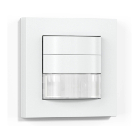
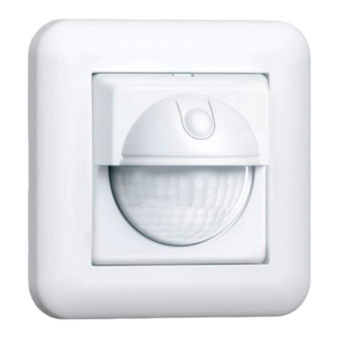
STEINEL IR 180 COM2 Owner's manual

- 3 -
110053679 04/2017_J Technische Änderungen vorbehalten. / Subject to technical modification without notice.
RUS CN BG LV LT EST HR SLO RO PL SK CZ HTR GR NFIN DK S P E I NL FGB D
IR 180 COM1/COM2
HF 180 COM1/COM2
Information
IR 180
HF 180
000000000 07/2013 Technische Änderungen vorbehalten.
STL-6779-16_BDAL_180er SERIE.indd 1 12.05.16 13:04
D STEINEL Vertrieb GmbH · Dieselstraße 80-84
33442 Herzebrock-Clarholz · Tel: +49/5245/448-188
Fax: +49/5245/448-197 · www.steinel.de
A Steinel Austria GmbH · Hirschstettner Strasse 19/A/2/2
A-1220 Wien · Tel.: +43/1/2023470 · Fax: +43/1/2020189
CH PUAG AG · Oberebenestrasse 51 · CH-5620 Bremgarten
Tel.: +41/56/6488888 · Fax: +41/56/6488880 · [email protected]
GB STEINEL U.K. LTD. · 25, Manasty Road · Axis Park
Orton Southgate · GB-Peterborough Cambs PE2 6UP
Tel.: +44/1733/366-700 · Fax: +44/1733/366-701
IRL Socket Tool Company Ltd · Unit 714 Northwest Business
Park · Kilshane Drive · Ballycoolin Dublin 15
Tel.: 00353 1 8809120 · Fax: 00353 1 8612061
F STEINEL FRANCE SAS · ACTICENTRE - CRT 2
Rue des Famards - Bât. M - Lot 3
F-59818 Lesquin Cedex · Tél.: +33/3/20 30 34 00
Fax: +33/3/20 30 34 20 · [email protected]
NL Van Spijk B.V.
Postbus 2 · 5688 HP OIRSCHOT · De Scheper 402
5688 HP OIRSCHOT · Tel. +31 499 571810
Fax. +31 499 575795 · [email protected] · www.vanspijk.nl
B VSA Belgium · Hagelberg 29 · B-2440 Geel
Tel.: +32/14/256050 · Fax: +32/14/256059
[email protected] · www.vsabelgium.be
L Minusines S.A. · 8, rue de Hogenberg
L-1022 Luxembourg · Tél. : (00 352) 49 58 58 1
Fax : (00 352) 49 58 66/67 · www.minusines.lu
E SAET-94 S.L. · C/ Trepadella, n° 10 · Pol. Ind. Castellbisbal
Sud · E-08755 Castellbisbal (Barcelona) · Tel.: +34/93/772 28
49 · Fax: +34/93/772 01 80 · [email protected]
I STEINEL Italia S.r.l. · Largo Donegani 2 · I-20121 Milano
Tel.: +39/02/96457231 · Fax: +39/02/96459295
[email protected] · www.steinel.it
P F.Fonseca S.A
Rua João Francisco do Casal 87/89
Esgueira, 3800-266 Aveiro - Portugal
Tel. +351 234 303 900 · Fax. +351 234 303 910
[email protected] · www.ffonseca.com
S KARL H STRÖM AB · Verktygsvägen 4 · S-55302 Jönköping
Tel.: +46/36/31 42 40 · Fax: +46/36/31 42 49 · www.khs.se
DK Roliba A/S · Hvidkærvej 52 · DK-5250 Odense SV
Tel.: +45 6593 0357 · Fax: +45 6593 2757 · www.roliba.dk
FI Oy Hedtec Ab · Lauttasaarentie 50
FI-00200 Helsinki · Puh.: +358/207 638 000
[email protected] · www.hedtec.fi/valaistus
N Vilan AS · Olaf Helsetsvei 8 · N-0694 Oslo
Tel.: +47/22725000 · [email protected] · www.vilan.no
GR PANOS Lingonis + Sons O. E. · Aristofanous 8 Str.
GR-10554 Athens · Tel.: +30/210/3212021
Fax: +30/210/3218630 · [email protected]
PL „LŁ“ Spółka z ograniczoną odpowiedzialnością sp.k.
Byków, ul. Wrocławska 43 · PL-55-095 Mirków
Tel.: +48 71 3980818 · Fax: +48 71 3980819
CZ ELNAS s.r.o. · Oblekovice 394 · CZ-67181 Znojmo
Tel.: +420/515/220126 · Fax: +420/515/244347
[email protected] · www.elnas.cz
TR SAOS Teknoloji Elektrik Sanayi ve
Ticaret Limited Şirketi
Halil Rıfat Paşa mahallesi
Yüzerhavuz Sokak
PERPA Ticaret Merkezi A Blok
Kat 5 No.313 · Şişli / İSTANBUL
Tel.: +90 212 220 09 20 · Fax: +90 212 220 09 21
[email protected] · www.saosteknoloji.com.tr
H DINOCOOP Kft · Radvány u. 24 · H-1118 Budapest
Tel.: +36/1/3193064 · Fax: +36/1/3193066
LT KVARCAS · Neries krantine 32 · LT-48463, Kaunas
Tel.: +370/37/408030 · Fax: +370/37/408031
EST Fortronic AS · Tööstuse tee 10 · EST-61715, Tõrvandi,
Tartumaa · Tel.: +372/7/475208 · Fax: +372/7/367229
[email protected] · www.fortronic.ee
SLO ELEKTRO – PROJEKT PLUS D.O.O.
Suha pri Predosljah 12 · SLO-4000 Kranj
PE GRENC 2 · 4220 Škofja Loka
Tel.: 00386-4-2521645 · GSM: 00386-40-856555
[email protected] · www.priporocam.si
SK NECO SK, a.s. · Ružová ul. 111 · SK-01901 Ilava
Tel.: +421/42/4 45 67 10 · Fax: +421/42/4 45 67 11
[email protected] · www.neco.sk
RO Steinel Distribution SRL · Parc Industrial Metrom
RO - 500269 Brasov · Str. Carpatilor nr. 60
Tel.: +40(0)268 53 00 00 · Fax: +40(0)268 53 11 11
www.steinel.ro
HR Daljinsko upravljanje d.o.o. · Bedricha Smetane 10
HR-10000 Zagreb · t/ 00385 1 388 66 77
f/ 00385 1 388 02 47 · [email protected]
www.daljinsko-upravljanje.hr
LV Ambergs SIA · Brivibas gatve 195-16 · LV-1039 Riga
Tel.: 00371 67550740 · Fax: 00371 67552850
www.ambergs.lv
BG ТАШЕВ-ГАЛВИНГ ООД
Бул. Климент Охридски № 68 · 1756 София, България
Тел.: +359 2 700 45 45 4 · Факс: +359 2 439 21 12
[email protected] · www.tashev-galving.com
RUS Best - Snab
ул.1812 года, дом 12 · 121127 Москва · Россия
Tel: +7 (495) 280-35-53
[email protected] · www.steinel.su
CN STEINEL China
Representative Office · Shanghai Rm. 25 A,
Huadu Mansion No. 838
Zhangyang Road Shanghai 200122
Tel: +86 21 5820 4486 ·Fax: +86 21 5820 4212
[email protected] · [email protected] · www.steinel.cn
04/2017 SENSOREN Version „K“
110000000 04/2017_K Technische Änderungen vorbehalten. / Subject to technical modification without notice.
DGBCZSKPLROSLOHRESTLTLVRUSBG
中

- 2 - - 3 -
D � � � � � � � � � � 12
GB � � � � � � � � � 23
CZ � � � � � � � � � 34
SK � � � � � � � � � 45
PL � � � � � � � � � 56
RO � � � � � � � � � 67
SLO � � � � � � � � 78
HR � � � � � � � � �89
EST � � � � � � � 100
LT � � � � � � � � � 111
LV� � � � � � � � � 122
RUS � � � � � � � 133
BG � � � � � � � � 144
CH � � � � � � � � 155
Textteil beachten!
Follow written instructions!
Dodržujte písemné pokyny!
Dodržiavajte písomné informácie!
Postępować zgodnie zinstrukcją!
Respectați instrucțiunile următoare!
Upoštevajte besedilo!
Pridržavajte se uputa!
Järgige tekstiosa!
Atsižvelgti į rašytines instrukcijas!
Pievērsiet uzmanību teksta daļai!
Соблюдать текстовую инструкцию!
Прочетете инструкциите!
遵守文字说明要求!
...

- 4 - - 5 -
IR
HF

- 6 - - 7 -
2.
4. II III
,I2.
4. II III
,I2.
4. II III
,I
2.
4. II III
,I
III II
IIII II II
I
III II
I
III I
2.
4. II III
,I2.
4. II III
,I2.
4. II III
,I
2.
4. II III
,I
III II
IIII II II
I
III II
I
III I

- 8 - - 9 -
2.
4. II III
,I2.
4. II III
,I2.
4. II III
,I
2.
4. II III
,I
III II
IIII II II
I
III II
I
III I

- 10 - - 11 -

- 12 - - 13 -
D
1. Zu diesem Dokument
Bitte sorgfältig lesen und aufbewahren!
–Urheberrechtlich geschützt. Nachdruck, auch auszugsweise, nur mit
unserer Genehmigung.
–Änderungen, die dem technischen Fortschritt dienen, vorbehalten.
Symbolerklärung
Warnung vor Gefahren!
Verweis auf Textstellen im Dokument�
2� Allgemeine Sicherheitshinweise
!
Vor allen Arbeiten am Gerät die Spannungszufuhr unterbrechen!
• Bei der Montage muss die anzuschließende elektrische Leitung spannungs-
frei sein. Daher als Erstes Strom abschalten und Spannungsfreiheit mit
einem Spannungsprüfer überprüfen.
• Bei der Installation des Sensors handelt es sich um eine Arbeit an der
Netzspannung. Sie muss daher fachgerecht nach den landesüblichen
Installationsvorschriften und Anschlussbedingungen durchgeführt werden.
• Nur original Ersatzteile verwenden.
• Reparaturen dürfen nur durch Fachwerkstatten durchgeführt werden.
• Hinweis
III III
: Die Leitung des externen Tasters, ist nicht dazu bestimmt
Verbrauchern als Neutralleiteranschluss zu dienen. (Abb� 4�4/4�5/4�6/4�8)
• Der Anschluss B1/B2 ist ein Schaltkontakt für Niedrigenergieschaltkreise,
nicht größer als 1 A. Dieser muss entsprechend abgesichert sein.
3� IR/HF 180 COM1/COM2
Bestimmungsgemäßer Gebrauch
–Sensorschalter nur zur Wandmontage im Innenbereich geeignet.
–Intelligente Sensortechnik schaltet jedes Leuchtmittel bei Betreten des
Raumes automatisch ein und nach der eingestellten Zeit wieder aus.
IR 180 COM1 / COM2
Der IR 180 COM1 - COM2 ist mit einem Pyro-Sensor ausgestattet, der die un-
sichtbare Wärmestrahlung von sich bewegenden Körpern (Menschen, Tieren,
etc.) erfasst. Diese registrierte Wärmestrahlung wird elektronisch umgesetzt,
und ein angeschlossener Verbraucher (z. B. eine Leuchte) wird eingeschaltet.
Durch Hindernisse, wie z. B. Mauern oder Glasscheiben wird keine Wärme-
strahlung erkannt, es erfolgt also auch keine Schaltung.
HF 180 COM1 / COM2
Der HF 180 COM1 / COM2 ist ein aktiver Bewegungsmelder. Er reagiert
temperaturunabhängig auf kleinste Bewegungen. Der integrierte HF-Sensor
sendet hochfrequente elektromagnetische Wellen (5,8 GHz) aus und empfängt
deren Echo. Bei der kleinsten Bewegung im Erfassungsbereich, wird die Echo-
veränderung vom Sensor wahrgenommen. Ein Microprozessor löst dann den
Schaltbefehl "Licht einschalten" aus. Eine Erfassung durch Türen, Glasscheiben
oder dünne Wände ist möglich.
Alle Funktionseinstellungen können optional über die Fernbedienungen RC5,
RC8 sowie die Smart Remote vorgenommen werden. (➜"7� Zubehör")
Lieferumfang IR 180 (Abb� 3�1)
Lieferumfang HF 180 (Abb�3�2)
Produktmaße IR 180 / HF 180 (Abb� 3�3)
Geräteübersicht (Abb� 3�4)
ATasterwippe
BAbdeckung
CIR 180 Linse / HF 180 Abdeckung
DDemontageschlitz
ESensormodul
FStatus LED
GRahmen
HBlechrahmen
ILastmodul
4� Installation
• Stromversorgung abschalten (Abb� 4�1)
Für die Verdrahtung der Sensorschalter gilt: Nach VDE 0100520 Abschnitt 6
darf für die Verdrahtung zwischen Sensor und EVG eine Mehrfachleitung
verwendet werden, die sowohl die Netzspannungsleitungen wie auch die
Steuerleitungen enthält (z.B. NYM 5 × 1,5 mm2).
Der Klemmbereich der Netzanschlussklemme ist für maximal 2 × 2,5 mm²
ausgelegt.
...
!

- 14 - - 15 -
Die Netzzuleitung besteht aus einem min. 4-adrigen Kabel:
L= Phase (meistens schwarz, braun oder grau)
N= Neutralleiter (meistens blau)
PE = Schutzleiter (meistens grün/gelb)
P= Zur Verbindung mehrerer Bewegungsmelder
L' = Geschaltete Phase (meistens schwarz, braun oder grau)
Hinweis
III III
P Leitung:
Zwischen zwei Sensoren darf die Kabellänge max. 50 m betragen.
Zu jedem weiteren Sensor max. 25 m. Bei Einbau von 10 Sensoren
insgesamt max. 300 m.
Hinweis
III III
S Leitung:
Kabellänge max. 50 m.
Wichtig:
Ein Vertauschen der Anschlüsse führt im Gerät oder Ihrem Sicherungskasten
später zum Kurzschluss. In diesem Fall müssen die einzelnen Kabel identifi-
ziert und neu montiert werden. In die Netzzuleitung kann ein geeigneter Netz-
schalter zum EIN- und AUS-Schalten montiert sein.
Hinweis für IR 180:
Der Montageort sollte mindestens 1 m von einer Leuchte entfernt sein, da
Wärmestrahlung zur Auslösung des Systems führen kann.
Anschluss Netzzuleitung IR 180 COM1 (Abb� 4�2)
Anschluss Netzzuleitung IR 180 COM 2 (Abb� 4�3)
Hinweis zur Parallelschaltung per P-Leitung:
Ein Parallelschalten von IR 180 und HF 180 ist möglich. Allerdings muss an
jeder Unterputzdose ein Nullleiter vorhanden sein. Bei Verwendung mehrerer
Sensorschalter sind diese an dieselbe Phase anzuschließen. Es können bis zu
10 Sensorschalter maximal parallelgeschaltet werden.
Master/Master COM1 (Abb� 4�4)
Master/Master COM1/COM2 (Abb� 4�5)
In einer Parallelschaltung können auch mehrere Master verwendet werden.
Jeder Master schaltet dabei seine Lichtgruppe gemäß eigener Helligkeitsmes-
sung. Alle Einstellungen werden bei jedem Master individuell eingestellt. Die
Schaltlast wird auf die einzelnen Master aufgeteilt. Die Präsenz wird weiterhin
von allen Meldern gemeinsam erfasst. Der Präsenzausgang (HLK, COM2) kann
an jedem beliebigen Master abgegrien werden.
Achtung:
Bei einer Master/Master Vernetzung kann es bei Tasterbetätigung (A) zu
inversem/gegenläufigem Schaltverhalten kommen, wenn die IR/HF 180
unterschiedliche Nachlaufzeiten haben und diese bereits bei einem Sensor
abgelaufen ist. Sollte diese Situation auftreten muss entweder die Nachlauf-
zeit abgewartet werden oder ein User-Reset (RC 5) oder Reset (RC8) durchge-
führt werden. Werden Einstellregler und DIP-Schalter bei der Vernetzung der
IR/HF 180 gleich eingestellt, verringert sich dieses Risiko.
Master/Slave (Abb� 4�6�)
Der Master-/Slave-Betrieb erlaubt es, größere Räume zu erfassen (Last ange-
schlossen = Master, keine Last = Slave). Die Auswertung der Helligkeit im
Raum erfolgt ausschließlich am Master. Die Slaves melden die Bewegungs-
erfassung dem Master.
Zwei Melder an externem Treppenhausautomat Altbau/Umbau (Abb� 4�7)
Vernetzung mit Control PRO Sensoren (Abb� 4�8)
Wird der IR 180/HF 180 mit einem Control PRO Sensor über die P-Leitung ver-
netzt, müssen alle am Wandschalter angeschlossenen, sowie internen Taster
deaktiviert werden (Abb� 5�4). Soll das Gesamtsystem über einen Taster zur
manuellen Übersteuerung verfügen, ist dieser an den S-Eingang des Control
PRO Sensors anzuschließen. Dabei muss der Control PRO Sensor der Master
sein und der IR 180/HF 180 der Slave sein.
5� Montage
• Alle Bauteile auf Beschädigungen prüfen.
• Bei Schäden das Produkt nicht in Betrieb nehmen
• Geeigneten Montageort auswählen unter Berücksichtigung der Reichweite
und Bewegungserfassung (Abb� 5�1)
Montageschritte
• Sensor- und Lastmodul trennen (Abb� 5�2)
• Stromversorgung abschalten (Abb� 4�1)
• Netzanschluss vornehmen (Abb� 4�2/4�3)
• Lastmodul (H) in die Unterputzdose einschieben (Abb� 5�3)
• Mit Dosenbefestigungsschrauben am Tragring anschrauben (Abb� 5�3)
• Einstellungen Einstellregler und DIP-Schaler am Sensormodul (E) vornehmen
(Abb� 5�4) (➜"6� Funktion")
• Sensormodul (E) und Rahmen (G) zusammenlegen und durch Druck mit
dem Lastmodul (H) zusammen stecken. (Abb� 5�5)
• Stromversorgung einschalten (Abb� 5�6)

- 16 - - 17 -
6� Funktion
Werkseinstellungen Einstellregler
Reichweiteneinstellung (J): IR 20 m / HF 8 m
Zeiteinstellung (K): 30 s
Dämmerungseinstellung (L): Tageslichtbetrieb
Nachlaufzeit COM2: 15 min
Einschaltverzögerung COM2: 0 min
Reichweiteneinstellung IR (Abb� 5�4 / J)
In Stufen einstellbar
–Einstellregler maximal = max. Reichweite (ca. Ø 20 m)
–Einstellregler minimal = min. Reichweite (ca. Ø 5 m)
Reichweiteneinstellung HF (Abb� 5�4 / J)
In Stufen einstellbar
–Einstellregler maximal = max. Reichweite (ca. Ø 8 m)
–Einstellregler minimal = min. Reichweite (ca. Ø 1 m)
Zeiteinstellung (Abb� 5�4 / K)
In Stufen einstellbar.
Die gewünschte Nachlaufzeit kann zwischen 30 s und 30 min am Einstellregler
eingestellt werten. Bei Überschreiten der Helligkeitschwelle (Präsenzlogik)
schaltet der Sensor nach Ablauf der Nachlaufzeit aus.
Impulsmodus
Ist der Einstellregler auf gestellt befindet sich das Gerät im Impulsmodus,
d.h. der Ausgang wird für ca. 2 s eingeschaltet (z.B. für Treppenhausautomat).
Danach reagiert der Sensor für ca. 8 s nicht auf Bewegung. Aufgrund der
Eigenblendung durch Fremdlicht ist hier nur Tagbetrieb möglich
IQ Modus ( )
Ist der Einstellregler auf ( )gestellt, passt sich die Nachlaufzeit dynamisch,
selbstlernend dem Benutzerverhalten an. Über einen Lernalgorithmus wird der
Zeitzyklus ermittelt. Die kürzeste Zeit beträgt 5 min die längste Zeit 20 min.
Dämmerungseinstellung (Abb� 5�4 / L)
Die gewünschte Ansprechschwelle kann in Stufen von 2-1000 Lux eingestellt
werden
–Einstellregler auf gestellt = Dämmerungsbetrieb (ca. 2 Lux)
–Einstellregler auf gestellt = Tagesichtbetrieb (ca. 1000 Lux)
➜ Tabelle "Anwendungsbeispiele" S� 20
Werkseinstellungen DIP Schalter
DIP 1 – DIP 5 = OFF
DIP 1 – Normal-/Testbetrieb (NORM/TEST) (Abb� 5�4)
Der Testbetrieb hat Vorrang vor allen anderen Einstellungen am Sensorschalter
und dient zur Prüfung der Funktionalität sowie des Erfassungsbereiches. Der
Sensorschalter schaltet, unabhängig von der Helligkeit, bei Bewegung im
Raum die Beleuchtung für eine Nachlaufzeit von ca. 5 s ein (blaue LED blinkt
bei Erfassung). Im Normalbetrieb gelten alle individuell eingestellten-Werte
(Einstellregler). Auch ohne angeschlossene Last kann der Sensorschalter mit
Hilfe der blauen LED eingestellt werden.
Der DIP-Schalter Testbetrieb wird nicht automatisch wieder verlassen.
DIP 2 –Halbautomatik (MAN)/Vollautomatik (AUTO) (Abb� 5�4)
Halbautomatik: (MAN)
Die Beleuchtung schaltet nur automatisch aus. Das Einschalten erfolgt manuell,
Licht mit dem Taster anfordern. Es bleibt für die eingestellte Nachlaufzeit
eingeschaltet.
Vollautomatik: (AUTO)
Die Beleuchtung schaltet je nach Helligkeit automatisch bei Bewegung ein und
bei steigender Helligkeit sowie Ablauf der Nachlaufzeit aus. Die Beleuchtung
kann jederzeit manuell geschaltet werden. Dabei wird die Schaltautomatik
vorübergehend unterbrochen.
DIP 3 Taster/Schalter (Abb� 5�4)
Auf Position "used" ist der integrierte Taster (A) sowie ein optional an den
S-Eingang angeschlossener Taster aktiviert. Auf Position "not used" ist der
integrierte Taster (A), sowie ein optional an den S-Eingang angeschlossener
Taster deaktiviert und hat somit keine Funktion. Des Weiteren hat der Schalter
Einfluss auf die Vernetzung mit der P-Leitung. (➜"4� Installation")
DIP 4 Taster ON/ON-OFF (Abb� 5�4)
Auf Stellung ON-OFF lässt sich die Beleuchtung jederzeit manuell ein- und
ausschalten (Ausnahme Impulsmodus: kein manuelles AUS). Auf der Stellung
ON ist manuelles Ausschalten nicht mehr möglich. Bei jedem Tastendruck wird
die Nachlaufzeit neu gestartet.
Taster für Lichtfunktion
Die Funktion des Tasters ist Abhängig von der Konfiguration des Sensors sowie
der aktuellen Betriebssituation.
➜ Tabelle "Lichtfunktion" S� 20

- 18 - - 19 -
7� Zubehör (optional)
Nutzer Fernbedienung RC 5 EAN 4007841 592806
Zusatzfunktion RC5
–Licht AN/AUS 4 h
–User-Reset
–100 h burn in
–Präsenationsmodus
Service Fernbedienung RC8 EAN 4007841 559410
Zuatzfunktionen RC8
–Reichweiteneinstellung
–Zeiteinstellung CH1/CH 2
–Einschaltverzögerung / Raumüberwachung CH2
–Test- / Normbetrieb
–Dämmerungseinstellung
–Nachtbetrieb
–Tageslichtbetrieb
–Teach-IN
–Automatischer / manueller Betrieb
–Reset
–IQ-Modus
Smart Remote EAN 4007841 009151
–Steuerung per Smartphone oder Tablet
–Ersetzt alle Fernbedienungen
–Passende App laden und per Bluetooth verbinden
8� EG-Konformitätserklärung
Dieses Produkt erfüllt die Anforderungen folgender Richtlinien:
–EMV-Richtlinie 2014/30/EU
–RoHS-Richtlinie 2011/65/EU
–WEEE Richtlinie 2012/19/EU
–Niederspannungsreichtlichtlinie 2014/35 EU
–RED-Richtlinie 2014/53/EU
9� Garantie
Als Käufer stehen Ihnen die gesetzlich vorgeschriebenen Rechte gegen den
Verkäufer zu. Soweit diese Rechte in Ihrem Land existieren, werden sie durch
unsere Garantieerklärung weder verkürzt noch eingeschränkt. Wir geben Ihnen
5 Jahre Garantie auf die einwandfreie Beschaenheit und ordnungsge-
mäße Funktion Ihres STEINEL-Professional-Sensorik-Produktes.
Wir garantieren, dass dieses Produkt frei von Material-, Herstellungs- und
Konstruktionsfehlern ist.
Wir garantieren die Funktionstüchtigkeit aller elektronischen Bauteile und Kabel,
sowie die Mangelfreiheit aller eingesetzten Werkstoe und deren Oberflächen.
Geltendmachung
Wenn Sie Ihr Produkt reklamieren wollen, senden Sie es bitte vollständig und
frachtfrei mit dem Original-Kaufbeleg, der die Angabe des Kaufdatums und der
Produktbezeichnung enthalten muss, an Ihren Händler oder direkt an uns, die
STEINEL Vertrieb GmbH - Reklamationsabteilung - Dieselstraße 80-84,
33442 Herzebrock-Clarholz.
Wir empfehlen Ihnen daher, Ihren Kaufbeleg bis zum Ablauf der Garantiezeit
sorgfältig aufzubewahren. Für Transportkosten und -risiken im Rahmen der
Rücksendung übernimmt STEINEL keine Haftung.
Informationen zur Geltendmachung eines Garantiefalles erhalten Sie auf
unserer Homepage www�steinel-professional�de/garantie
Wenn Sie einen Garantiefall haben oder eine Frage zu Ihrem Produkt besteht,
können Sie uns jederzeit gerne unter der Service-Hotline
+49 (0) 52 45 / 448 - 188 anrufen.

- 20 - - 21 -
10� Technische Daten
Abmessungen B ×H ×T 80 ×80 ×50 mm
Netzspannung 220-240 ~V / 50/60 HZ
Sensorik Passiv Infrarot (IR) /Hochfrequenz (HF)
Reichweite IR max. 20 m / HF max. 8 m *
Erfassungswinkel 180°
Leistung Schaltausgang 1
(COM 1/COM 2) Relais 230 V
max. 2000 W ohmsche Last (cos φ = 1)
max. 1000 VA (cos φ = 0,5)
EVG (COM1) Einschaltspitzenstrom
max. 800 A/200 s
30 × (1 × 18 W), 25 × (2 × 18 W)
25 × (1 × 36 W), 15 × (2 × 36 W)
20 × (1 × 58 W), 10 × (2 × 58 W)
individuelle Einschaltströme der EVG’s
beachten!
Bei größeren Schaltleistungen ist ein
Relais oder Schütz vorzuschalten
Leistung, Schaltausgang 2:
Präsenz (nur COM 2) max. 230 W/230 V
max. 1A, (cos φ = 1)
für HLK (Heizung/Lüftung/Klima)
Lichtwerteinstellung 10-1000 Lux, ∞ / Tageslicht
Schaltausgang 1 30 s - 30 min., Impulsmodus (ca. 2 s),
Zeiteinstellung IQ-Modus (automatische
Anpassung an das Nutzungsprofil)
Schaltausgang 2: nur COM2 für HLK Zeiteinstellung 0 s - 10 min Einschalt-
verzögerung.
5-15 min Nachlaufzeit über (RC)
1 min - 2 h Nachlaufzeit über Smart
Remote
Automatische Raumüberwachung
Montagehöhe 1,1 m
Zeiteinstellung 30 s - 30 min
Dämmerungseinstellung 2-1000 Lux
IP/Schutzart IP20
Temperaturbereich 0 °C bis + 40 °C
Dämmerungseinstellung
Anwendungsbeispiele Helligkeitssollwerte
Dämmerungsbetrieb min
Flure, Eingangshallen 1
Treppen, Rolltreppen, Fahrbänder 2
Waschräume, Toiletten, Schalträume,
Kantinen 3
Verkaufsbereich, Kindergärten,
Vorschulräume, Sporthallen 4
Arbeitsbereiche: Büro-, Konferenz-,
und Besprechungsräume,
feine Montagearbeiten, Küchen 5
Sehintensive Arbeitsbereiche: Labor,
technisches Zeichnen, präzise Arbeiten >=6
Tageslichtbetrieb max
Hinweis: Je nach Montageort kann eine Korrektur der Einstellung erforderlich
sein. Die Helligkeitsmessung erfolgt am Sensor.
Lichtfunktion
Modus DIP
Schalter 2 Tasterkonfiguration
DIP Schalter 4 Status Tasterfunktion
Vollautomatik - Beleuchtung ist
ausgeschaltet Beleuchtung wird für
die eingestellte Nach-
laufzeit eingeschaltet
Vollautomatik ON-OFF Beleuchtung ist
eingeschaltet Die Beleuchtung wird
für die eingestellte
Nachlaufzeit aus-
geschaltet und bei
erkannte Bewegung
wird dies nachgetrig-
gert (Inversbetrieb/
Presentation mode)
Vollautomatik ON Beleuchtung ist
eingeschaltet Die eingestellte
Nachlaufzeit wird
nachgetriggert.
Halbautomatik - Beleuchtung ist
ausgeschaltet Die Beleuchtung wird
für die eingestellte
Nachlaufzeit einge-
schaltet.
Halbautomatik ON-OFF Beleuchtung ist
eingeschaltet. Beleuchtung wird bis
zur nächsten Aktivie-
rung ausgeschaltet.
Halbautomatik ON Beleuchtung ist
eingeschaltet Die eingestellte
Nachlaufzeit wird
nachgetriggert.
*Die Reichweite beim HF 180 ist in extremen Winkeln stark von den örtlichen
Gegebenheiten anhängig.

- 22 - - 23 -
GB
1. About this document
Please read carefully and keep in a safe place�
–Under copyright. Reproduction either in whole or in part only with our
consent.
–Subject to change in the interest of technical progress.
Symbols
Hazard warning!
Reference to other information in the document�
2� General safety precautions
!
Disconnect the power supply before attempting any
work on the unit�
• During installation, the electric power cable being connected must not be
live. Therefore, switch o the power first and use a voltage tester to make
sure the wiring is o-circuit.
• Installing the sensor involves work on the mains power supply. This work
must therefore be carried out professionally in accordance with national
wiring regulations and electrical operating conditions.
• Only use genuine replacement parts.
• Repairs must only be made by specialist workshops.
• Note
III III
: The external switch cable is not intended for use as a neutral
conductor connection for loads. (Fig� 4�4 / 4�5 / 4�6 / 4�8)
• Terminal B1/B2 is a switching contact for low-energy circuits, no greater
than 1 A. This must be protected by a fuse of the appropriate rating.
3� IR/HF 180 COM1/COM2
Proper use
–Sensor switch suitable for indoor wall-mounting.
–Intelligent sensor technology automatically switches any type of lamp ON
when the room is entered and OFF again after the preset time.
...
!
11� Betriebsstörungen
Störung Ursache Abhilfe
Licht schaltet nicht ein nkeine Anschluss-
spannung
nLux-Wert zu niedrig
eingestellt
nkeine Bewegungs-
erfassung
nAnschlussspannung
überprüfen
nLux-Wert langsam
erhöhen bis Licht
einschaltet
nFreie Sicht auf den
Sensor herstellen
nErfassungsbereich
überprüfen
Licht schaltet nicht aus nLux-Wert zu hoch
nNachlaufzeit läuft ab
nStörende Wärme-
quellen z.B.: Heizlüfter,
oene Türen und
Fenster, Haustiere,
Glühbirne/Halogen-
strahler, sich bewe-
gende Objekte
nLux-Wert niedriger
stellen
nNachlaufzeit abwarten
ggf. Nachlaufzeit
kleiner stellen
nStationäre Störquellen
durch Aufkleber aus-
blenden
Sensor schaltet trotz
Anwesenheit ab nNachlaufzeit zu klein
nLichtschwelle zu niedrig
nNachlaufzeit erhöhen
nDämmerungseinstellung
ändern
Sensor schaltet zu
spät ab nNachlaufzeit zu groß nNachlaufzeit verkleinern
Sensor schaltet bei
frontaler Gehrichtung
zu spät ein
nReichweite bei
frontaler Gehrichtung
ist reduziert
nweitere Sensoren
montieren
nAbstand zwischen zwei
Sensoren reduzieren
Sensor schaltet trotz
Dunkelheit bei
Anwesenheit nicht ein
nLux-Wert zu niedrig
gewählt
nSensor mit Schalter/
Taster deaktiviert ?
nHalbautomatik ?
nHelligkeitsschwelle
erhöhen
Taster hat keine Funktion nTaster deaktiviert? nEinstellung
DIP Schalter 3 prüfen

- 24 - - 25 -
The mains power supply lead is a cable with at least 4 conductors:
L= phase conductor (usually black, brown or grey)
N= neutral conductor (usually blue)
PE = protective-earth conductor (usually green/yellow)
P= for connecting several motion detectors
L' = switched phase conductor (usually black, brown or grey)
Note on
III III
P conductor:
The cable between two sensors must be no more than 50m in length. No
more than 25m to each further sensor. No more than 300m in total when
installing 10sensors.
Note on
III III
S conductor:
Cable length max. 50m.
Important:
Incorrectly wired connections will produce a short circuit later on in the
product or your fuse box. In this case, you must identify the individual
cables and re-connect them. An appropriate power switch for switching
ON and OFF can be installed in the supply lead.
Note for IR 180:
The mounting location should be at least 1 m away from any lights because heat
radiated from these may activate the system.
Connecting the mains power supply lead IR 180 COM1 (Fig� 4�2)
Connecting the mains power supply lead IR 180 COM 2 (Fig� 4�3)
Note on parallel connection via P conductor:
IR 180 and HF 180 can be connected in parallel. However, a neutral conductor
must be present on each flush box. When using several sensor switches, they
must be connected to the same phase. As many as 10 sensor switches can be
connected in parallel.
Master/Master COM1 (Fig� 4�4)
Master/Master COM1/COM2 (Fig� 4�5)
A parallel-connected configuration also permits the use of several masters. In
this case, each master operates the lighting group in accordance with the level
of brightness it measures. All settings are selected at each master as required.
The switched load is spread among the individual masters.
Presence is still detected collectively by all detectors. The presence output
(HLK, COM2) can be picked o from any master.
IR 180 COM1/COM2
The IR 180 COM1/COM2 is quipped with a pyro sensor which detects the
invisible heat emitted by moving objects (people, animals etc.). The heat
detected in this way is converted electronically into a signal that switches a
connected load ON (e.g. a light). Heat is not detected through obstacles, such
as walls or panes of glass. Heat radiation of this type will, therefore, not trigger
the sensor.
HF 180 COM1/COM2
The HF 1COM1/COM2 is an active motion detector. It responds to the
slightest movement regardless of temperature. The integrated HF sensor emits
high-frequency electromagnetic waves (5.8 GHz) and receives their echo. In
the event of the slightest movement in the detection zone, the change in echo
is perceived by the sensor.
A microprocessor then issues the switch command "switch light ON".
Movement can be detected through doors, panes of glass or thin walls.
Optionally, all function settings can be made via the remote controls RC5, RC8
and the Smart Remote. (➜"7� Accessories")
Package contents for IR 180 (Fig� 3�1)
Package contents for HF 180 (Fig� 3�2)
Product dimensions for IR 180 / HF 180 (Fig� 3�3)
Product components (Fig� 3�4)
ARocker switch
BCover
CIR 180 lens / HF 180 cover
DRemoval slot
ESensor module
FStatus LED
GSurround
HMetal frame
ILoad module
4� Installation
• Switch OFF power supply (Fig� 4�1)
Wiring up the sensor switch: Under section 6 of VDE 0100520, a multi-core
lead containing both the mains voltage leads as well as the control leads
(e.g. NYM5x1.5mm2) may be used for the wiring between sensor and
electronic ballast.
The mains connection terminal is designed for a maximum of 2x2.5mm².

- 26 - - 27 -
6� Function
Factory settings for control dials
Reach setting (J): IR 20 m / HF 8 m
Time setting (K): 30 s
Twilight setting (L): Daylight operation
Stay-ON time COM2: 15 min
Switch-ON delay COM2: 0 min
Reach setting IR (Fig� 5�4 / J)
adjustable in stages
–Control dial set to maximum = max. reach (approx. Ø 20 m)
–Control dial set to minimum = min. reach (approx. Ø 5 m)
Reach setting HF (Fig� 5�4 / J)
adjustable in stages
–Control dial set to maximum = max. reach (approx. Ø 8 m)
–Control dial set to minimum = min. reach (approx. Ø 1 m)
Time setting (Fig� 5�4 / K)
Adjustable in stages.
The chosen stay-ON time can be set to between 30 s and 30 min via the
control dial. When the brightness threshold is exceeded, (presence logic),
the sensor switches OFF after the stay-ON time expires.
Pulse mode
If the control dial is set to , the unit is in pulse mode, i.e. the output is
switched ON for approx. 2 s (e.g. for stairwell lighting timer).
Afterwards, the sensor does not react to movement for approx. 8s. Day mode
is the only mode possible here because of dazzle by light from external
sources.
IQ mode ( )
If the control dial is set to ( ), the stay-ON time is self-learning and adjusts
dynamically to user behaviour. The time cycle is determined by means of a
learning algorithm. The shortest time is 5 min, the longest time 20 min.
Twilight setting (Fig� 5�4 / L)
The chosen response threshold can be set in stages from 2-1000 lux.
–Control dial set to = twilight mode (approx. 2 lux)
–Control dial set to = daylight mode (approx. 1000 lux)
➜ "Example applications" table p� 31
Note:
In a master/master system, inverse switching behaviour may occur on pressing
the switch (A) if the IR/HF180 have dierent stay-ON times and this has
already elapsed for one sensor. If this situation occurs, you must either wait
until the stay-ON time elapses or perform a User Reset (RC5) or Reset (RC 8).
When interconnecting IR/HF 180, this risk is reduced by selecting the same
settings for control dials and DIP switches.
Master/slave (Fig� 4�6�)
The master/slave configuration permits detection of movement in larger rooms
(load connected = master, no load = slave). The level of brightness prevailing
in the room is only evaluated at the master. The slaves report movements
detected to the master.
Two detectors on an external stairwell lighting timer, old building / refurbish-
ment (Fig� 4�7)
Interconnection with Control PRO sensors (Fig� 4�8)
If the IR 180 / HF 180 is interconnected with a Control PRO Sensor via the
P conductor, all switches connected to the wall switch as well as internal
switches must be deactivated (Fig� 5�4). If the overall system is to be provided
with a switch for manual override, this must be connected to the S input of the
Control PRO sensor. The Control PRO Sensor must be the master and the
IR 180 / HF 180 the slave.
5� Mounting
• Check all components for damage.
• Do not use the product if it is damaged.
• Select an appropriate mounting location, taking the reach and motion
detection into consideration (Fig� 5�1)
Mounting procedure
• Separate the sensor and load module (Fig� 5�2)
• Switch OFF power supply (Fig� 4�1)
• Connect to mains power supply (Fig� 4�2 / 4�3)
• Push load module (H) into the flush box (Fig� 5�3)
• Screw to support ring with box fixing screws (Fig� 5�3)
• Select control dial and DIP switch settings on the sensor module (E)
(Fig� 5�4) (➜"6� Function")
• Fit the sensor module (E) into the surround (G) and press together with
the load module (H) (Fig� 5�5)
• Switch ON power supply (Fig� 5�6)

- 28 - - 29 -
7� Accessories (optional)
User remote control RC5 EAN 4007841 592806
Additional functions, RC5
–Light ON/OFF 4 h
–User reset
–100 h burn-in
–Presentation mode
Service remote control RC8 EAN 4007841 559410
Additional functions, RC8
–Reach adjustment
–Time setting CH1/CH2
–ON delay / room surveillance, CH2
–Test / normal mode
–Twilight setting
–Night-time operation
–Daylight operation
–Teach-IN
–Automatic / manual mode
–Reset
–IQ mode
Smart Remote EAN 4007841 009151
–Control via smartphone or tablet
–Replaces all remote controls
–Download the appropriate app and connect via Bluetooth
8� EC Declaration of Conformity
This product complies with the requirements defined in the following directives:
–EMC Directive 2014/30/EU
–RoHS Directive 2011/65/EU
–WEEE Directive 2012/19/EU
–Low Voltage Directive 2014/35/EU
–RED Directive 2014/53/EU
DIP switch factory settings
DIP 1 – DIP 5 = OFF
DIP 1 – Normal/test mode (NORM/TEST) (Fig� 5�4)
Test mode has priority over all other settings on the sensor switch and is used
for verifying proper working order as well for testing the detection zone. Irre-
spective of the ambient light level, the sensor switch activates the light to stay
ON for approx. 5 s in response to movement in the room (blue LED flashes on
detecting movement). All user-selected potentiometer settings apply in normal
mode (control dials). The sensor switch can also be set by means of the blue
LED without any load connected.
The DIP-switch test mode does not end automatically.
DIP 2 – Semi-automatic mode (MAN) / fully automatic mode (AUTO)
(Fig� 5�4)
Semi-automatic mode: (MAN)
The light only switches OFF automatically. Light is switched ON manually,
request light via the switch. It remains ON for the stay-ON time selected.
Fully automatic mode: (AUTO)
Depending on brightness, the light switches on automatically if movement is
detected and switches o when the brightness increases or upon expiry of the
stay-ON time. The light can be switched ON and OFF manually at any time.
This temporarily interrupts the automatic switching function.
DIP 3 button/switch (Fig� 5�4)
Selecting the "used" setting activates the integrated switch (A) as well as any
switch optionally connected to the S input. Set to "not used", the integrated
switch (A) and any switch optionally connected to the S input is deactivated
and therefore has no function.
The switch also influences interconnection with the P conductor.
(➜"4� Installation")
DIP 4 switch ON/ON-OFF (Fig� 5�4)
In the ON-OFF setting, the light can be switched ON and OFF manually at any
time (except in pulse mode: no manual OFF). In the ON setting, light can no
longer be switched OFF manually. The stay-ON time starts from the beginning
again each time the switch is pressed.
Switch for light function
The switch function depends on sensor configuration as well as the current
operating situation.
➜ "Light function" table p� 31

- 30 - - 31 -
Twilight setting
Examples of use Light-level settings
Twilight operation min
Corridors, foyers 1
Stairs, escalators, moving walkways 2
Washrooms, toilets, switch rooms,
canteens 3
Sales floor, kindergartens, nursery
school rooms, sports halls 4
Work rooms: oces, conference and
meeting rooms, precision assembly
activities, kitchens 5
Working areas requiring good light:
laboratory, technical drawing,
precision work >=6
Daylight operation max
Note: Depending on the mounting location, this setting may need correcting.
The light level is measured at the sensor.
Light function
DIP switch 2
mode Switch configura-
tion DIP switch 4 Status Switch function
Fully automatic
mode - Lighting is
switched OFF Lighting is switched
ON for the stay-ON
time selected
Fully automatic
mode ON-OFF Lighting is
switched ON Lighting is switched
OFF for the stay-ON
time selected and
re-triggered on
detecting movement
(inverse mode / pres-
entation mode)
Fully automatic
mode ON Lighting is
switched ON The stay-ON time se-
lected is re-triggered.
Semi-automatic
mode - Lighting is
switched OFF Lighting is switched
ON for the stay-ON
time selected.
Semi-automatic
mode ON-OFF Lighting is
switched ON Lighting is switched
OFF until it is next
activated.
Semi-automatic
mode ON Lighting is
switched ON The stay-ON time se-
lected is re-triggered.
9� Warranty
All rights are based on our warranty period. We guarantee that your STEINEL
Professional sensor product will remain in perfect condition and proper working
order for a period of 5 years. We guarantee that this product is free from
material, manufacturing and design flaws. In addition, we guarantee that all
electronic components and cables function in the proper manner and that all
materials used and their surfaces are without defects.
Making Claims
If you wish to make a claim, please send your product complete and carriage
paid with the original receipt of purchase, which must show the date of
purchase and product designation, either to your retailer or contact us at
STEINEL (UK) Limited, 25 Manasty Road, Axis Park, Orton Southgate,
Peterborough, PE2 6UP, for a returns number. For this reason, we
recommend that you keep your receipt of purchase in a safe place until the
warranty period expires. STEINEL shall assume no liability for the costs or risks
involved in returning a product.
For information on making claims under the terms of the warranty, please go to
www�steinel-professional�de/garantie

- 32 - - 33 -
11� Troubleshooting
Malfunction Cause Remedy
Light does not switch ON nNo supply voltage
nLux setting too low
nNo motion being
detected
nCheck supply voltage
nSlowly increase lux set-
ting until light switches
ON
nEnsure unobstructed
sensor vision
nCheck detection zone
Light does not switch OFF nLux setting too high
nStay-ON time still
eective
nInterfering heat sources:
e.g. fan heater, open
doors and windows,
pets, light bulb / halo-
gen floodlight, moving
objects
nReduce lux setting
nWait until stay-ON time
elapses; reduce stay-
ON time if necessary
nUse stickers to mask
out stationary sources
of interference
Sensor switches OFF
despite persons being
present
nStay-ON time too short
nLight-level threshold too
low
nIncrease stay-ON time
nChange twilight setting
Sensor does not switch
OFF quickly enough nStay-ON time too long nReduce stay-ON time
Sensor does not switch
ON quickly enough when
approached from the front
nReach is reduced when
approached from the
front
nInstall additional sensors
nReduce distance
between two sensors
Sensor does not switch
ON when persons are
present despite it being
dark
nLux setting too low nSensor deactivated by
switch/button?
nSemi-automatic mode?
nIncrease light-level
threshold
Switch not working nSwitch deactivated? nCheck DIP switch 3
setting
10� Technical specifications
Dimensions W ×H ×D 80 × 80 × 50 mm
Supply voltage 220-240 ~V / 50/60 HZ
Sensor system Passive infrared (IR) / high-frequency (HF)
Reach IR max. 20 m / HF max. 8 m *
Angle of coverage 180°
Capacity, switching output 1
(COM1/COM2) Relay 230 V
Resistive load max. 2000 W (cos φ = 1)
max. 1000 VA (cos φ = 0.5)
Electronic ballast (COM1) Inrush current
max. 800 A / 200 s
30 × (1 × 18 W), 25 × (2 × 18 W)
25 × (1 × 36 W), 15 × (2 × 36 W)
20 × (1 × 58 W), 10 × (2 × 58 W)
Note: each electronic ballast has its own
particular inrush current.
A relay or contactor must be provided
upstream for higher switching capacities.
Output, switching output 2:
presence (COM 2 only) max. 230 W / 230 V
max. 1 A (cos φ = 1)
for HVAC (heating/ventilation /
air-conditioning)
Light-level setting 10-1000 lux, ∞ / daylight
Switching output 1 30 s - 30 min, pulse mode (approx. 2 s),
Time setting, IQ mode time (automatic
adjustment to usage profile)
Switching output 2:
only COM2 for HVAC Time setting 0 or 10 min switch-ON delay.
5-15 min stay-ON time via (RC)
1 min - 2 h stay-ON time via Smart
Remote
Automatic room surveillance
Mounting height 1.1 m
Time setting 30 s - 30 min
Twilight setting 2 - 1000 lux
IP rating IP20
Temperature range 0°C to 40°C
*At extreme angles, the reach of the HF 180 is extensively determined by local
conditions.

- 34 - - 35 -
IR 180 COM1 / COM2
IR 180 COM1 – COM2 je vybaven pyroelektrickým senzorem, který zazname-
nává neviditelné tepelné záření vydávané pohybujícími se těly (osob, zvířat atp.).
Takto zaznamenané tepelné záření je pak elektronicky převedeno na signál
způsobující zapnutí připojeného spotřebiče (např. osvětlení). Poněvadž tepelné
záření neprochází překážkami, jako např. zdmi nebo skleněnými tabulemi,
nedochází vtěchto případech k jeho zaznamenání atedy ani kzapnutí.
HF 180 COM1 / COM2
HF 180 COM1/COM2 je aktivní hlásič pohybu. Nezávisle na teplotě reaguje na
sebemenší pohyb. Integrovaný senzor VF vysílá vysokofrekvenční elektromag-
netické vlny (5,8 GHz) a přijímá jejich echo. Při sebemenším pohybu v oblasti
záchytu rozezná senzor změnu echa. Mikroprocesor pak inicializuje spínací
povel „Zapnout světlo“. Záchyt je možný ipřes dveře, okenní tabule nebo tenké
stěny.
Všechna funkční nastavení mohou být volitelně prováděna dálkovým ovládáním
RC5, RC 8 iSmart Remote. (➜"7� Příslušenství")
Rozsah dodávky IR 180 (obr� 3�1)
Rozsah dodávky HF 180 (obr� 3�2)
Rozměry výrobku IR 180/HF 180 (obr� 3�3)
Přehled zařízení (obr�3�4)
AKolébkové tlačítko
BKryt
CIR 180 čočka / HF 180 kryt
DDemontážní štěrbina
ESenzorový modul
FStavová LED
GRám
HPlechový rám
IZátěžový modul
4� Instalace
• Vypnout napájení elektrickým proudem (obr� 4�1)
Kpropojení senzorových spínačů platí: Podle VDE 0100520, odst. 6 smí být
kpropojení senzoru aelektronického předřadného zařízení použito vícenásob-
né vedení, které zahrnuje jak vedení síťového napětí, tak iřídicí vedení (např.
NYM 5 × 1,5 mm2).
Upínací oblast síťové připojovací svorky je dimenzována maximálně pro
2 × 2,5 mm².
CZ
1. Ktomuto dokumentu
Pozorně si jej přečtěte auschovejte!
–Chráněno autorským právem. Dotisk, ičástečný, jen snaším souhlasem.
–Změny, které slouží technickému pokroku, vyhrazeny.
Vysvětlení symbolů
Varování před nebezpečím!
Odkaz na text vdokumentu�
2� Všeobecné bezpečnostní pokyny
!
Před zahájením jakýchkoli prací na přístroji
přerušit přívod napětí!
• Připojované elektrické vedení nesmí být během montáže pod napětím.
Proto je nejprve třeba vypnout proud apoté pomocí zkoušečky napětí
zkontrolovat, zda je vedení bez napětí.
• Při instalaci senzoru se jedná opráci na síťovém napětí. Musí proto být pro-
vedena odborně podle obvyklých předpisů pro instalaci elektrických zařízení
a podmínek jejich připojení dle ČSN.
• Používejte jen originální náhradní díly.
• Opravy mohou provádět jen odborné servisy.
• Upozornění
III III
: Vodič externího tlačítka není určen ktomu, aby sloužil
spotřebičům jako přípojka nulového vodiče. (Obr� 4�4/4�5/4�6/4�8)
• Přípojka B1/B2 je spínací kontakt pro nízkoenergetické spínací obvody,
ne větší než 1A. Musí být příslušně zajištěna.
3� IR/HF 180 COM1/COM2
Používání vsouladu surčením
–Senzorový spínač je vhodný jen kmontáži na stěnu ve vnitřním prostoru.
–Inteligentní senzorová technika při vstupu do místnosti automaticky zapne
osvětlovací prostředek a po nastavené době jej zase vypne.
...
!

- 36 - - 37 -
Pozor:
U propojení master/master do sítě může při stisknutí tlačítka (A) dojít k inverz-
nímu/protichůdnému spínacímu chování, jestliže mají IR/HF 180 různé doby
doběhu, a tyto již u jednoho senzoru uběhly. Pokud došlo k této situaci, musíte
buď počkat na uplynutí doby doběhu, nebo provést uživatelský reset (RC5)
nebo reset (RC8). Jsou-li otočný regulátor a přepínač DIP při propojování do
sítě IR/HF 180 nastaveny stejně, toto riziko se sníží.
Master/slave (obr� 4�6�)
Provoz master/slave dovoluje zachycovat větší prostory (zatížení připojeno =
master, bez zatížení = slave). Světelnost v prostoru se výhradně vyhodnocuje
na jednotce master. Jednotka slave zaznamenaný pohyb hlásí jednotce master.
Dva hlásiče na externím schodišťovém automatu staré výstavby/přestavby
(obr� 4�7)
Propojení do sítě senzory Control PRO (obr� 4�8)
Bude-li IR 180/HF 180 propojen do sítě senzorem Control PRO prostřednic-
tvím vedení P, musí být deaktivována všechna na nástěnném spínači připojená
tlačítka i interní tlačítka (obr� 5�4). Má-li celkový systém k dispozici tlačítko
k ručnímu přebuzení, musí být připojeno ke vstupu S senzoru Control PRO.
Přitom musí být senzor Control PRO jako master jednotka a IR 180/HF 180
jako slave jednotka.
5� Montáž
• Zkontrolovat poškození uvšech konstrukčních dílů.
• Při poškození výrobek nepoužívat.
• Vhodné montážní místo vybrat při zohlednění dosahu azachycení pohybu
(obr� 5�1)
Postup při montáži
• Odpojit senzorový a zátěžový modul (obr� 5�2)
• Vypnout napájení elektrickým proudem (obr� 4�1)
• Provést připojení k síti (obr� 4�2/4�3)
• Zátěžový modul (H) zasunout do krabice pod omítku (obr� 5�3)
• Pomocí upevňovacích šroubů krabice jej našroubujte na nosný kroužek (obr� 5�3)
• Nastavit otočný regulátor a přepínač DIP na senzorovém modulu (E) (obr� 5�4)
(➜"6� Funkce")
• Složte dohromady senzorový modul (E) a rámeček (G) a tlakem je spojte se
zátěžovým modulem (H) (obr�5�5)
• Zapnout napájení elektrickým proudem (obr� 5�6)
Kpřipojení kelektrické síti použijte 4pólový kabel:
L= fázový vodič (většinou černý, hnědý nebo šedý)
N= neutrální vodič (většinou modrý)
PE = ochranný vodič (většinou zelenožlutý)
P= ke spojení několika hlásičů pohybu
L' = spínaný fázový vodič (většinou černý, hnědý nebo šedý)
Upozornění k
III III
P vedení:
Délka kabelu mezi dvěma senzory může činit max. 50 m.
Ke každému dalšímu senzoru max. 25 m. Při montáži 10 senzorů celkem max.
300 m.
Upozornění k
III III
S vedení:
Délka kabelu max. 50m.
Důležité:
Případná záměna přípojek způsobí později zkrat vpřístroji nebo ve vaší pojist-
kové krabici. V tomto případě je nutno jednotlivé kabely identifikovat a poté
znovu zapojit. V přívodním síťovém vedení může být k zapínání a vypínání zařa-
zen vhodný síťový vypínač.
Upozornění pro IR 180:
Místo montáže by mělo být od jiného svítidla vzdáleno nejméně 1 m, poněvadž
tepelné záření může mít za následek spuštění systému.
Připojení kelektrické síti IR 180 COM1 (obr� 4�2)
Připojení kelektrické síti IR 180 COM2 (obr� 4�3)
Upozornění k paralelnímu zapojení P vedením:
Je možné paralelní spínání IR 180 a HF 180. Ovšem u každé krabice pod omít-
ku musí být k dispozici nulový vodič. Při použití několika senzorových spínačů
musí být tyto spínače připojeny ke stejné fázi! Maximálně může být paralelně
zapojeno až 10 senzorových spínačů.
Master/master COM1 (obr� 4�4)
Master/master COM1/COM2 (obr� 4�5)
Při paralelním zapojení může být použito i několik jednotek master. Každá
jednotka master přitom spíná svou skupinu světel podle vlastního měření
světelnosti. Všechna nastavení jsou individuálně provedena u každé jednotky
master. Zatížení při spínání je rozděleno na jednotlivé jednotky master. Přítom-
nost osob je nadále společně zachycována všemi hlásiči. Prezenční výstup
může být snímán u libovolné jednotky master. Prezenční výstup (HLK, COM2)
může být snímán u libovolné jednotky master.

- 38 - - 39 -
Nastavení přepínače DIP zvýroby
DIP 1 – DIP 5 = OFF
DIP 1 – normální/testovací provoz (NORM/TEST) (obr� 5�4)
Zkušební provoz má přednost před všemi ostatními nastaveními na senzoro-
vém spínači a slouží ke kontrole funkce i oblasti záchytu. Senzorový spínač,
nezávisle na světelnosti, při pohybu v prostoru zapne osvětlení na dobu době-
hu asi 5 s (modrá LED při záchytu bliká). V normálním provozu platí všechny
individuálně nastavené hodnoty (otočný regulátor). I bez připojeného zatížení
může být senzorový spínač nastaven pomocí modré LED.
Zkušební režim s přepínačem DIP nebude zase automaticky opuštěn.
DIP 2 –poloautomatický (MAN)/plně automatický provoz (AUTO) (obr� 5�4)
Poloautomatický provoz: (MAN)
Osvětlení se automaticky jen vypne. Zapnutí se provádí ručně, světlo se rozsvítí
tlačítkem. Svítidlo zůstane po nastavenou dobu doběhu zapnuto.
Plně automatický provoz: (AUTO)
Osvětlení se podle světelnosti automaticky zapíná při pohybu a vypíná u zvy-
šující se světlosti i po uplynutí doby doběhu. Osvětlení může být kdykoli ručně
zapnuto/vypnuto. Přitom bude dočasně přerušeno automatické spínání.
DIP 3 tlačítko aktivní/neaktivní (obr� 5�4)
V poloze „used“ je aktivní integrované tlačítko (A) i volitelně tlačítko připojené ke
vstupu S. V poloze „not used“ je deaktivováno integrované tlačítko (A) i volitelně
tlačítko připojené ke vstupu S, a proto není funkční. Dále má spínač vliv na
propojení do sítě s vedením P. (➜"4� Instalace")
DIP 4 tlačítko ON/ON-OFF (obr� 5�4)
V poloze ON-OFF můžete osvětlení kdykoli ručně zapnout a vypnout (výjimkou
je impulzní režim: není možné ruční vypnutí). V poloze ON není ruční vypnutí již
možné. Po každém stisku tlačítka je znovu spuštěna doba doběhu.
Tlačítka pro funkci svícení
Funkce tlačítka je závislá na konfiguraci senzoru i aktuální provozní situaci.
➜ Tabulka „Funkce svícení“ str� 42
6� Funkce
Nastavení otočného regulátoru zvýroby
Nastavení dosahu (J): IR 20 m/HF 8 m
Časové nastavení (K): 30 s
Soumrakové nastavení (L): provoz za denního světla
Doba doběhu COM2: 15 min.
Zpoždění zapnutí COM2: 0 min.
Nastavení dosahu IR (obr� 5�4/J)
Nastavitelné ve stupních
–Otočný regulátor nastavený na „maximální“ = max. dosah (asi Ø 20 m)
–Otočný regulátor nastavený na „minimální“ = min. dosah (asi Ø 5 m)
Nastavení dosahu HF (obr� 5�4/J)
Nastavitelné ve stupních
–Otočný regulátor nastavený na „maximální“ = max. dosah (asi Ø 8 m)
–Otočný regulátor nastavený na „minimální“ = min. dosah (asi Ø 1 m)
Časové nastavení (obr� 5�4/K)
Nastavitelný ve stupních.
Požadovaná doba doběhu může být na otočném regulátoru nastavena mezi
30 s a 30 min. Při překročení prahové hodnoty světelnosti (logika přítomnosti)
se senzor po uplynutí doby doběhu vypne.
Impulzní režim
Je-li otočný regulátor nastaven do polohy , nachází se přístroj v impulzním
režimu, tzn., že se výstup zapne na asi 2 s (např. pro schodišťový automat).
Poté nebude senzor po dobu asi 8sreagovat na pohyb. Na základě vlastního
zaclonění cizím světlem je zde možný jen denní provoz
IQ režim ( )
Je-li otočný regulátor nastaven do polohy ( ), doba doběhu se dynamicky,
konfiguračně přizpůsobí chování uživatele. Díky algoritmu učení se stanoví
časový cyklus. Nejkratší doba činí 5 min., nejdelší 20 min.
Soumrakové nastavení (obr� 5�4/L)
Požadovaná prahová reakční hodnota může být ve stupních nastavena na
2–1000lx.
–Otočný regulátor nastavený na = soumrakový provoz (asi 2lx)
–Otočný regulátor nastavený na = provoz za denního světla (asi 1000lx)
➜ Tabulka „Příklady použití“ str� 42
This manual suits for next models
4
Table of contents
Languages:
Other STEINEL Switch manuals