Stella AlluGuard 77 User manual

style, security, innovation...
Installation
Guide
Part of the
Note to
Installer
Please ensure this user manual
remains with the end user as it
contains important safety and
warranty information.

2 3
The AlluGuard door has been designed to provide
years of trouble free use. The door will perform
eciently only if it is installed and operated correctly.
Read these important safety
rules first:
This equipment must be installed and used in
accordance with these instructions. Failure to follow
these instructions could result in damage to the
integrity of the safety circuits.
Two persons are required to install this product
to ensure safe handling procedures.
CAUTION
Do not wear rings, watches or loose clothing while
installing or servicing the unit and ensure correct PPE
is worn.
To avoid serious personal injury from entanglement,
remove any loose objects from the equipment prior
to operating door.
DANGER
Installation and wiring must be in accordance with
your local building and electrical regulations.
Any electrical work must be carried out by a suitably
qualied person, if in doubt consult a qualied
electrician.
Use only the mains lead supplied with the Remote
Control Unit as failure to do so will invalidate the
warranty.
Connect the mains lead to an adjacent 13amp 3 pin
switched socket.
The plug must be tted with a 13 amp fuse.
Note: For optimum electrical safety this unit
should be connected to circuit protected by a
R.C.D. (max 30 mA trip rating).
This unit should not be installed in a damp or wet
space or on a damp or single skinned wall without
sucient spacers.
DANGER
Disconnect electric power to the control unit before
making repairs or removing covers.
Install the Remote Control Box (or any additional
push buttons) in a location where the garage door
is visible, but out of the reach of children. Do not
allow children to operate push button(s) or remote
control(s). Serious personal injury from a closing
garage door may result from misuse of the operator.
CAUTION
Activate unit only when the door is in full view, free
of obstructions and operator is properly adjusted. No
one should enter or leave the garage while the door
is in motion. Do not allow children to play near
the door.
Note to
Installer
Please ensure this installation and
user manual remains with the end
user as it contains important safety
and warranty information.
Installation Manual
Important: Please read these instructions carefully
prior to commencing the installation of the door.
Instructions for competent engineer
or DHF trained garage door installer.
style, security, innovation...

2 3

4 5
1. BEFORE REMOVING THE OLD DOOR check that
the door size and colour correspond with that which
was ordered.
2. Structural condition of opening
Ensure the area around the opening is strong
enough to support the door
The surface where the door is to be tted must be
ush and reasonably smooth.
Small irregularities in the brickwork will be
acceptable. The lintel must not protrude backwards
or forwards from the brick piers. Should the lintel
protrude backwards or forwards from the brick piers
this will require special instructions, please consult
your AlluGuard Approved Installer.
3. Fitting Notes
3.1. It is recommended that 2 people are available
for tting all door sizes.
3.2. The door must be tted square and level,
irrespective of the shape of the opening; on no
account should any compensation be made to suit
an irregular opening.
3.3. Ensure all necessary tools are to hand before
starting.
3.4. The door package and its contents should be
checked for obvious damage before removal of the
wrapping.
IF THERE IS ANY DAMAGE YOUR SUPPLIER
SHOULD BE CONTACTED IMMEDIATELY.
4. Ensure there is a suitable 13amp 3 pin switched
socket adjacent to where the Remote Control Box is
to be tted.
5. Ensure all tools and door components are
gathered together inside the garage prior to starting
the installation.
Tools Required:
Component Check
1. Pre-Installation Check
Unpack and check that all components are present.
Important Note: In case of power failure a manual override system is tted as standard
but this can only be operated from inside the garage.
If the garage has no service entrance door then an exterior release kit must be tted to
allow manual operation of the garage door from outside.
✓ Curtain Assembly
(inc. set of Pre-tted Locking Straps)
✓ Axle Assembly
(pre-tted with Motor, Locking Rings and
Dummy End)
✓ Pair of Guide Rails
(pre-tted with brush strips)
✓ Box Assembly Comprised of:
• 1 pair of end plates (pre-tted with
guide rollers & safety break)
• 1 motor override eye and manual
winding handle
• 1 ttings pack
✓ Control System Comprised of:
• Control unit (The light bulb is not
covered under manufacturer’s warranty)
• Mains lead
• Magnet
• 2 No. Remote hand transmitters
• Safety edge transmitter (The battery
is not covered under manufacturer’s
warranty)
• Fittings Pack
• 2 Stepladders
• Spirit/laser level
• Steel tape
• Power drill
• 10mm A/F spanner
• Slot screwdriver
• Pozidrive
screwdriver
• 4mm A/F Allen key
• 3.8 drill bit
• 7.0 drill bit
• 11.0 drill bit
• Hacksaw
• Suitable wall plugs
(not supplied)
• Small electrical
screwdriver
• 3mm A/F Allen key
• Suitable xings
(not supplied)
4 5
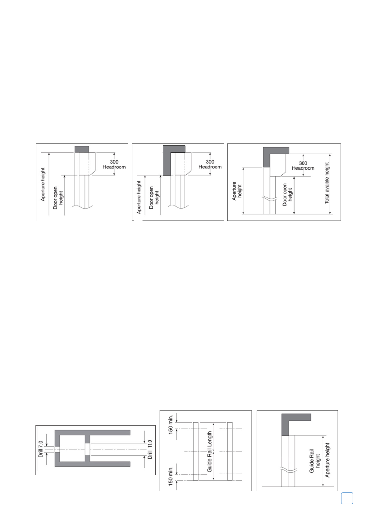
2. Check Headroom
3. Preparing the Guide Rails
The headroom is the clear vertical height required between the top of the guide rails and any obstruction
above the shutter as shown in Fig 1 and Fig 2.
This space is required to house the door roll headroom of 205mm / 300mm is required. (AG55 requires 205mm
& AG77 requires 300mm).
Limited Head room
If insucient headroom is available the door can still be tted (see your survey sheet) but the shorter guide
rails will give a corresponding reduction in door opening height as shown in Fig 3. The curtain will require 1
lath to be removed for every 75mm of reduction in the guide height.
Note: Ensure that the headroom above the guides is clear of any obstructions (especially small protrusions or
nail heads) which could cause damage to the door roll during installation/operation.
3.1 For Fitting Within The Aperture
3.1.1 Check Guide Rail Length
Check that guide rails have been supplied to the correct length as per your survey sheet / order. The correct
length is aperture height less 205mm or 300mm as shown in Fig 1.
3.1.2 Drill Fixing Holes
Drill holes through 7mm diameter and counter drill 11mm diameter as shown in Fig 4.
A minimum three holes per rail are required, positioned as shown in Fig 5.
NB. Position holes for best xing to brickwork.
3.2 For Fitting Behind The Aperture
3.2.1 Check Guide Rail Length
Check that guide rails have been supplied to the correct length as per your survey sheet/order.
A. Where headroom of 205mm / 300mm or more is available guide rail length equals aperture height as
shown in Fig 6.
B. Where only limited headroom is available guide rail length equals total available height less 205mm /
300mm as shown in Fig 7.
Fig 1: Headroom within aperture
Fig 4
Fig 2: Headroom behind aperture
Fig 5
Fig 3: Limited headroom
Fig 6

6 7
4. Assemble the Frame
3.2.2 Drill Fixing Holes
Drill holes through 7mm diameter & counter drill 11mm diameter as shown as shown in Fig 8.
A minimum three holes per rail are required as shown as shown in Fig 9.
NB position holes for best xing to brickwork.
4.1 L/H or R/H Motor (Factory Fitted as Standard)
The motor and control unit can be mounted on either the L/H side or R/H side. (Please specify at time of order).
All AlluGuard doors are tted with a safety brake as standard excluding AG55 Doors shown in Fig 10.
• If you want to change the hand of the motor this should be carried out by a suitably trained engineer.
• If you do move the Motor & Safety Brake ensure that these are installed correctly otherwise the unit will not
activate under normal running conditions.
• It is important that the head plates are securely xed – 2 xings per head plate.
4.2 End Plates and Safety Brake Device* (Safety brake factory tted as Standard)
Lay the Head assembly on protective packing, parallel with and just inside the
garage opening.
Ensure the motor is situated at the correct end for your installation and that the
motor limit adjusters are at the top/bottom as shown in Fig 11.
Fix the motor plate to the end plate by using four M6 x 25 countersunk screws
and Nyloc nuts provided.
Fig 7 Fig 8 Fig 9
Shaft
Safety Brake
Safety Collar
Safety Collar Safety Collar tight against
the dummy end
Dummy End
Fig 10
Fig 10a
Fig 10b Fig 10c
Fig 11

6 7
5. Install the Frame
You will have drilled your guide rails, as shown in Fig 4 or Fig 8, for tting either:-
a) Within the aperture b) Behind the aperture
Please proceed accordingly. (SAFETY NOTE: 2 people required)
5.1 Fitting Within Aperture
For installation within the aperture we strongly recommend the use of a cover box as this covers and protects
the door curtain roll.
5.2 If either half box or full box options are specied these will be supplied factory tted to the end plates.
5.3 Lift the frame assembly into position and align with the front of
the aperture.
Ensure the guide rails are VERTICAL (in both directions) and parallel
to each other, at the same height and the correct distance apart.
NB: Some width adjustment is available on the sliding shaft end of
the axle.
The correct distance is shown in Fig13. – AG77 Door
Ensure the axle assembly is horizontal by using a spirit level.
5.1.3 Once the frame is correctly positioned, mark and drill for xings (xings not supplied).
5.1.4 When the guide rails are securely xed, double check that they are vertical, parallel and correct distance
apart and that the axle assembly is level.
5.4 Fixing The Head Plates – 2 xings per head plate.
Fix the head-plates into position ensuring that the head-plates are level and that the locating pegs are fully
located into the guide section. Fix securing screws through back of head-plate and attach securely to the wall.
Where a back box is tted it may be necessary to x the back box to the opening header to stop any marking
of the curtain during door operation. If additional xings are required in the back box, use countersunk screws,
ensuring that the screw heads do not protrude, as curtain damage could occur.
Always ensure that the back box is adequately xed to eliminate any rubbing of the curtain on the
back box during the door operation and xing are evenly spaced to ensure no bowing of the box.
The safety brake is pretted to the end plate as standard (Fig 10). Loosen the safety collar on the dummy end
shaft, extend the shaft fully into the safety brake (Fig 10a). Slide the safety collar tight up to the dummy end
and tighten.(Fig 10b & 10c).
4.3 Fit Guide Rails
Select R/H guide rail and slide fully onto the bottom square tube spigot projecting from the R/H end plate,
please ensure that the End Plate is ush with the face side of the guide rail.
Repeat for the L/H guide rail as shown in Fig 12.
Fig 12
Fig 13
R/HL/H

8 9
5.5 Fitting Behind Aperture / Fitting to the Front of the Aperture (External Fit)
Lift the frame assembly into position and align centrally with the aperture. Ensure the guide rails are vertical (in
both directions) and are parallel to each other, at the same height and the correct distance apart.
NOTE: Some width adjustment is available on the sliding shaft end of the axle. The correct distance apart is
shown in Fig 13.
When tting to the front of the aperture (external t/reverse roll), once installation is complete, the
box must be siliconed at the interface with the aperture and along all edges and joints to prevent
water ingress. Failure to seal will invalidate the warranty. The bottom slat transmitter must be tted
to the inside face of the bottom slat (concave face). Fitting to the external face of the slat will lead to
failure and invalidate the warranty.
Ensure axle assembly is horizontal by using a spirit level.
5.6 Once the frame is correctly positioned, mark and drill for xings (xings not supplied).
5.7 When guide rails are securely xed, double check for vertical, parallel and correct spacing and that the axle
is level.
NOTE: Once the frame is fully tted and checked, use the plastic plugs supplied to cover the xing holes in the
guide rails to give a‘fully nished’ eect.
5.8 Fixing the Head Plates
Fix the head-plates into position ensuring that the head-plates are level and that the locating pegs are fully
located into the guide section. Fix securing screws through back of head-plate and attach securely to the wall.
Where a back box is tted it may be necessary to x the back box to the opening header to stop any marking
of the curtain during door operation. If additional xings are required in the back box, use countersunk screws,
ensuring that the screw heads do not protrude, as curtain damage could occur.
Always ensure that the back box is adequately xed to eliminate any rubbing of the curtain on the
back box during the door operation.
6. Installing the Curtain Assembly
6.1 Carefully unwrap and remove the outer bubble wrap protection and place over shaft to stop damage to
inside of curtain during installation.
6.2 Carefully position the curtain assembly in the door
aperture, below the axle as shown in Fig 14, slit the
packaging to gain access to the curtain but leave some
packaging to protect the curtain.
6.3 SAFETY NOTE: A minimum two people are required
for this procedure to ensure safe handling.
6.4 It is essential to place sections of bubble wrap over the
axle to prevent marking the curtain as it is installed.
6.5 Using minimum 2 people carefully lift the curtain
assembly up level with the axle. Practice has shown that it
is best to place one hand on the axle, keeping that arm straight, and support the curtain roll on that shoulder
as shown in Fig 15.
6.6 Feed the bottom lath over the top of the axle and down between the guide rails, as shown in Fig 16 taking
care not to scu the curtain assembly, proceed until half of the curtain has been fed over the axle, carefully
unroll the remaining curtain until this is balanced over the shaft, once this is done carefully feed the curtain
into the guide until the curtain is reaches the oor.
NOTE: Do not let the curtain ‘free fall’ over the axle as this will result in damage to the Curtain and/or the
Safety Edge Transmitter.
Fig 14

8 9
7. Attach the Curtain
7.1 Fit the Motor Override
Attach the ‘Motor Override Eye’ tting to the motor as shown in Fig 17 using
3mm screw.
7.2 Position the Axle
Use the motor override to rotate the axle shaft.
Rotate the axle until the locking joint attachment holes are positioned as
shown in Fig 18.
7.3 Locking Ring
There is a locking ring positioned on the shaft for each locking strap; the
number of locking rings will vary according to curtain width and AG55 - 2
rings & AG77- 1 ring per strap.
Position the outermost ring/s to the shaft approx. 150mm in from each end
and equally space the other/s as shown in Fig 19.
Slide each locking strap along the top lath and engage the fastening pin into
the appropriate hole in the respective clamped locking ring/s, (AG55 Doors).
Slide the loose locking ring to engage the other end of the fastening pin and secure the loose locking ring to
the shaft using the self tapping screw on AG55 doors.
Repeat this for each locking strap, as shown in Fig 19.
7.4 Locking Ring (AG77)
The locking rings are pre-attached on the barrel, to connect the locking straps, line up with the locking ring
hole and insert pin. Space the lock rings with 800mm between them.
Fig 15 Fig 16
Fig 17
Fig 18 Fig 19
10 11
8. Connect the Electrics
9. Setting the Curtains Open
and Close Position
8.1 Preparing the AlluGuard Roller Garage Doors for Remote Control for
Installation
• Remove the integrated light cover from the top of the Somfy Rollixo Control
Unit.
• Unscrew and remove the receiver cover from the unit by loosening the one
screw at the base of the unit.
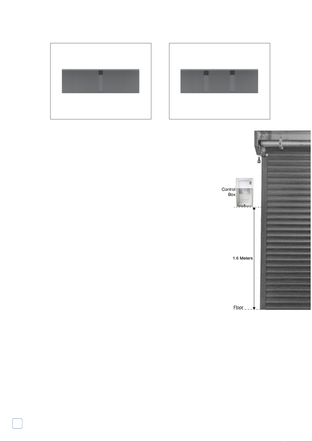
8.2 Fixing the Somfy Rollixo Remote Control to the Wall
• Make sure that the unit is mounted onto internal brickwork and is rmly xed.
• The unit must be installed with the courtesy light at the top. Hold the unit
against the wall at a height of at least 1.6 meters and mark where the screw
xings should be as shown in Fig 20.
• Take the unit away and drill the holes. Fix unit to the wall.
THIS MUST BE FITTED INSIDE THE GARAGE AS IT IS NOT IP RATED
8.3 Plug power lead into 13A socket but DO NOT SWITCH ON at this stage.
8.4 Connect the safety brake cable to terminals 5 and 6. Alternatively use a
test lead.
Somfy Motor Set-Up
Motor and fall protection wiring.
The receiver must not be connected to the mains power supply during connection to the motor.
9.1 Motor Wiring
9.1.1 Connect the motor to the receiver.
Note: the motor’s direction of rotation shall then be checked and reversed if necessary.
9.1.2 Lock the motor cable with the cable clamp provided.
The motor cable must be placed in the receiver’s 230v insulation area.
Fall protection wiring.
If no fall protection is connected, it is essential to create the bridge between terminals 5 and 6
of the receiver (with the shunt provided).
The support straps (box stieners) should be positioned centrally or equidistant. Support straps are
available as an optional extra, should the box require support.
Fig 20

10 11
9.2 Connecting the Receiver to the Mains Power Supply
9.2.1 Fully unfold the receiver aerial so that it is pointing downwards.
9.2.2 Screw the bulb supplied into the receiver. (Before connecting to mains power supply)
9.2.3 Replace and screw in the receiver cover.
9.2.4 Ret the integrated light cover.
9.2.5 Connect the receiver to the mains power supply.
All the indicator lights come on and then go out.
If indicator light 1 comes on permanently, fall protection is not connected or incorrectly connected to the
receiver.
If indicator light 2 comes on permanently, the safety edge has not been detected by the receiver (radio safety
edge transmitter not yet memorised or the wired safety edge is still not connected).
9.3 Checking the Direction of Rotation of the Motor and Adjustment of the Motor End Limits
9.3.1 Press simultaneously on the ^ and v buttons until the motors up and down movement occurs to enter
motor adjustment mode.
• Indicator light 1 ashes slowly.
9.3.2 Press button ^ or v to check the motor’s direction of rotation.
If the motor’s direction of rotation is correct, move on to step [3] of the motor end limit setting procedure.
If the direction of rotation is incorrect, press button (stop) until the motors up and down movement occurs,
check the motor’s direction of rotation again and move on to step [3] of the motor end limit
setting procedure.
9.3.3 If the motor end limits are already set, move on to step [8] to exit motor adjustment mode.
• If the motor end limits are not set, check that the motor is released: the two push-buttons should
be pressed.
Note: The motor end limits can also be set with a setting tool (ref. 9015971).
In this case, set the motor end limits with the cable then move on to step [8] to exit motor adjustment mode.
9.3.4 Press ^ button to position the garage door in the upper position.
• Adjust the upper position with buttons ^ and v.
9.3.5 Press the motor’s upper end limit push-button.
9.3.6 Press v button to position the
garage door in the lower position.
• Adjust the low position with
buttons ^ and v.
9.3.7 Press the motor’s low end limit
push-button.
9.3.8 Press simultaneously on the ^
and v buttons or press the (prog)
button until the motor’s up and down
movement occurs to enter motor
adjustment mode.
• Indicator light 1 goes out.
Somfy Motor
12 13
Progressive Motor Limit Set-up
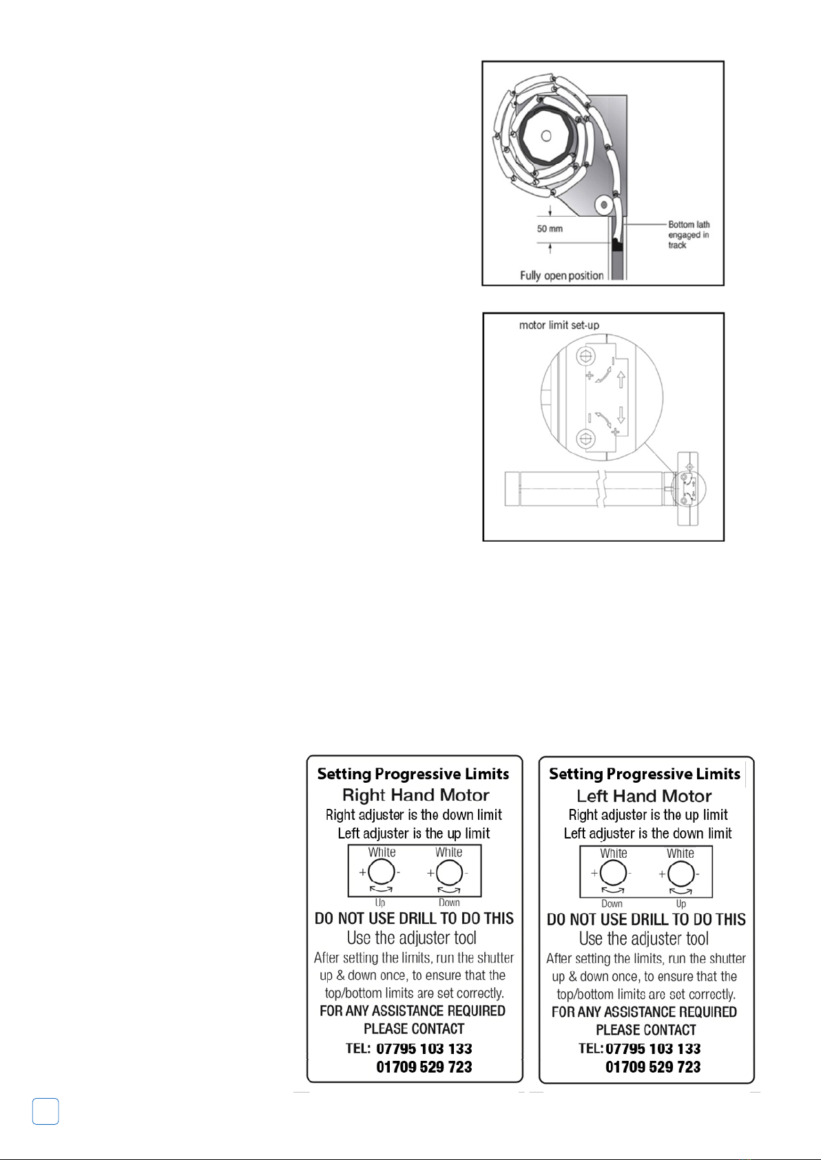
9.4 Limit Switch Adjustment (see Fig 22)
The limits are set at the factory to 8 revolutions of the shaft, A 4mm
‘Allen Key’ limit adjuster is used to adjust them further.
Allow the motor to run downwards without the curtain attached
to enable the shaft to determine bottom limit position, without
curtain attached to shaft.
9.5 Adjustment ‘Up’
Run the motor up with the curtain attached, if the motor stops
short of fully open, turn the adjusting screw in the + direction (this
is the adjuster indicated by the rotation of the barrel. This will allow
the motor to run on in the up direction.
Stop the motor before it gets to the fully open position and wind
the adjuster in the – direction until it stops before the fully open
position. Keep the open button pressed and at the same time
slowly turn the adjuster in the + direction until the door stops
at the fully open position. If the motor runs too high, turn the
adjustment screw towards the - direction until the motor stops in
the correct position.
9.6 Adjustment ‘Down’
Run the motor down, if the motor stops short of the closed
position, turn the adjustment screw towards the + direction
keeping the control pressed in the down direction until the correct
position is reached.
If the motor runs too far turn the adjustment screw towards the –
direction.
Set open position as shown in Fig 21.
9.7 Checking the Limit Positions
Run the motor in both directions until the limit switches cut out the motor travel.
Carry out any ne adjustments. One turn of the adjustment screw corresponds to approximately 70° turn
of the roller tube.
In order that the locking joints
operate eectively, the position
of the shaft in the closed position
needs to be nely adjusted.
Do not adjust past this position as
this will impose excessive loads on
the mechanism.
This motor is tted with a thermal
trip; this stops the motor from
overheating.
Be aware that excessive running of
the door may cause the thermal trip
to operate, if this happens; please
wait 20 minutes before trying to
operate the door again.
Fig 21
Fig 22

12 13
Programme the bottom slat transmitter into the control box Fig 24.
Programming the XSE Transmitter in to the Rollixo Receiver
Press the ‘Prog’ button on the Rollixo RTS front panel until the LED above the Prog button lights up RED.
Press the ‘PROG’button on the safety edge transmitter for approximately 4 seconds until the ‘Prog’ LED on
the Rollixo RTS controller ashes and then goes out.
Now, using the control box, send the door up to its open position. Then, using the down arrow, send the
door, in one movement, all the way to the close position. The bottom slat transmitter should switch o
about 10 seconds after closing.
Failure to follow this procedure can cause the alarm to sound a short while after installation.
Once the safety edge transmitter is in full working order then x the magnet in place using the self
tapping screws provided
Please refer to the Somfy instructions on commissioning a safe edge if required. If you require support, call
Somfy Technical Assistance on: 0113 391 3030 Option 3
10. Position the Magnet on the Door Guide &
Programming the Safety Edge Transmitter
IMPORTANT: Do not introduce the bottom magnet to the guide for the rst time with the curtain in the
closed position, this will compromise the set up process. Using the test lead or control box buttons, send
the door down to the bottom limit position. Mark the guide in pencil at the point in line with the arrow on the
bottom slat transmitter. Open the door half way. Fit the bottom magnet over the mark using the sticky pad as
shown in Fig 23.
Fig 24
Fig 23

14 15
Additional Problem Solving
10.1 Door Tight Or Jams In Operation
• Check for good entry of curtain laths into guide rails.
• Check that bottom lath is correctly engaged into track when fully open, as shown in Fig 21.
• Check for correct clearance of curtain in guide rails. NB: laths should have a sideways ‘end oat’ of
approx 6mm.
• Adjust guide rails if necessary to achieve free movement.
10.2 Recalibration of the bottom slat transmitter required
• Press and hold the mode button = LED ash red
• Release the mode button = LED solid red
• Allow the left LED to ash green
• Allow the right LED ash green
• Immediately press the safety edge twice in quick succession to activate it. The LED should ash red
then go solid green if the transmitter has been reset.
Rollixo RTS XSE Kit Contents
The Rollixo XSE Kit is supplied with the following:
No. Description
1. 1 x Rollixo RTS Controller
2. 1 x Rollixo RTS Installation Guide
3. 1 x Rollixo RTS End User Guide
4. 1 x Quick Fit Mains Supply Cable
5. 1 x Wiring Accessory Bag – Contains:
1 x Motor Supply Cable Clamp & 2 x Cable
Clamp Screws
1 x Wire Link (to bridge the safety brake
terminals)
1 x Alarm Sounder Screw
6. 2 x Keygo 4 RTS Radio Keyfobs
7. 1 x Courtesy Light Bulb
8. 1 x XSE Safety Edge Transmitter
9. 1 x XSE Safety Edge Transmitter
Installation Guide
10. 1 x Bag of XSE Safety Edge Transmitter
Screws (x4)
11. 1 x Guide Magnet
14 15
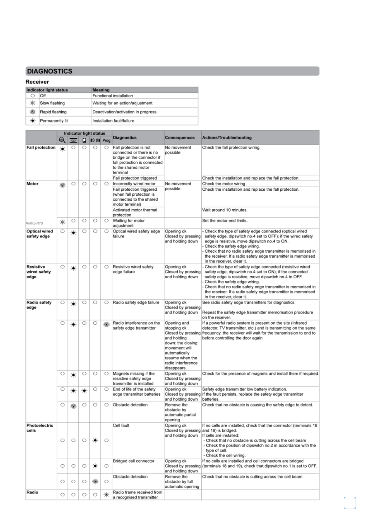
System Diagnostics
The Rollixo Remote Control System provides a full fault nding diagnostic programme,
this is all dependent on there being power to the unit.
Do not attempt to work on the door unless
you are a trained engineer
Somfy Technical Assistance - t: 0113 391 3030 Option 3
16 17
Teleco Quick Setup
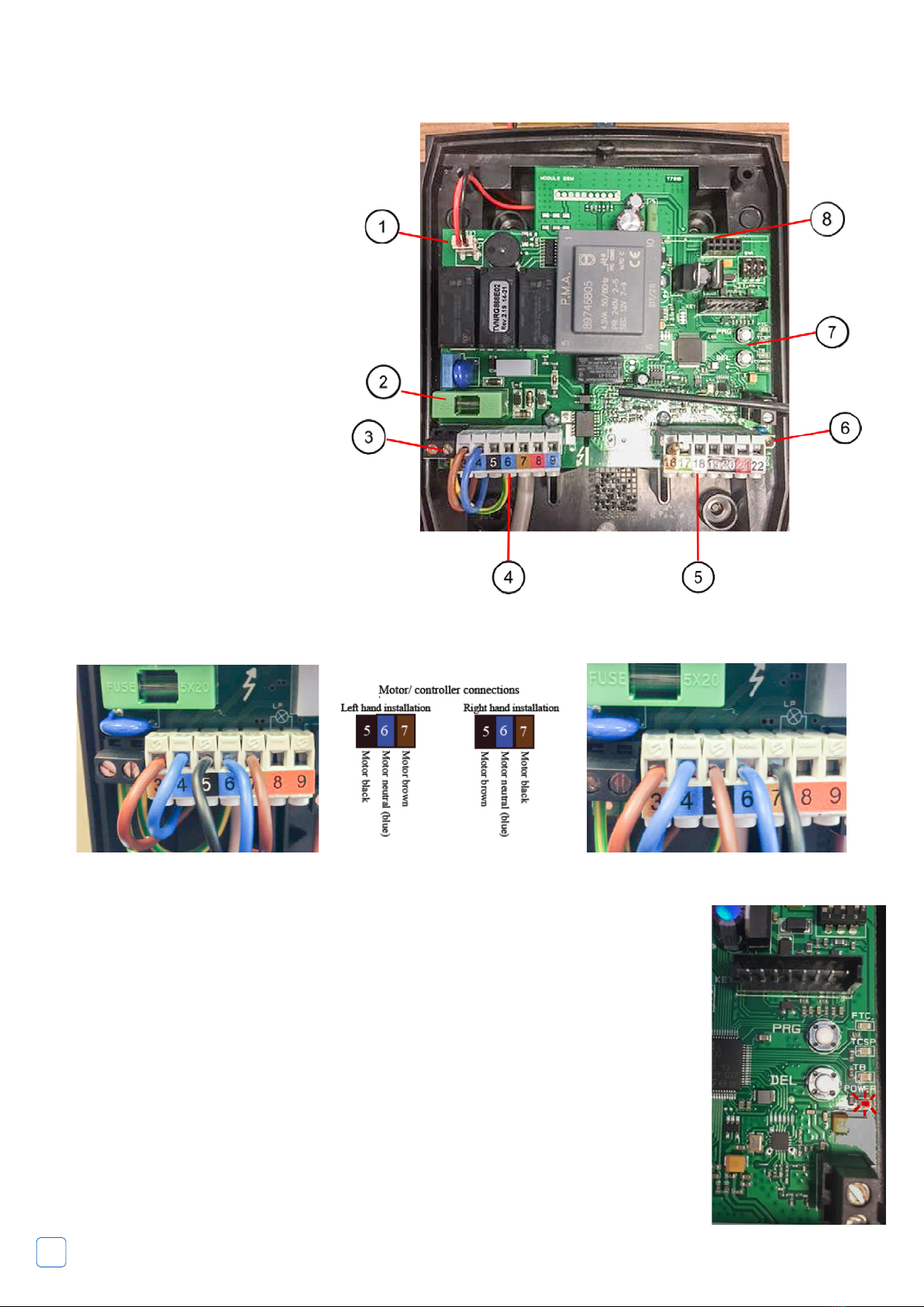
Knowing your way around
the board
1. LED Lighting
2. Fuse
3. Mains
4. Motor Cable
5. Wired Edge Terminal & 8.2k Resistor
6. Alarm Sounder Socket
7. Program & Delete Buttons
8. Radio Card Slot
Connecting the motor cable
Left hand motor
NOTE
: First
operation of the garage door is always in the up
direction.
If the door is travelling in the wrong direction -
Black and Brown (terminals 5 & 7) swap them round!
Setting motor limits
• After you have connected the motor cable to the correct orientation, turn the power on.
• The power light (next to the DEL button)should be ashing.
(if not press both PRG & DEL buttons together for 3 seconds)
• Press and hold the DEL button and drive the door to closed position and set the limit.
• Press the PRG button and drive the door to the fully open position and set the limit.
• Once you have set the limits check the limits and then press the PRG/DEL together for 3
seconds to go back to normal running mode.
Right hand motor
16 17
Testing the bottom slat transmitter and wiring
The bottom edge can be tested to conrm if the wiring and bottom slat transmitter are functioning correctly.
• Squeeze rmly the bottom edge rubber.
The blue light should be on as normal.
Red light on will activate upon
each squeeze.
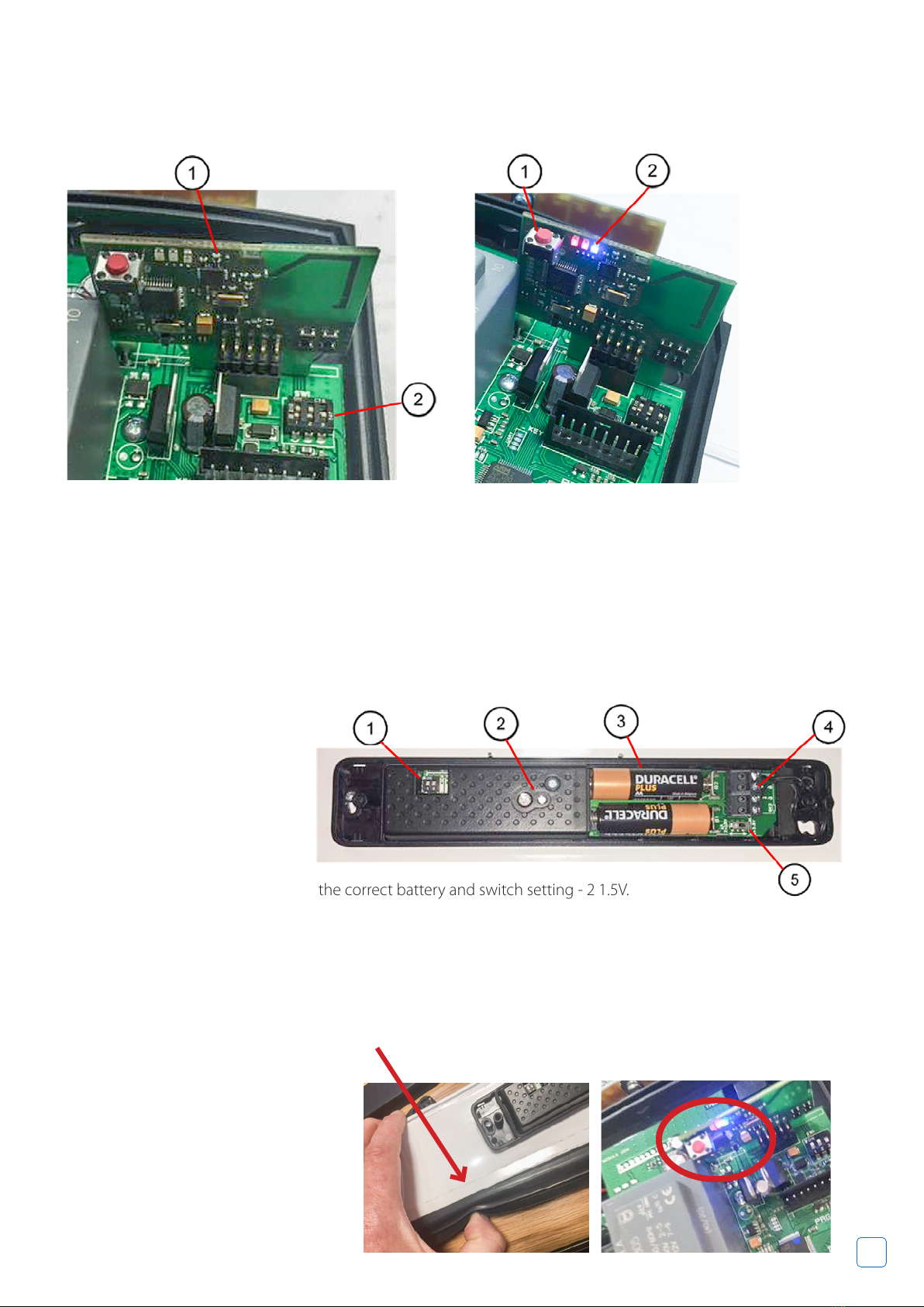
Bottom slat transmitter
Red and Blue light indicates that the card has not been paired with the BST. When BST is paired there
should only be a blue light ashing!
• Press the red button, the LEDS ash.
• Press the PRG button on the outside of the BST.
• The Blue LED light on the radio card should be ashing.
NOTE: Ensure that you have chosen the correct battery and switch setting - 2 1.5V.
• DIP1 o Dip2 o.
• Press and hold the white button to check you have power.
Use handsets (pre-programmed) to send the door up and down.
1. Radio Card
2. Control Board Dip Switches
1. Dip 1 O & Dip 2 O
2. Programme Button For Pairing
& LED Light
3. 1.5 V Batteries
4. Terminal Block 3-6
5. Battery Section Switch
1. Radio Card with Red Program Button
2. Blue & Red LED light

18 19
Sommer Quick Setup
Wire the motor
Motor on the left side
of the door.
Motor on the right
side of the door.
Before starting set the motors mechanical limits.
NO
1 23
4
MEMO/
SENSO
DOORSCOUT
BUZZER LUMI
SAFETY
KEYPAD
USART
LASER
RESET
RADIO
CH1
STATUS
CH2
CH3
CH4
MUFU
OPEN
CLOSE
STOP
COM
FUNCTION
F2
F1
1AT
4AT
X1 X2 X3 X4 X5 X6
X7
L1 N
N
M
24V
GND
24V
GND
SIGNAL
COM
VES
8K2
gn
bn
12V
wh
OSE
IMP
ARS
STOP
Check the direction of the motor is correct
With the front cover button at ex cable connection removed,
use the up and down hold-to-run buttons at the top of the PCB to
check the direction of the motor is correct.
Also use these buttons to test the top and bottom motor
mechanical limits and make ne adjustments.
Positioning the magnets
Position the
magnetic switch
on the guide
rail, facing the
opening, at
approximately
50mm from the
oor.
Position the
magnet on the
bottom lath so
that it faces the
switch on the
guide rail when
the door is
closed.
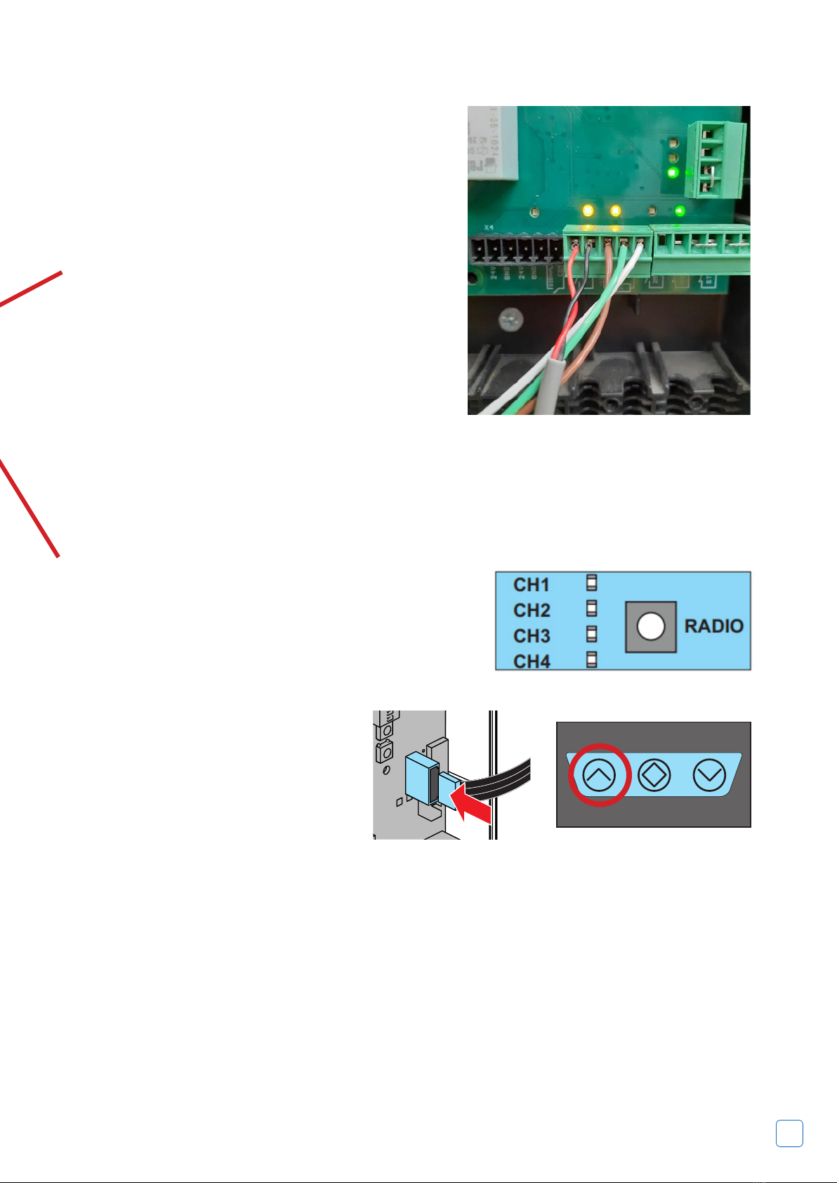
Wiring in the door box
1. Spiral Cable Wires
2. Pairs of Wires From Optical Safety Edge
The wiring in the door box should be as per the picture
right. The brown, green and white wire pairs from
the optical safety edge eyes should be wired to the
corresponding brown, green and white wires of the
spiral cable.
18 19
Wiring the magnetic switch
The red and black cables from the magnetic switch wire
into the left 2 connections on the green connector to the
spiral cable marked VES.
The brown, green and white spiral cable wires should be
connected as shown.
You will get a solid orange light above each connection,
when the device is triggered the orange light will ash.
Test the safety edge
• Press the rubber edge and the orange LED above the
OSE connection should ash. It will return to a solid
light when the edge is released.
• Move the door to the half open position.
Once done, the door will stay open and the white LEDs will be on solid.
(If the LEDs are ashing it is likely that the safety edge triggered on the oor as it is uneven. The
magnetic switch should disable the safety edge for the last 50mm to prevent false triggering. Check
this is operating correctly and reposition if needed.)
If the version of RCD Vision+ you have includes the Alarm buzzer accessory in the top of the housing, the
magnetic switch also triggers the alarm.
• With the door closed and power on, lift the curtain by hand or use the emergency manual winding handle
to raise the door. As the magnetic switch is trigger in the up direction, the RDC recognises that it is not the
motor that is raising the door, so sounds the alarm.
• To silence the alarm, press the button on one of the coded handsets.
• Test the door and make sure the safety edge responds correctly to an obstacle.
NOTE: The edge should be tested at least once a month.
Code in the handsets
• Press the RADIO button once, CH1 lights up.
• Press the handset button needed to operate this door.
• The CH1 LED blinks and goes out.
• Repeat the above for all handsets.
Start the automatic set up
• Plug in the front button ribbon cable and
t the front cover.
• Press the UP button on the front cover to
start the automatic setup. The door goes
up to the top, down to the oor and back
to the top.
20 21
Electrically Operated Products
Under UK Legislation the garage door should be operated when it is in view (unless tted
with additional safety equipment e.g. for smart phone operation), making sure it is not
obstructed. Ensure when the door is running, that you and any other person stands clear of
the curtain and keeps hands etc. away from the moving parts. Children should not operate
the door or play nearby an opening door.
Control Unit
Please note the front of the control unit should only be removed by a trained engineer.
Your garage door can be activated by pressing and releasing the buttons on the front of
the control unit, the button on your remote handset, or a separate wall switch that you may
have installed.
Hand Transmitters
The transmitters are tted with buttons and when any button is pressed the LED illuminates.
The buttons on remotes can be programmed to suit your requirements (dependent on
handset type). The default setting is one button operation that allows you to lift, stop and
close the door.
PLEASE NOTE
When opening or closing the garage door you must monitor the product until it has
completed its operation. If the product is tted with a safety device this could be activated
during its operation which would cause the door to stop and reopen a short distance
leaving the door partly open.
Batteries
The expected life span of batteries is 2 years; however high usage of the door will lead to a
decrease in this. Batteries are not covered under warranty.
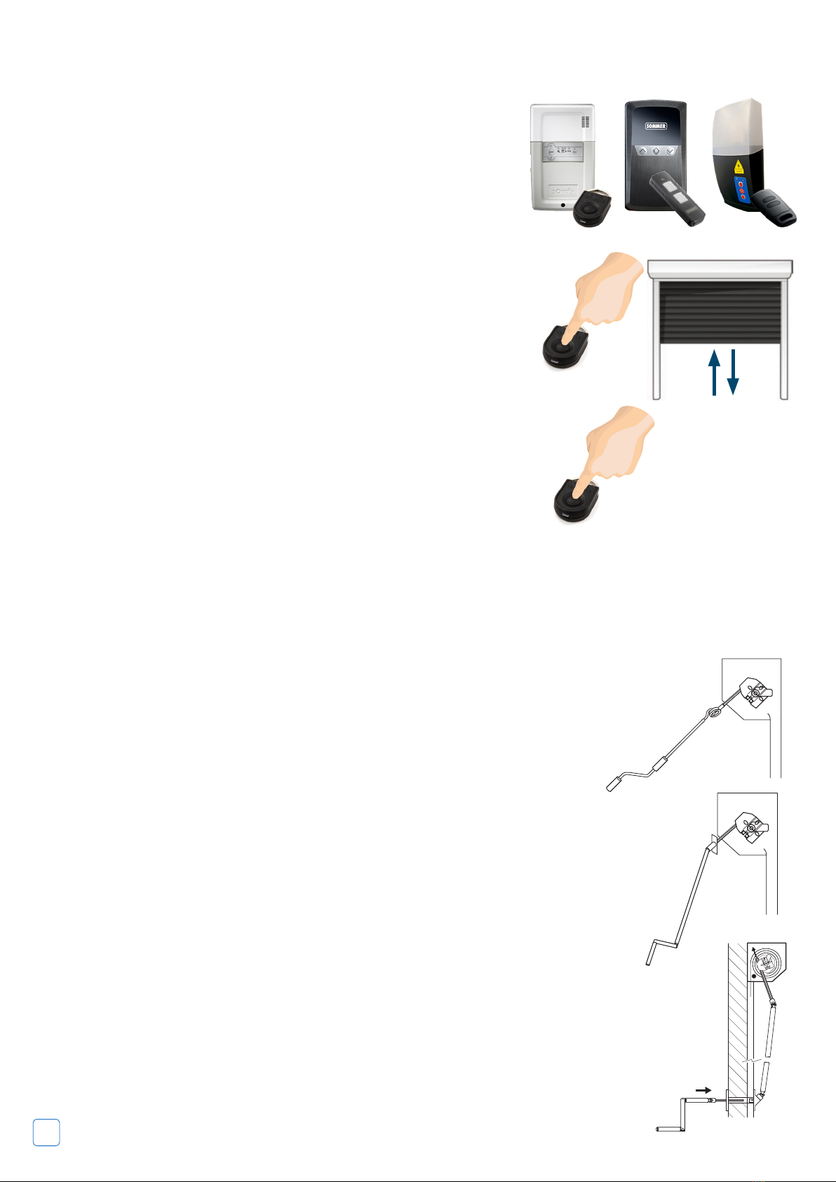
Press & let go
Press & hold
This type of operation is
required for “dead man
mode”, see the note*** at
the foot of page 7 for an
explanation of its use.
Safety & the Safety edge
The Safety Edge is tted to the bottom of the door and is activated when the door starts to close. If it comes into contact with an object
while the door is closing, it transmits a signal to the wall mounted control unit, the door will then stop and reopen a short distance. The
safety edge also works as a weather seal, designed to be pressed against the ground. The bottom slat transmitter\cable has an IP rating
of IP54 and is protected against dust and water splashing. The standard remote control receiver unit is supplied with either an electrical
wireless safety edge or optical wired safety edge.
To operate:
Hold crank handle in
line with eye and rotate
handle until the door
reaches the open/
closed position.
To operate:
Externally tted doors will need the cover cap or
override lock removing and the crank handle inserting.
Rotate handle until the door reaches the open/closed
position.
To operate:
Remove lock and insert crank handle and rotate until
door reaches the open/close position.
DO NOT OVERWIND
When the main power is reinstalled, ensure that
the power isolator is switched back on. If applicable
secure the handle back onto the wall. Remember to
keep the crank handle in a convenient place.
Power Failure
Electrically Operated Products
If your roller garage door is not working correctly please contact
your installer for assistance. N.B: Always isolate the power
before attempting to make an adjustment or repair. Untrained
operators are advised to contact an approved installer.
Power failure
In the event of disruption to the power supply, or the motor
temporarily over heating (the motor is protected by a thermal
cut out), the door can be operated manually. Isolate power
supply before using the manual override.
To operate: Hold crank handle in line with eye and rotate handle
until the door reaches the open/closed position.
If the door is not used during the power failure then no action
has to be taken as the unit will reset itself when the power is
restored.
Important
If the garage has no service door then an exterior release kit should
have been tted to allow emergency opening from outside. Follow
instructions supplied with that kit.
Note
When closing the door manually ensure that the locking joints are set in
the fully closed position to ensure security.
Insert the hooked end of the winding handle into the override eye; this
is projecting downwards from the drive motor at one end of the curtain
roll, rotate the handle to operate the door to open or close.
Operating Instructions
This manual suits for next models
1
Table of contents
Other Stella Bathroom Fixture manuals


Popular Bathroom Fixture manuals by other brands

Kohler
Kohler Mira Sport Max J03G Installation and user guide

Moen
Moen 186117 Series installation guide

Hans Grohe
Hans Grohe Raindance Showerpipe 27235000 Instructions for use/assembly instructions

Signature Hardware
Signature Hardware ROUND SWIVEL BODY SPRAY 948942 Install

fine fixtures
fine fixtures AC3TH installation manual

LIXIL
LIXIL HP50 Series quick start guide


