Stella S-C3 User manual

Model S-C3
Machine Code:
B262/B280/B292/B293
SERVICE MANUAL
June 30th, 2006
Subject to change

Safety Notice
Important Safety Notices
Prevention of Physical Injury
1. Be sure that the power cord is unplugged before disassembling or assembling parts of the copier or
peripherals.
2. The wall outlet should be near the copier and easily accessible.
3. Note that electrical voltage is supplied to some components of the copier and the paper tray unit even
while the main power switch is off.
4. If you start a job before the copier completes the warm-up or initializing period, keep hands away
from the mechanical and electrical components until job execution has started. The copier will start
making copies as soon as warm-up or initialization is finished.
5. The inside and the metal parts of the fusing unit become extremely hot while the copier is operating.
Be careful to avoid touching those components with your bare hands.
Health Safety Conditions
Toner and developer are nontoxic, but getting either of these into your eyes may cause temporary eye
discomfort. Try to remove with eye drops or flush with water. If material remains in eye or if discomfort
continues, get medical attention.
Observance of Electrical Safety Standards
The copier and its peripherals must be installed and maintained by a customer service representative who
has completed the training course on those relevant models.
• Keep the machine away from flammable liquids, gases, and aerosols. A fire or an explosion might
occur if this precaution is not observed.
Safe and Ecological Disposal
1. Do not incinerate toner bottles or used toner. Toner dust may ignite suddenly if exposed to an open
flame.
2. Dispose of used toner, developer, and organic photoconductors in accordance with local regulations.
(These are nontoxic supplies.)
1

3. Dispose of replaced parts in accordance with local regulations.
Laser Safety
The Center for Devices and Radiological Health (CDRH) prohibits the repair of laser-based optical units
in the field. The optical housing unit can only be repaired in a factory or at a location with the requisite
equipment. The laser subsystem is replaceable in the field by a qualified Customer Engineer. The laser
chassis is not repairable in the field. Customer engineers are therefore directed to return all chassis and
laser subsystems to the factory or service depot when replacement of the optical subsystem is required.
• Use of controls not specified in this manual, or performance of adjustments or procedures not specified
in this manual, may result in hazardous radiation exposure.
WARNING FOR LASER UNIT
• Turn off the main switch before attempting any of the procedures in the Laser Unit section. Laser
beams can seriously damage your eyes.
CAUTION MARKING:
2
Symbols and Abbreviations
This manual uses several symbols and abbreviations. The meaning of those symbols and abbreviations is
as follows:
*See or Refer to
Clip ring
E-ring
Screw
Connector
Clamp
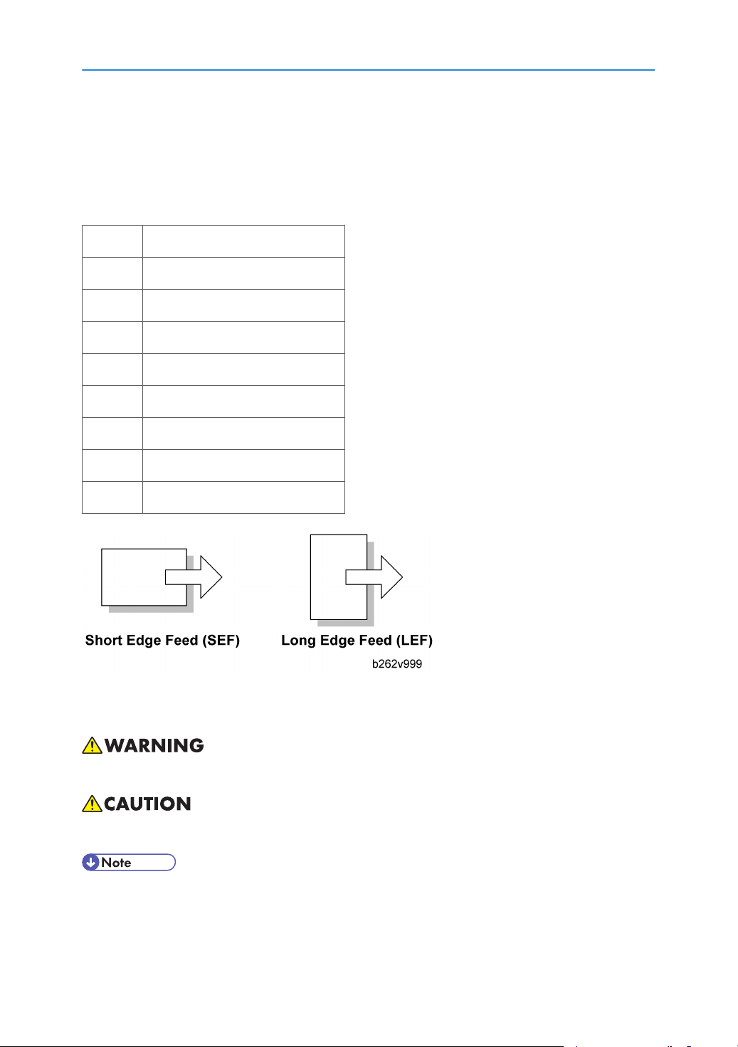
SEF Short Edge Feed
LEF Long Edge Feed
Core Technology manual
Cautions, Notes, etc.
The following headings provide special information:
• FAILURE TO OBEY WARNING INFORMATION COULD RESULT IN SERIOUS INJURY OR DEATH.
• Obey these guidelines to ensure safe operation and prevent minor injuries.
• This information provides tips and advice about how to best service the machine.
3

TABLE OF CONTENTS
Safety Notice......................................................................................................................................................1
Important Safety Notices..........................................................................................................................1
Laser Safety.....................................................................................................................................................2
Symbols and Abbreviations...............................................................................................................................3
1. Installation
Installation Cautions.........................................................................................................................................11
Installation Requirements.................................................................................................................................12
Environment..................................................................................................................................................12
MACHINE LEVEL.........................................................................................................................................12
Minimum Operational Space Requirements.............................................................................................13
Power Requirements....................................................................................................................................14
Copier...............................................................................................................................................................15
Accessory Check..........................................................................................................................................15
Installation Procedure..................................................................................................................................16
Paper Tray Unit.................................................................................................................................................21
Accessory Check..........................................................................................................................................21
Installation Procedure..................................................................................................................................21
Paper Tray Unit Heater....................................................................................................................................23
Accessory Check..........................................................................................................................................23
Installation Procedure..................................................................................................................................24
ARDF (B872)....................................................................................................................................................31
Accessory Check..........................................................................................................................................31
Installation Procedure..................................................................................................................................31
DDST Unit (B880/893)..................................................................................................................................38
Accessory Check..........................................................................................................................................38
Installation Procedure..................................................................................................................................39
2. Preventive Maintenance
PM Tables.........................................................................................................................................................43
How to Clear the PM Counter.........................................................................................................................45
3. Replacement and Adjustment
Precautions........................................................................................................................................................47
General.........................................................................................................................................................47
Halogen-free Cable....................................................................................................................................47
4

Special Tools and Lubricants...........................................................................................................................48
Exterior Covers and Operation Panel............................................................................................................49
Rear Cover...................................................................................................................................................49
Copy Tray.....................................................................................................................................................49
Scale Plate....................................................................................................................................................50
Operation Panel and Upper Covers..........................................................................................................51
Right Door.....................................................................................................................................................52
Bypass Tray..................................................................................................................................................52
Platen Cover Sensor....................................................................................................................................53
Scanner Unit.....................................................................................................................................................54
Exposure Glass............................................................................................................................................54
Lens Block.....................................................................................................................................................55
Exposure Lamp, Lamp Stabilizer Board.....................................................................................................55
Scanner Motor.............................................................................................................................................56
Scanner HP Sensor......................................................................................................................................58
Scanner alignment adjustment....................................................................................................................58
Fusing................................................................................................................................................................60
Fusing Unit....................................................................................................................................................60
Exit Sensor....................................................................................................................................................61
Hot Roller Stripper Pawls.............................................................................................................................61
Hot Roller & Fusing Lamp............................................................................................................................62
Thermoswitches and Thermistor..................................................................................................................64
Pressure Roller..............................................................................................................................................65
Checking the NIP band...............................................................................................................................66
PCU and Quenching Lamp.............................................................................................................................67
PCU...............................................................................................................................................................67
Quenching Lamp..........................................................................................................................................68
Exhaust Fan and Main Motor.........................................................................................................................69
Exhaust Fan..................................................................................................................................................69
Main Motor..................................................................................................................................................70
Paper Feed........................................................................................................................................................71
Paper Feed Roller and Friction Pad............................................................................................................71
Paper End Sensor.........................................................................................................................................72
5

Registration Sensor......................................................................................................................................72
Bypass Paper End Sensor...........................................................................................................................73
Bypass Feed Roller......................................................................................................................................74
Bypass Feed Clutch and Friction Pad.........................................................................................................75
Paper Feed and Registration Clutches.......................................................................................................76
Image Transfer..................................................................................................................................................78
Transfer Roller..............................................................................................................................................78
ID Sensor and Duplex Roller.......................................................................................................................79
Discharge plate............................................................................................................................................80
BICU and Controller Board ............................................................................................................................81
BICU..............................................................................................................................................................81
Controller Board (B280/B293 models only)...........................................................................................82
Other Replacements.........................................................................................................................................85
Duplex Motor...............................................................................................................................................85
High-Voltage Power Supply Board ...........................................................................................................86
PSU................................................................................................................................................................87
Contact-Release Solenoid...........................................................................................................................88
Toner Supply Clutch....................................................................................................................................88
Laser Unit..........................................................................................................................................................90
Location of the Caution Decal....................................................................................................................90
Laser Unit......................................................................................................................................................90
LD Unit and Polygon Mirror Motor............................................................................................................91
Adjusting Copy Image Area............................................................................................................................92
Printing..........................................................................................................................................................92
Scanning.......................................................................................................................................................94
DF Image Adjustment...................................................................................................................................97
4. Troubleshooting
Service Call Conditions...................................................................................................................................99
Summary.......................................................................................................................................................99
SC Code Descriptions.................................................................................................................................99
Electrical Component Troubleshooting........................................................................................................108
Sensor/Switch Open Errors.....................................................................................................................108
Blown Fuse Conditions..............................................................................................................................109
6

BICU LED Display......................................................................................................................................110
5. Service Tables
Service Program.............................................................................................................................................111
Using SP and SSP Modes.........................................................................................................................111
Copier Service Program Mode Tables....................................................................................................113
ID Sensor Error Analysis (SP2-221)........................................................................................................139
Memory Clear...........................................................................................................................................140
INPUT CHECK (SP5-803)........................................................................................................................141
OUTPUT CHECK (SP5-804)....................................................................................................................143
SERIAL NUMBER INPUT (SP5-811-001)..............................................................................................144
NVRAM DATA UPLOAD/DOWNLOAD (SP5-824/825)..................................................................145
Firmware Update Procedure....................................................................................................................147
TEST PATTERN PRINT (SP5-902-001)...................................................................................................149
SMC Print (SP5-990)................................................................................................................................151
Printer Service Program Mode Table.......................................................................................................152
Scanner Service Program Mode Table...................................................................................................152
6. Detailed Section Descriptions
Overview........................................................................................................................................................153
Component Layout....................................................................................................................................153
Electrical Components..............................................................................................................................155
Paper Path......................................................................................................................................................157
Drive Layout...................................................................................................................................................158
Block Diagram: PCBs and Components......................................................................................................159
Main PCBs......................................................................................................................................................160
SBU (SENSOR BOARD UNIT).................................................................................................................160
Copy Process.................................................................................................................................................162
Overview....................................................................................................................................................162
Scanning.........................................................................................................................................................164
Overview....................................................................................................................................................164
Scanner Drive............................................................................................................................................165
Image Processing...........................................................................................................................................166
Overview....................................................................................................................................................166
Image Processing Path..............................................................................................................................167
7

Original Modes.........................................................................................................................................167
Image Processing Steps for Each Mode..................................................................................................170
Mode Adjustments.....................................................................................................................................171
Laser Exposure...............................................................................................................................................172
Overview....................................................................................................................................................172
LD Safety Switches....................................................................................................................................173
Photoconductor Unit (PCU)...........................................................................................................................174
Overview....................................................................................................................................................174
DRUM Drive...............................................................................................................................................175
Drum Charge.................................................................................................................................................176
Overview....................................................................................................................................................176
Charge Roller Voltage Correction...........................................................................................................177
Charge Roller Cleaning............................................................................................................................178
Detection of New PCU..............................................................................................................................178
Development..................................................................................................................................................180
Overview....................................................................................................................................................180
Development Bias......................................................................................................................................181
Toner Supply..............................................................................................................................................181
Toner density control.................................................................................................................................182
Toner Supply If Sensor Reading is abnormal .........................................................................................183
Detection of Toner Near End and Toner End .........................................................................................184
Drum Cleaning and Toner Recycling...........................................................................................................185
Paper Feed.....................................................................................................................................................186
Overview....................................................................................................................................................186
Paper Feed Drive Mechanism..................................................................................................................187
Paper Feed and Separation.....................................................................................................................189
Paper Lift Mechanism................................................................................................................................189
Paper End Detection..................................................................................................................................190
Image Transfer and Paper Separation.........................................................................................................192
Overview....................................................................................................................................................192
Image Transfer Current Timing.................................................................................................................192
Transfer Roller Cleaning...........................................................................................................................193
Image Fusing and Paper Exit........................................................................................................................194
8

Overview....................................................................................................................................................194
Hot Roller Drive.........................................................................................................................................195
Pressure Roller............................................................................................................................................196
Pressure Release........................................................................................................................................196
Separation.................................................................................................................................................197
Fusing Temperature Control.....................................................................................................................197
Duplex Unit.....................................................................................................................................................201
Important Components.............................................................................................................................201
Duplex Printing Process.............................................................................................................................202
Energy Saver Modes.....................................................................................................................................205
Overview....................................................................................................................................................205
AOF............................................................................................................................................................206
Timers.........................................................................................................................................................206
Recovery....................................................................................................................................................206
GDI Controller...............................................................................................................................................207
Overview....................................................................................................................................................207
Controller Functions...................................................................................................................................209
Scanner Functions.....................................................................................................................................210
Network Interface.....................................................................................................................................211
USB.............................................................................................................................................................212
NVRAM on the GDI Controller................................................................................................................214
7. Specifications
General Specifications..................................................................................................................................215
Copier........................................................................................................................................................215
Printer..........................................................................................................................................................217
Scanner......................................................................................................................................................218
ARDF...........................................................................................................................................................218
Paper Tray Unit..........................................................................................................................................219
Supported Paper Sizes..................................................................................................................................221
Original Paper Sizes.................................................................................................................................221
Paper Feed.................................................................................................................................................222
Machine Configuration.................................................................................................................................225
Basic Model (B262/B292).....................................................................................................................225
9


1. Installation
Installation Cautions
•Before installing an optional unit, do the following:
• If there is a printer option on the machine, print out all data in the printer buffer.
• Turn off the main switch and disconnect the power cord, the telephone line, and the network
cable.
11
1

Installation Requirements
Environment
–Temperature and Humidity Chart–
• Temperature Range: 10°C to 32°C (50°F to 89.6°F)
• Humidity Range: 15% to 80% RH
• Ambient Illumination: Less than 1,500 lux (Do not expose to direct sunlight.)
• Ventilation: Room air should turn over at least 3 times/hr/person
• Ambient Dust: Less than 0.1 mg/m3
• Do not install the machine where it will be exposed to direct sunlight or to direct airflow (from a fan,
air conditioner, air cleaner, etc.).
• Do not install the machine where it will be exposed to corrosive gas.
• Place the machine on a firm and level base.
• Do not install the machine where it may be subjected to strong vibration.
MACHINE LEVEL
Front to back: Within 5 mm (0.2") of level
1. Installation
12
1

Right to left: Within 5 mm (0.2") of level
Minimum Operational Space Requirements
Place the machine near the power source, providing clearance as shown.
A: Front – 750 mm (29.6")
B: Left – 100 mm (3.9")
C: Rear – 105 mm (4.1")
D: Right – 230 mm (9.0")
E: Depth – 450 mm (17.7")
F: Width – 485 mm (19.1")
• The 750-mm front space indicated above is sufficient to allow the paper tray to be pulled out. Addi-
tional space is required to allow an operator to stand at the front of the machine.
Installation Requirements
13
1

• Actual minimum space requirement for left, rear, and right sides is 10mm (0.4") each, but note that
this will not allow room for opening of the bypass tray, right door, platen cover, or ARDF unit.
Power Requirements
• Make sure that the wall outlet is near the machine and easily accessible. After completing installation,
make sure the plug fits firmly into the outlet.
• Avoid multiple connections to the same power outlet.
• Be sure to ground the machine.
Input voltage:
North America: 110 – 120 V, 60 Hz, 8 A
Europe: 220 – 240 V, 50/60 Hz, 4 A
Image quality guaranteed at rated voltage ± 10%.
Operation guaranteed at rated voltage ± 15%.
1. Installation
14
1

Copier
Accessory Check
Basic Model
Description Q’ty
CD-ROM (Copy Reference) (-17) 1
CD-ROM
(Printer Reference/Scanner Reference/Copy Reference) (-21) 1
About This Machine (-17) 1
Troubleshooting (-17) 1
Language Kit (-26) 1
EU Safety Sheet (-26, -67) 1
NECR (-17) 1
CCC Decal (-21) 1
Paper Size Decal 1
Warranty Sheet (Chinese) (-21) 1
Sheet - Name - Tel (-21) 1
GDI Model
Description Q’ty
General Settings Guide (-29) 1
Copy Reference (-29) 1
Quick Copy Guide (-29) 1
Quick Printer/Scanner Guide (-29) 1
CD-ROM (Printer Reference/Scanner Reference) (-26, -67) 1
Copier
15
1

CD-ROM (Driver: Printer/Scanner and Printer Reference/Scanner Reference) (-29) 1
EU Safety Sheet (-26, -67) 1
NECR (-17) 1
Paper Size Decal 1
Sheet - EULA (-26, -29, 67) 1
Caution Decal (-26, -29, 67) 1
Ferrite Core (B293-26, B293-67) 1
Installation Procedure
• Make sure that the copier remains unplugged during installation.
1. Remove the strips of tape.
2. Remove the bag [A], SMC and A3 sheet of paper [B] on the exposure glass.
1. Installation
16
1
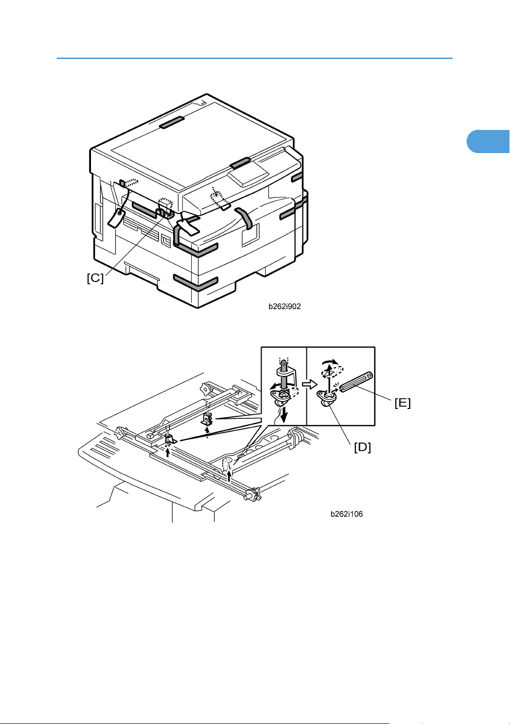
3. Remove the spacing wedge [C].
4. Remove the three scanner lock pins. (A tag is hanging from each pin.) To remove: Grasp the base of
the pin [D], turn the pin 90 degrees, and pull it down and out.
5. Remove the tags from the pins.
6. Break each pin off the base [D].
7. Discard the pin part [E].
8. Set each base [D] back into its original hole, turning it 90° to lock it into place. (Be sure to do this for
all three pins.)
Copier
17
1

9. Open the front door [F].
10. Lift lever [G], press in on latch [H] and pull the bottle holder [I] out. (You do not need to pull it completely
out of the machine.)
11. Take a new bottle of toner, and shake it several times.
12. Remove the outer cap [J].
• Do not remove the inner cap [K].
13. Load the bottle on the holder.
• Do not forcefully turn the toner bottle on the holder. After you turn on the main power switch, the
copier sets the bottle in place.
14. Push the bottle holder back into the machine.
15. Press the latch [L] down to lock the holder.
1. Installation
18
1

16. Remove the padding [M].
17. Pull each tabbed strip [N] out of the PCU with one hand, supporting the PCU with the other.
• Do not pull both strips at the same time, as this could damage the PCU.
18. Close the front door.
19. Pull out the paper tray, and remove the tape securing the end fence in the compartment.
20. Push the bottom plate down, and then load the paper.
21. Adjust the side fences. If you load paper shorter than A4, set the end fence in the correct position.
Copier
19
1
This manual suits for next models
4
Table of contents
Other Stella Bathroom Fixture manuals


Popular Bathroom Fixture manuals by other brands

OVE
OVE NOAH installation manual

Gessi
Gessi INGRANAGGIO 63801 manual

Hans Grohe
Hans Grohe Raindance 27471000 Instructions for use/assembly instructions

Spectrum Brands
Spectrum Brands Pfister Verano F-042-VR Quick installation guide

Franke
Franke F5 F5SM2014 Installation and operating instructions

Moen
Moen 8413 Series manual


Hans Grohe
Hans Grohe Talis Puro Showerpipe 27136000 Instructions for use

KEUCO
KEUCO Plan S Mounting instruction

Signature Hardware
Signature Hardware SIMPLE SELECT 948975 quick start guide

DittNyeBad
DittNyeBad WG-U881 R installation instructions

TECE
TECE TECEplanus Programming Instruction

Allen + Roth
Allen + Roth Roveland 2026VA-30-200-901 manual