Before installation, ensure that the equipment is complete and intact. Otherwise,
electrics shocks or fire may occur.
Do not connect or disconnect power cables when battery is power-on .
Ensure the cables are terminated with the correct polarity. Failure to do so may
result in electric arcs and cause may cause fire and/or personal injury.
Do not connect the batteries in series with different products.
Do not connect the battery directly to an AC power source.
Do connect the battery directly to the PV modules or PV array.
Do not connect batteries in parallel.
Do not connect the battery to a faulty and/or a non Solplanet inverter.
Do not create short circuits across the positive and negative terminals.
Ensure the grid is cut off and the battery is powered off before maintenance.
Ensure the earth cable is securely connected before operation.
Ensure the battery is installed in a dry and well-ventilated location.
The installation position must be away from direct sunlight and rain.
The installation position must be far away from potential sources of fire..
The installation position must be far away from all sources of water.
Do not install the equipment in locations that contain flammable gases and/or
flammable liquids.
The operation and service life of the battery depends on the operating temperature.
Operate the battery at a temperature equal to or better than the ambient temperature.
The recommended operating temperature range is from 0°C to 30°C.
Please use appropriately insulated tools for installation and maintenance.
Please check the LED status when the battery is powered on.
Please ensure the communication cable is connected correctly between the battery
and the inverter.
Please check for inverter alarms and the SOC reading once communication is
established between the inverter and the battery.
Recharge battery in every six months if not in use.
Recharge battery within 10 days after battery is fully discharged(SOC=0%).
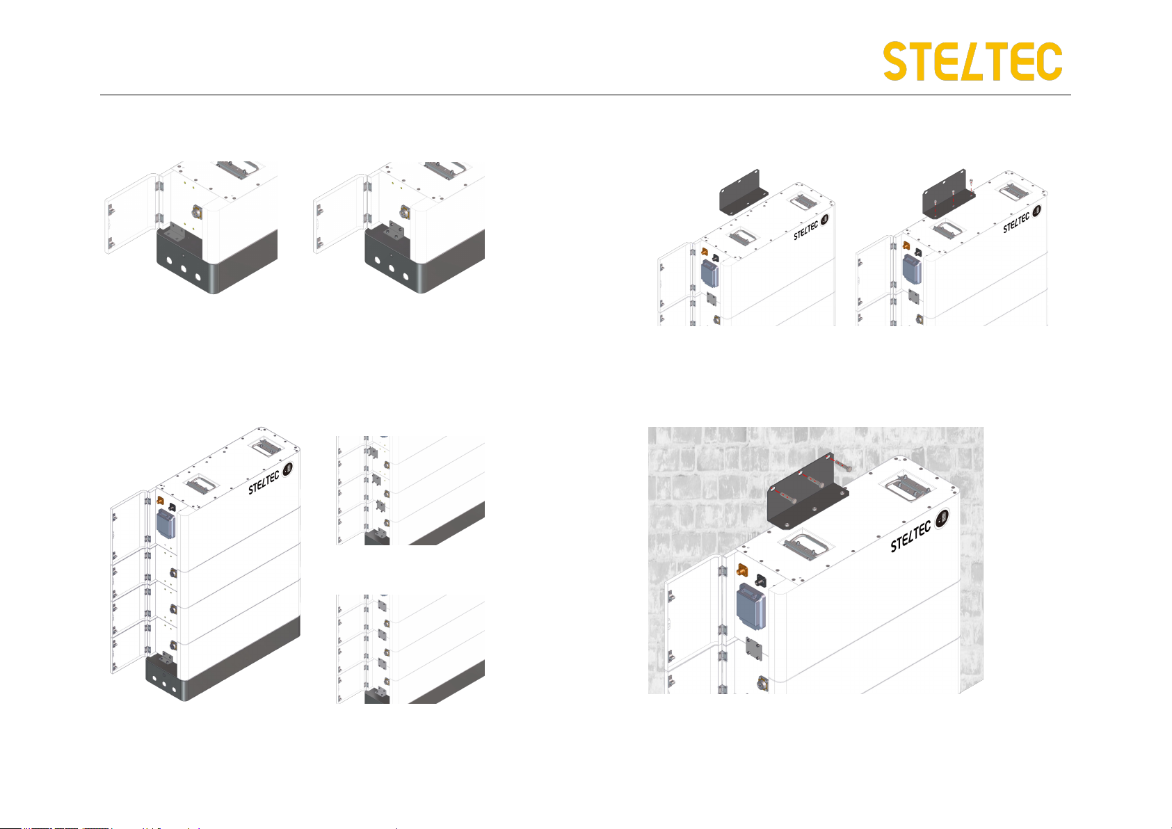
Ensure battery cable is installed correctly.
When the battery is being installed or repaired, ensure the battery is
powered off and and isolated. Using a multimeter check to ensure there is no
voltage in the positive and negative terminals.
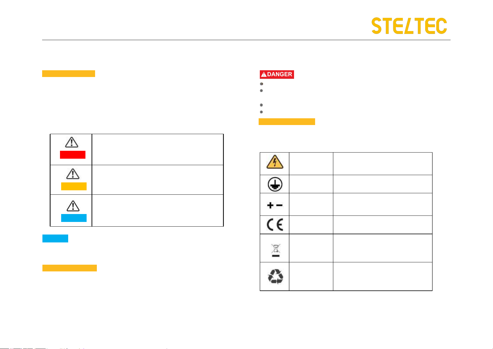
The products have passed UN38.3 certification.
The products have MSDS documents available.
• The products belong to class 9 dangerous goods.
Please protect the packing case from the below situations:
• Being dampened by rains, snows, or falling into water.
• Falling down or mechanical impact.
• Being upside-down or tilted.
2.4 Transportation Safety
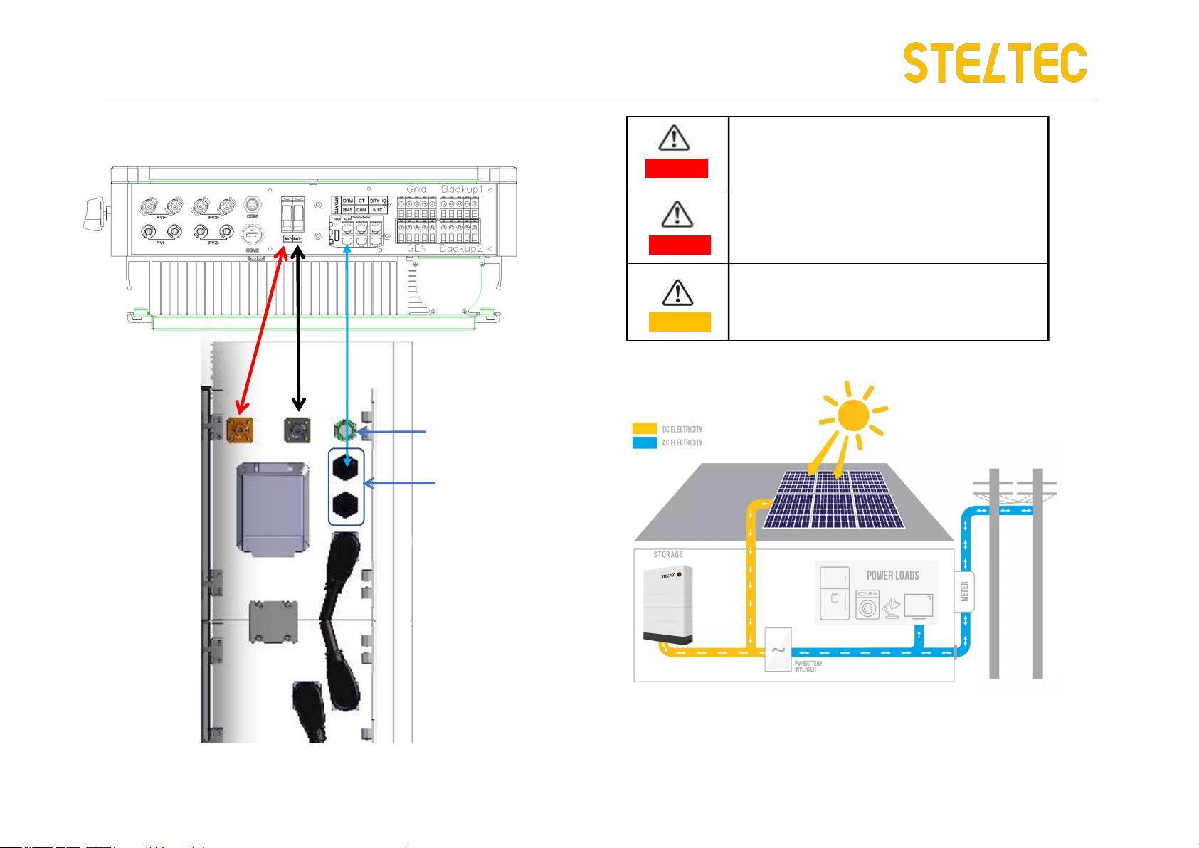
Environment Safety
Electrical Safety
Shanghai Steltec Energy Technology CO.,LTD
5/26 6/26


 user guide")