Stentorfield Profile User manual
OPERATOR’S MANUAL
Part No. PR09682000 Issue 2 02/02
Profile & Contour®
Profile & Contour®
OPERATOR’S MANUAL


Contents
Page No.
Introduction ...................................................................................................2
Important Safeguards ...................................................................................2
Features...........................................................................................................3
Specifications..................................................................................................4
External Features..........................................................................................5
Internal Features ...........................................................................................6
Installation Procedure..................................................................................7
Connecting the Water Supply....................................................................8
Connecting the Electricity Supply.............................................................8
Setting Up.......................................................................................................9
How to Vend a Drink ................................................................................11
Daily Cleaning and Re-filling.....................................................................12
Coffee Brewer Maintenance ....................................................................17
Tea Pot Brewer Cleaning ..........................................................................18
Operator Functions ...................................................................................19
Problem Solving ..........................................................................................30
De-commissioning the Machine..............................................................31
Recommended Spares List .......................................................................32
The following symbol is used throughout this Operator’s Manual:
Safety First! Take care, risk of personal injury.
©Copyright 2002 Crane Merchandising Systems
1
Operator’s Manual

Introduction
This manual provides a guide to the daily operation, basic cleaning and maintenance
tasks and operator accessible programming functions of the Profile and Contour®
range of table-top vending machines and indicates when the operator should call a
qualified service engineer for assistance.
Important Safeguards
When using the machine, always have this manual available for quick and easy reference
and always follow these basic safety precautions:
1. Read all instructions before using the machine and ensure that anyone who will
be involved with the cleaning or refilling of the machine also reads the
instructions.
2. The machine should be situated on a strong horizontal surface, at a convenient
height and in a position where it is not likely to be knocked off.
3. The mains lead should never trail from the machine and should always be kept
away from hot surfaces and sharp edges.
4. Do not operate the machine if any part is damaged, e.g. mains lead, until it has
been checked by a qualified Service Technician.
5. Allow the machine to cool before handling or moving.
6. Never immerse the machine in water, or any other liquid and never clean it with
a water jet.
7. If the machine should accidentally freeze up, call a Service Technician to check it
before switching on.
8. Ensure that you are conversant with the‘Health and Safety atWork and Electricity
at Work Regulations 1989’.
ALWAYS DISCONNECT THE MACHINE FROM THE MAINS ELECTRICITY
SUPPLY BEFORE CLEANING AND SERVICING.
This machine is for indoor use only and because it is a food machine, should be sited
in a clean, hygienic area.
It is recommended that this equipment is serviced by a trained Service Technician.
2
Operator’s Manual

Features
The Stentorfield Profile and Contour®table-top machines from Crane Merchandising
Systems, offer a complete range of hot drinks including Freshbrew Tea and Coffee,
Decaffeinated Coffee, Cappuccino, Espresso and Chocolate.
The LCD display, which provides information regarding selection and pricing, enables
the user to obtain a drink easily and quickly.
The Microprocessor Control System provides an automatic hot and cold flushing
facility, fault condition messages and a key operated jug facility, ensuring complete
reliability and flexibility.
Up to twelve independent drink prices are available. Alternative prices and free vend
periods are available on all selections.
Full cost control is maintained via the audit facility. This provides precise information
on drink counts and ingredients used.
It is the policy of Crane Merchandising Systems to continue developing its range of
beverage equipment.The information presented within this document is for information
only and may be changed without prior notice.
Crane Merchandising Systems accepts no responsibility for damage caused to the
equipment through misinterpretation or misuse of the information contained in this
manual.
3
Operator’s Manual

Specifications
* An external fitment is required to enable the Profile machine to support cashless operation
All weights and dimensions are approximate and are for guidance only.
Water Filter - External Fitment (where fitted)
The machine may be fitted with either an Everpure or Brita filter head and filter
cartridge. This unit will be located either within the machines base cabinet (where
applicable) or in the water supply line.
To maintain optimum drink quality, the cartridge should be replaced every six months
or earlier, depending upon the number of vends.
4
Operator’s Manual
Profile Contour
Height 985 mm 985 mm
Depth 590 mm 590 mm
Width 540 mm 660 mm
Weight 105 kg 184 kg
Electrical Services
(i) Voltage 220 - 240 Volts AC
(ii) Current 13 Amp Fused
(iii) Frequency 50 Hz
Water Services
(i) Pressure 100 Kpa (1 Bar) - 800 Kpa (8 Bar)
(ii) Stopcock 15 mm BSP from rising main
Cup Capacity 350 (when using 7oz squat cups)
Cup Type 7oz squat, 7oz tall and 9oz tall versions of the HIPS vending cup
may be used although modification to the machine will be
required to change between cup types
Coin Mechanism Coin mechanisms and cashless card systems*
can be fitted on request

External Features
Note: Illustration shows the Contour.
Key:
5
Operator’s Manual
1
2
3
4
5
6
7
8
9
1. Door
2. Door Lock
3. Cup Stand
4. Drip Tray
5. Selection Decals
6. Coin Entry (where fitted).
7. LCD Display
8. Keypad
9. Coin Return (where fitted)

Internal Features
Note: Illustration shows Contour interior.
Key:
6
Operator’s Manual
1
2
3
4
5
6
7
8
9
10
11 12
1. Coffee Canister (Freshbrew
machines only)
2. Coffee Brewer (Freshbrew machines
only)
3. Tea Brewer (Freshbrew Contour
machines only)
4. Large Freshbrew Waste Bucket
5. Small Freshbrew Waste Bucket
6. Drip Tray Grill
7. Mixing System
8. Cup Turret
9. Large Ingredient Canister
10. Door Switch
11. Filter Paper Roll (Freshbrew
machines only)
12. Small Ingredient Canister

Installation Procedure
Important!
It is essential that personnel responsible for installing, commissioning and servicing the
machine understand the following:
1. The installation and commissioning of the machine should only be carried out by
trained and authorised service engineers.
2. All water and electrical services must be correctly and safely connected.
3. All covers should be replaced correctly and securely and the machine left in a safe
condition.
4. The machine is suitable for indoor use only, sited in an area with a recommended
ambient temperature not below 10ºC and not exceeding 30ºC.
5. Prior to moving the machine to its location, ensure that there is sufficient access
space available via passageways, stairs, lifts,etc and that the table/counter where the
machine is to be located is strong enough to safely support its weight. (Refer to
Specifications Table).
6. The machine should be located near the appropriate water and electrical services
as detailed in the specification table.
7. To ensure adequate ventilation, 100 - 150 mm (4 - 6 inches) clearance must be
allowed between the back of the cabinet and the wall.
8. Open the cabinet door. Remove all transit packing and the installation kit from the
machine. Check for visual signs of damage which may have occurred during transit.
9. If the machine is damaged or any parts are missing, you must contact the supplier
immediately.
10. Ensure that the machine is levelled in both front to back and side to side planes
using the adjustable levelling feet.
7
Operator’s Manual
Connecting the Water Supply
1. The machine should be situated within 1 metre of a drinking water supply from a
rising main, terminating with a W.R.C. approved 15mm compression stop tap.
2. The water supply should comply with both the Statutory Instrument No.1147 -
“Water, England and Wales”and The Water Supply (Water Quality) Regulations
1989.Water pressure at the stop tap must be within the limits 1 - 8 Bar (100 Kpa - 800
Kpa).
3. Connect the flexi-hose supplied with the machine to the stop tap ensuring that the seal
supplied is fitted correctly. Flush the system via the stop tap (several gallons) before
connecting the hose to the machine.
4. Connect the hose to the inlet valve located on the rear of the machine. Ensure that the
seal is correctly fitted.Ensure that all water supply fittings are tight.Turn on the stop tap
and check for leaks.
Connecting the Electricity Supply
Safety First! THE MACHINE MUST BE EARTHED. ON NO ACCOUNT
SHOULD IT BE EARTHED TO THE WATER SUPPLY PIPE
The machine must be connected to a 240 Volt 50Hz 13 amp fused switched socket
outlet, installed to the latest edition of the IEE regulations, using a 3 pin BS approved
13 amp fused plug.
Important: If the mains lead becomes damaged in any way it must be replaced by a
special lead available from the manufacturer.
8
Operator’s Manual

Setting Up
The following procedure must be carried out by a trained installation engineer before
the machine can be used for the first time.
1. Ensure that the electrical and water services to the machine are connected
correctly and turned on. Ensure that the waste tray is fitted correctly to the
machine.
2. Open the front door of the machine.Insert the safety key supplied with the machine
into the door switch.The machine is now on.
3. Whilst the boiler in the machine is filling, the display will show the message:
4. As the water in the boiler starts to heat, the message on the LCD will change to:
5. Ensure that no water overflows from the boiler tank overflow pipe into the waste
tray. Check the system for leaks.
Safety First! Should the machine fail to fill correctly or leak, turn off the
stopcock and contact the machine supplier for assistance.
6. Check the LCD display on the front of the machine to ensure that the water has
heated to the correct temperature and that the machine is in standby mode.The
display will show the message:
Where XX:XX is the current time.
7. Loading the cup turret. Swing the cup turret assembly out of the machine and
remove the lid. Fill the tubes with the correct size cups for the type of cup turret
fitted to the machine.
Important: Do not fill the tube directly above the cup dispense position. Allow
the cup turret to rotate a full tube to the cup dispense position. Rotating the cup
turret by hand will damage the mechanism.
9
Operator’s Manual
SORRY NOT IN USE
LOW WATER
SORRY NOT IN USE
WATER HEATING
PLEASE SELECT DRINK
TIME XX:XX

Allow the cups to drop into the tubes directly from the packaging. DO NOT
TOUCH THE CUPS WITH YOUR HANDS. Replace the cup turret lid.
8. Remove the ingredient canisters - DO NOT place ingredient canisters on the floor.
Remove the lids from the ingredient canisters. Fill the canisters with the correct
ingredients, re-fit the lids and re-fit canisters into machine.
9. Return the cup turret assembly to its operating position. Ensure that the unit locks
into place.
Freshbrew models only, proceed with steps 10 and 11
10. Remove the pin from the filter paper holder. Load the filter paper roll (provided in
the installation kit) onto the support. Replace the pin.
11. Press and release the paper feed switch, located in the switch panel on the rear
of the door,to operate the brewer.When the brewer chamber reaches its fully open
position, remove the safety key from the door switch to switch off the power to
the machine.
Remove the brewer cover. Carefully feed the filter paper under the raised chamber
and through the feed wheels. Refit the brewer cover.
Replace the safety key into the door switch to restore power to the machine.The
filter paper will index automatically and the brewer chamber will return to the
closed position.
Whilst this operation is taking place the display will show the message:
12. Press the cup test switch, located in the switch panel on the rear of the door, to
index the cup turret mechanism to the first available full cup stack. Ensure that the
cup drop mechanism operates correctly.
13. Operate the machine through its complete range of vends to ensure that each vend
is correctly dispensed. Place an empty cup under the dispense head for each
selection. Remove the safety key and close the cabinet door. Ensure that the
machine is left in a clean and safe condition.
10
Operator’s Manual
BREWER REPOSITIONING
PLEASE WAIT

11
Operator’s Manual
How To Vend A Drink
1. Insert sufficient credit to cover cost of drink
choice (where applicable).
Press the number combination on the keypad
for the drink of your choice followed by a
strength option if required.
2. Cup will drop into the cup catcher and dispense
head will move into dispense position.
The drink will now be delivered into the cup.
3. The dispense head returns to its parked
position and the display will tell you when your
drink is ready.
Remove the cup carefully from the cup catcher.
Press the coin return button situated next to
the coin entry to receive any change owed.
4. To vend a drink into your own cup, lower the
cup stand to horizontal position. Place your cup
on the stand.
Select a drink as described above. Press the *
(star) key before pressing the drink selection
number on the keypad.
Remove your cup and raise the cup stand into
its vertical position.

12
Operator’s Manual
Daily Cleaning and Re-filling
The quality of drinks produced by Profile and Contour®machines can only be
maintained if the machine is cleaned regularly following the schedule outlined. Before
carrying out the daily cleaning procedure described on the following pages, it is
recommended that you have the following materials to hand:
❍Bactericidal Cleaner
❍De-Staining Agent
❍Cleaning Cloths
❍Paper Towels
❍Small Brush
❍Two Large Buckets
❍Disposable Gloves
Bactericidal Cleaner
This can either be a liquid or powder agent which should be dissolved in clean water
in accordance with the instructions on the product packaging. The solution should be
used for cleaning machine components and wiping surfaces during the cleaning
operation.
De-Staining Agent
This is a liquid or powder agent which should be dissolved in clean water in accordance
with the instructions on the product packaging. The solution can be used on heavily
soiled or stained components such as buckets and drip trays. Items or surfaces cleaned
with this solution must be rinsed in clean water to remove traces of the cleaning agent.
Liquid Destainer - Brewer Units
Crane Merchandising Systems recommends that a liquid destaining product is used for
cleaning the brewer units fitted to Profile and Contour®machines.The product must
be user in accordance with the instructions on the product packaging, following all
health and safety guidelines. Detailed procedures for cleaning coffee and tea brewer
units fitted to the machines are outlined on pages 17 and 18 of this operator’s manual.
It is necessary to carry out the cleaning and maintenance procedure outlined on the
following pages on a regular basis, either at the end of the day or at the start of the
day before the machine is in constant use.
13
Operator’s Manual
1. On arrival at the machine, open the door. Fill a
cleaning bucket with hot water and dilute the
bactericidal cleaner in accordance with the
instructions on the product packaging.
Swing the cup turret assembly out of the machine
in order to gain access to the ingredient canisters.
Remove the ingredient canisters. DO NOT PLACE
THEM ON THE FLOOR.
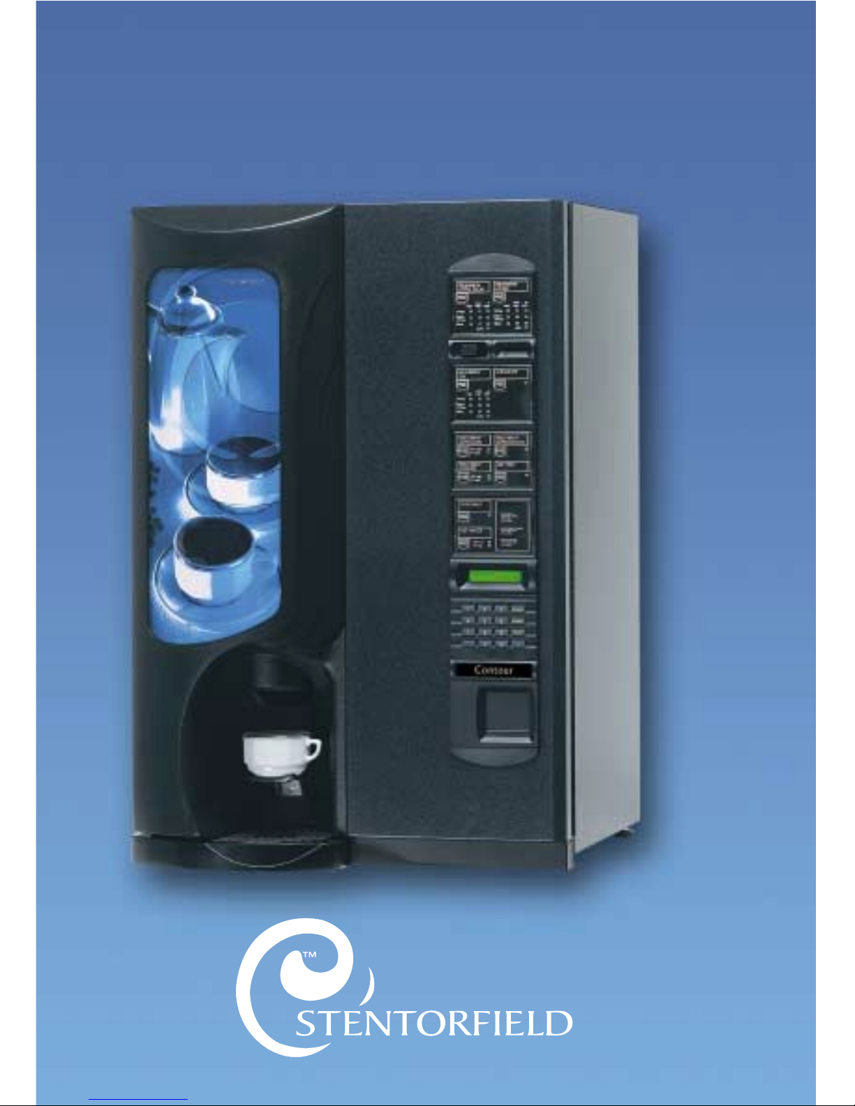
2. Remove the canister shelf and extract tray.
Using a dry brush, clean the area under the extract
tray.
Wipe the upper interior of the machine. Clean the
extract tray and refit into machine.
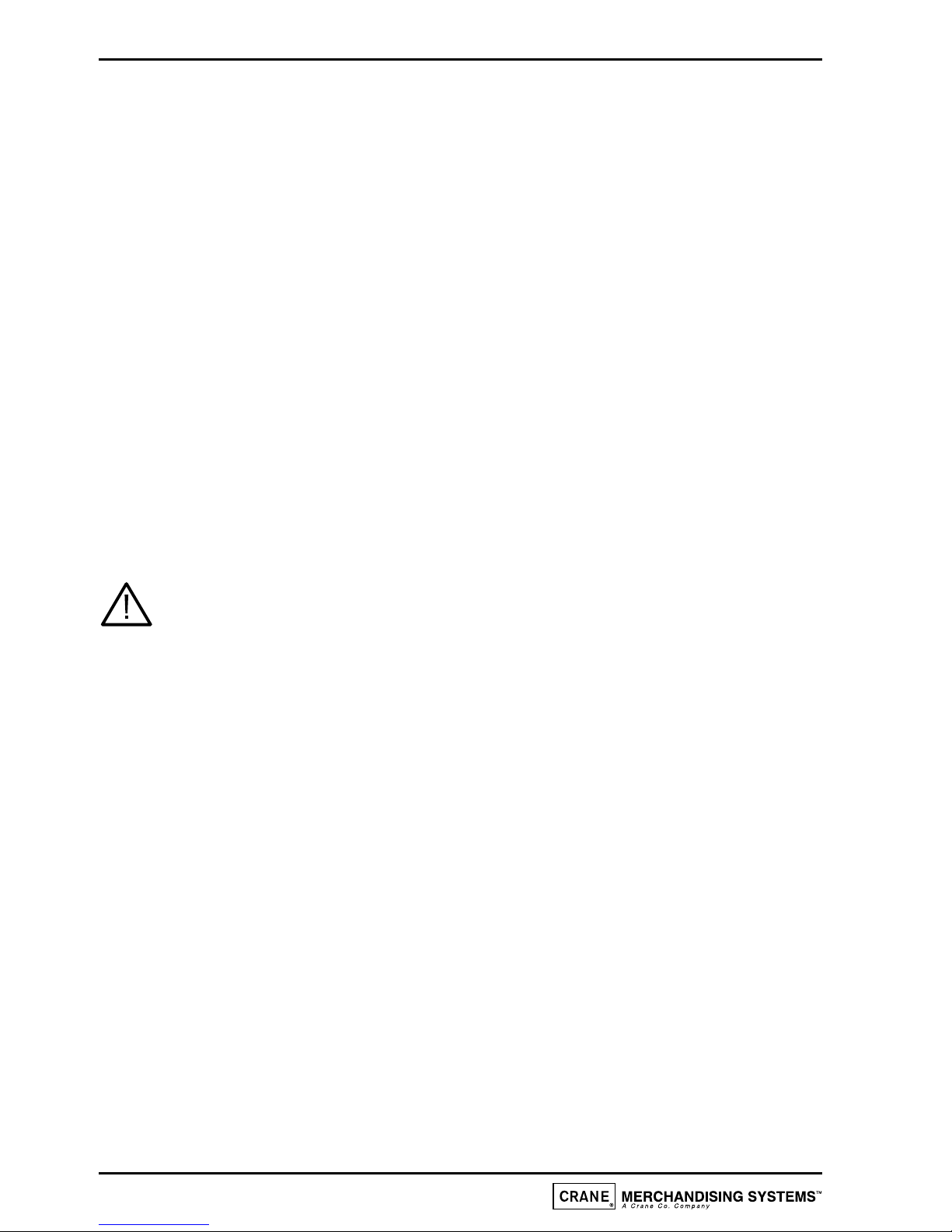
3. Remove steam hoods (a) and mixing bowls (b) from
whipper bases (c).
Remove the dispense pipes (d) from the whipper
bases (c) and the plastic dispense block.
Remove the plastic thumb-screw securing the
plastic dispense block to the dispense head
assembly. Remove the dispense block and clean
thoroughly with the mixing system components.
4. Remove the complete whipper unit (a),including the
whipper base as shown.
Split the whipper unit into separate parts - whipper
base, mixing chamber and impeller.
Clean all of the mixing parts, including the steam
hoods and mixing bowls thoroughly in the diluted
bactericidal cleaner solution.
Rinse all components with clean water and dry
thoroughly before refitting to machine.

14
Operator’s Manual
5. Refit the whipper bases (a). Rotate the base anti-
clockwise to lock into position as shown.
Refit the impeller's (b). Line up the dot on the
impeller with the flat on the motor shaft.
Refit mixing chambers, mixing bowls, steam hoods
and dispense pipes.
6. Refit the dispense pipes to mixing chamber outlets.
Refit the plastic dispense block to the dispense head
assembly. Secure with the plastic thumb screw (a).
Ensure that the dispense pipes are located into their
correct positions in the dispense block as shown in
the illustration.
7. With a damp sanitised cloth, remove any ingredient
on the exterior of the canisters, including any
product build-up around the canister outlets.
Check ingredient canisters and refill if required.
Refit the canisters into the machine from left to
right.Ensure that the canisters are refitted correctly.
Weekly: Empty and wash the ingredient canisters.
Dry thoroughly, refill and refit into machine.
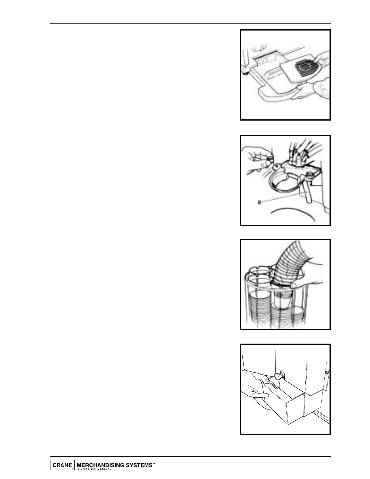
8. Remove the freshbrew waste bucket(s), where
fitted, from the machine.
Empty the contents, clean and refit to machine.
a
b
a
9. Remove the drip tray from the machine. Empty and
clean.
Clean around the cup station area with a damp
sanitised cloth.
Wipe down the interior of the door. Clean the base,
sides and back of the machine.
Replace the drip tray.
10. Undo the thumb screws and remove cup throat
complete with drain pipe (a).
Clean cup throat and pipe in the sanitiser solution.
Rinse components with clean water and dry
thoroughly.
Reassemble to machine ensuring that drain pipe is
correctly located through drain hole.
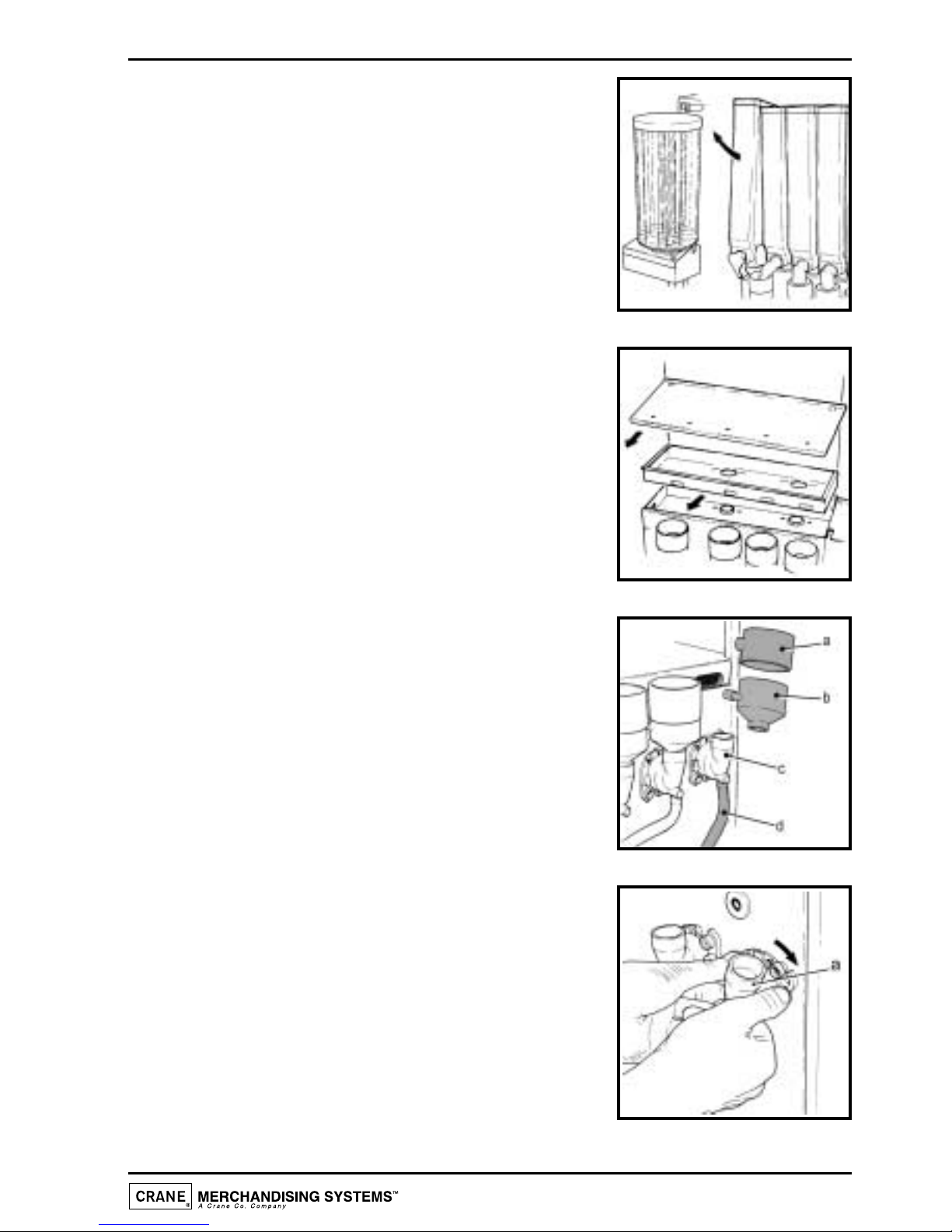
11. Check the levels of the cups in the cup stack.Where
necessary, remove the cup stack lid and fill.
Important: Do not fill the tube directly above the
cup dispense position.Allow the cup turret to rotate
a full tube to the cup dispense position.Rotating the
cup turret by hand will damage the mechanism.
DO NOT TOUCH THE CUPS WITH YOUR
HANDS.Allow the cups to drop into the cup stack
directly from the packaging. Replace lid.
12. Un-lock the cashbox (where fitted); remove and
empty.
Refit the cashbox to the machine, turning the lock
to secure.
15
Operator’s Manual

13. Remove the coin mechanism cover (where fitted).
Wipe the inside of the coin mechanism with a damp
cloth.
Check the coin tubes and refill as required.
14. Restore power to the machine using the safety key
as shown in the illustration.
Press the program entry switch, located in the
switch panel on the rear of the door and enter the
correct operator code - selection button 1 followed
by 7.
Proceed as follows:-
(i) Press the flush switch and check that all of the
mixing stations are water tight.
(ii) Using the
service switch, test vend each drink
selection.
(iii) Press the view counters switch and record
the audit information.
Remove the safety key and close the door.
Clean and buff the outside of the machine.
16
Operator’s Manual
Coffee Brewer Unit Maintenance
At least twice a week the coffee brewer unit must be removed from freshbrew
machines and cleaned.
Safety First! Never clean or service the brewer unit while it is in motion as
fingers may become trapped in the mechanism.
Referring to the diagram, proceed as follows:-
1. Open the front door of the machine. Remove the
paper/waste ingredient guard.
2. Switch on the power using the door switch safety
key.
3. Press and release the paper feed switch to index
the brewer to its fully open position.
4. When the brewer reaches its fully open position,
remove the safety key to switch off the power.
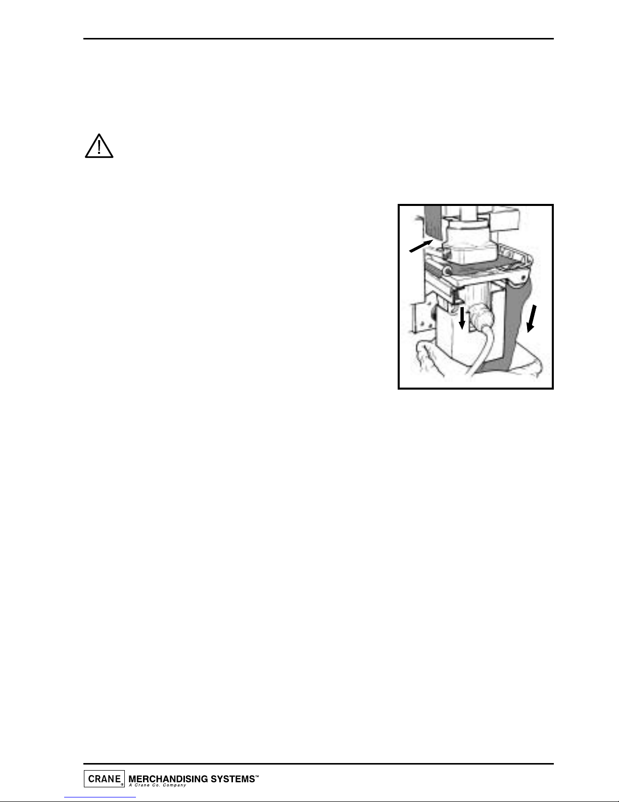
5. Tear the filter paper above the brewer (a).Remove
the used paper from the brewer unit.
6. Remove the brewer dispense pipe from the dispense head.
7. Pull down the brewer release pin (b) and carefully lift the brewer unit up and clear
of its locating bracket.Thoroughly clean the external surfaces of the brewer.
8. With the brewer unit removed from the machine, clean the area surrounding its
locating bracket.Refit brewer to machine and refit the outlet pipe to the dispense
head.
9. Switch on the power using the door switch safety key.The brewer chamber will
return to its closed position.
10. Pour 2-3 full cap measures of de-staining fluid directly into the top of the brewer
chamber. Flush the brewer using the brewer flush facility a minimum 4 times.
11. Press and release the paper feed switch to index the brewer to its fully open
position. Remove the door switch safety key to switch off the power to the
machine.
12. Feed the filter paper through the paper feed mechanism. Switch on the power to
the machine using the safety key. Filter paper will index automatically and the
brewer chamber will return to its closed position. Refit brewer guard.
13. Remove the brewer waste bucket and empty the contents. Clean waste bucket
and refit. Remove the safety key and close the door.
17
Operator’s Manual
a
b
Tea Pot Brewer Cleaning
At the same time as the coffee brewer is being cleaned, the tea brewer (where fitted)
should also be removed and cleaned.
Safety First! Never clean or service the tea pot brewer unit while it is in
motion as fingers may become trapped in the mechanism.
Referring to the illustrations, proceed as follows:-
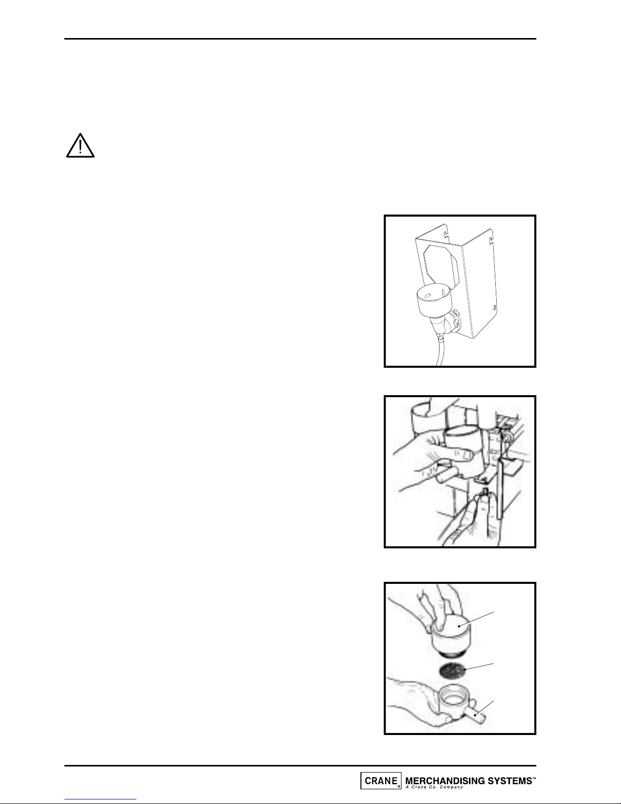
1. Remove the tea pot bowl and mounting bracket
assembly from the machine.
Clean all parts of the tea pot bowl assembly and
mounting bracket using the liquid destaining agent.
Follow the instructions for soak cleaning on the
product packaging.
Rinse all components with clean water and dry
thoroughly.
2. Undo the thumb screw retaining the brewer unit.
Remove the complete brewer unit from the
machine as shown.
3. Split the brewer unit into its separate parts as
shown.
Clean bowl (a), gauze (b) and outlet (c) using the
liquid destaining agent. Follow the instructions for
soak cleaning on the product packaging.
Rinse all components in clean water, dry
thoroughly and refit to machine.
Re-fit tea pot bowl/mounting bracket assembly.
18
Operator’s Manual
a
b
c
This manual suits for next models
1
Table of contents
Other Stentorfield Coffee Maker manuals


Popular Coffee Maker manuals by other brands

Bloomfield
Bloomfield 9003 owner's manual

Schaerer
Schaerer Coffee Art TouchIT Programming manual

Saeco
Saeco 10000241 Operating and maintenance manual

Hamilton Beach
Hamilton Beach Fresh Grind manual

Scanomat
Scanomat Classic Brew manual

Magic Capppuccino RS
Magic Capppuccino RS SIN 017R operating instructions

Russell Hobbs
Russell Hobbs 10968S instructions

Bosch
Bosch TASSIMO style TAS110 Series user manual

N&W Global Vending
N&W Global Vending Kobalto Installation operation & maintenance

Kenwood
Kenwood CM300 series instructions

Graef
Graef ESM 802 operating instructions

Marco
Marco OTTOMATIC Instructional Brochure


