Stentorfield Vision Xtra User manual

Part No. PR07370000 New 06/03
Vision Xtra
Operators Manual
Vision Xtra
Operators Manual


Contents
Page No.
Introduction ...................................................................................................2
Important Safeguards ...................................................................................2
Features...........................................................................................................3
Specifications..................................................................................................4
External Features..........................................................................................5
Internal Features ...........................................................................................6
Installation Procedure..................................................................................7
Connecting the Water Supply....................................................................8
Connecting the Electricity Supply.............................................................8
Setting Up.......................................................................................................9
How To Vend A Drink................................................................................10
Daily Cleaning and Re-filling.....................................................................11
Operator Functions ...................................................................................14
Problem Solving ..........................................................................................24
Recommended Spares List.......................................................................25
De-commissioning the Machine..............................................................26
The following symbol is used throughout this Operator’s Manual:
Safety First! Take care, risk of personal injury.
©Copyright 2003 Crane Merchandising Systems
1
Operator’s Manual

Introduction
This manual provides a guide to the installation, daily operation, basic cleaning and
maintenance tasks and operator accessible programming functions of the Vision Xtra
range of table-top beverage systems and indicates when the operator should call a
qualified service engineer for assistance.
Important Safeguards
When using the machine, always have this manual available for quick and easy reference
and always follow these basic safety precautions:
1. Read all instructions before using the machine and ensure that anyone who will
be involved with the cleaning or refilling of the machine also reads the
instructions.
2. The machine should be situated on a strong horizontal surface, at a convenient
height and in a position where it is not likely to be knocked off.
3. The mains lead should never trail from the machine and should always be kept
away from hot surfaces and sharp edges.
4. Do not operate the machine if any part is damaged, e.g. mains lead, until it has
been checked by a qualified Service Technician.
5. Allow the machine to cool before handling or moving.
6. Never immerse the machine in water, or any other liquid and never clean it with
a water jet.
7. If the machine should accidentally freeze up, call a Service Technician to check it
before switching on.
8. Ensure that you are conversant with the‘Health and Safety atWork and Electricity
at Work Regulations 1989’.
ALWAYS DISCONNECT THE MACHINE FROM THE MAINS ELECTRICITY
SUPPLY BEFORE CLEANING AND SERVICING.
This machine is for indoor use only and because it is a food machine, should be sited
in a clean, hygienic area.
It is recommended that this equipment is serviced by a trained Service Technician.
2
Operator’s Manual

Features
Vision Xtra table-top beverage systems offer customers a complete range of high
quality drinks including Coffee, Cappuccino, Caffe Mocha, Espresso, Chocolate and Tea.
The two models available provide customers with a comprehensive drinks choice of
either 9 or 11 selections.
Outstanding build quality and proven reliability are inherent in Vision Xtra beverage
systems and when combined with quality ingredients, good service and filtered water,
they provide high quality drinks and satisfied customers.
The choice of drinks available from the Vision Xtra is unlimited,even drinks containing
sugar can be dispensed. Every selection button is configurable to any mix of the
ingredient canisters, developing any drinks combination to suit customers’needs in a
choice of cup, mug or jug size.
Optimised drinks presentation is achieved through control of the whipping time within
the drink mixing cycle enhancing the drink quality even further.
The LCD display, which provides information regarding selection and pricing, enables
the user to obtain a drink easily and quickly.
The Microprocessor Control System provides fault condition messages and a jug facility,
ensuring complete reliability and flexibility.
Full cost control is maintained via the audit facility.This provides precise information
on drink counts and ingredients used.
It is the policy of Crane Merchandising Systems to continue developing its range of
beverage equipment.The information presented within this document is for information
only and may be changed without prior notice.
Crane Merchandising Systems accepts no responsibility for damage caused to the
equipment through misinterpretation or misuse of the information contained in this
manual.
3
Operator’s Manual

Specifications
All weights and dimensions are approximate and are for guidance only.
4
Operator’s Manual
Vision 300 Vision 400
Height 680 mm 680 mm
Depth 487 mm 487 mm
Width 295 mm 380 mm
Weight 35 kg 50 kg
Boiler Capacity 5.5 Litres 7 Litres
Number of Canisters 3 4
Water Services
(i) Pressure 100 Kpa (1 Bar) - 800 Kpa (8 Bar)
(ii) Stopcock 15 mm BSP from rising main
Electrical Services Vision 300 Vision 400
Voltage 220 - 240 AC or 220 - 240 AC or
415 Volts 3 Phase 415 volts 3 Phase
Current (2.47kW Heater) 13 Amp Single Phase 13 Amp Single Phase
Current (4.85kW Heater) 30 Amp Single Phase 30 Amp Single Phase
Current (7.30kW Heater) 415Volts 3 Phase 415Volts 3 Phase
Frequency 50Hz 50Hz
Optional Extras Vision 300 Vision 400
Std. Jug Extension
Height 75 mm 75 mm
Weight 3 kg 5 kg
Tall Jug Extension
Height 140 mm 140 mm
Weight 6 kg 8 kg
Coin/Card Module
Width 190 mm 190 mm
Weight 8 kg 8 kg
Condiments Unit
Height 704 mm 704 mm
Width 316 mm 316 mm
Depth 467 mm 467 mm
Base Cabinets Height Width Depth
Standard 900 mm 457 mm 533 mm
With Side Shelf 900 mm 770 mm 533 mm
Vision 300 + Coin Module 900 mm 573 mm 650 mm
Vision 400 + Coin Module 900 mm 700 mm 650 mm
Vision 300/400 and 900 mm 573 mm 650 mm
Condiment Unit

External Features
Note: Illustration shows Vision 400 with optional jug extension and coin pod.
Key:
5
Operator’s Manual
1. LCD Display
2. Door
3. Keypad
4. Door Lock
5. Cup Stand - Optional
6. Jug Extension - Optional
7. Drip Tray
8. Drip Tray Grill
9. Coin Return - Coin Pod
10. Door Lock - Coin Pod
11. Selection Decals - Coin Pod
12. Coin Reject Button - Coin Pod
13. Coin Entry - Coin Pod

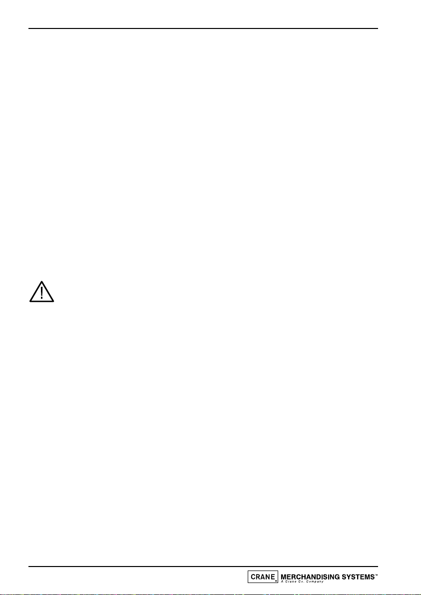
Internal Features
Note: Illustration shows Vision 400.
Key:
6
Operator’s Manual
OFF
ON
4
6
5
1
2
3
4 3 2 1
1. Ingredient Canister
2. Canister Chute
3. Mixing Stations
4. Dispense Spout
5. Main Loom
6. Function Switches

Installation Procedure
Important!
It is essential that personnel responsible for installing, commissioning and servicing the
machine understand the following:
1. The installation and commissioning of the machine should only be carried out by
trained and authorised service engineers.
2. All water and electrical services must be correctly and safely connected.
3. All covers should be replaced correctly and securely and the machine left in a safe
condition.
4. The machine is suitable for indoor use only, sited in an area with a recommended
ambient temperature not below 10ºC and not exceeding 30ºC.
5. Prior to moving the machine to its location, ensure that there is sufficient access
space available via passageways, stairs, lifts,etc and that the table/counter where the
machine is to be located is strong enough to safely support its weight. (Refer to
Specifications Table).
6. The machine should be located near the appropriate water and electrical services
as detailed in the specification table.
7. To ensure adequate ventilation, 100 - 150 mm (4 - 6 inches) clearance must be
allowed between the back of the cabinet and the wall.
8. Open the cabinet door. Remove all transit packing and the installation kit from the
machine. Check for visual signs of damage which may have occurred during transit.
9. If the machine is damaged or any parts are missing, you must contact the supplier
immediately.
10. Ensure that the machine is levelled in both front to back and side to side planes
using the adjustable levelling feet.
7
Operator’s Manual
Connecting the Water Supply
1. The machine should be situated within 1 metre of a drinking water supply from a
rising main, terminating with a W.R.C. approved 15mm compression stop-tap.
2. The water supply should comply with both the Statutory Instrument No.1147 -
“Water, England and Wales”and The Water Supply (Water Quality) Regulations
1989.Water pressure at the stop-tap must be within the limits 1 - 8 Bar (100 Kpa - 800
Kpa).
3. Connect the flexi-hose supplied with the machine to the stopcock ensuring that the
seal supplied is fitted correctly. Flush the system (several gallons) before connecting the
machine.
4. Connect the hose to the inlet valve located on the rear of the machine. Ensure that the
seal is correctly fitted. Ensure that all water supply fittings are tight.Turn on the stop-
tap and check for leaks.
Connecting the Electricity Supply
Safety First! THE MACHINE MUST BE EARTHED. ON NO ACCOUNT
SHOULD IT BE EARTHED TO THE WATER SUPPLY PIPE
13 Amp Single Phase - The machine is fitted with 1 x 2.4kW heating element and
requires a 230V 50Hz, 13 amp fused switched socket outlet, installed to the latest
edition of the IEE regulations, within 1 metre of the machine.
30 Amp Single Phase - The machine is fitted with 2 x 2.4kW heating elements,
4.8kW in total and requires a 230V 50Hz, 30 amp fused switched cord outlet spur box,
installed to the latest edition of the IEE regulations, within 1 metre of the machine.
415 Volts, 3 Phase - The machine is fitted with 3 x 2.4kW heating elements, 7.2kW
in total and requires a 415V 50Hz, 3 phase isolator fused at 15 amps per phase,installed
to the latest edition of the IEE regulations, within 1 metre of the machine.
Note: If the mains lead becomes damaged in any way it must be replaced by a special
lead available from the manufacturer.
8
Operator’s Manual

Setting Up
The following procedure must be carried out by a trained installation engineer before
the machine can be used for the first time.
1. Ensure that the electrical and water services to the machine are connected
correctly and turned on. Ensure that the waste tray is fitted correctly to the
machine.
2. Open the front door of the machine. Switch the machine on using the electronics
on/off switch located in the switch panel to the right of the ingredient canisters.
3. Whilst the boiler in the machine is filling and heating the water,the display will show
the message:
4. Ensure that no water overflows from the boiler tank overflow pipe into the waste
tray. Check the system for leaks.
Safety First! Should the machine fail to fill correctly or leak, turn off the
stopcock and contact the machine supplier for assistance.
5. Check the LCD display on the front of the machine to ensure that the water has
heated to the correct temperature and that the machine is in standby mode.The
display will show the message:
Where XX:XX is the current time.
6. Remove the ingredient canisters - DO NOT place ingredient canisters on the floor.
7. Fill the ingredient canisters with the correct ingredients.
Note: Canister 3 must always be filled with coffee ingredient (refer to the
illustration on page 6)
Re-fit the ingredient canisters into the machine.
8. Operate the machine through its complete range of vends to ensure that each vend
is correctly dispensed. Place an empty cup under the dispense head for each
selection. Close the cabinet door. Ensure that the machine is left in a clean and safe
condition.
9
Operator’s Manual
SORRY NOT IN USE
WATER HEATING
PLEASE SELECT DRINK
TIME XX:XX

How To Vend A Drink
1. Place your cup/mug on the drip tray grille under
the dispense head.
2. Press the selection button for the drink of your
choice.
The drink will now be delivered into the
cup/mug.
3. The display will tell you when your drink is
ready.
Remove the cup/mug and add milk etc as
required.
4. For jug vends, lift up the cup stand (if fitted) and
place the jug on the grille under the dispense
head.
Press the coffee-jug selection button.The drink
will be delivered into the jug. Press the stop-jug
button to stop the vend.
Remove jug and lower the cup stand to
horizontal position.
10
Operator’s Manual

Daily Cleaning and Re-filling
The quality of drinks produced by the Vision Xtra can only be maintained if it is
cleaned regularly following the schedule outlined.Before carrying out the daily cleaning
procedure described on the following pages, it is recommended that you have the
following materials to hand:
❍Bactericidal Cleaner
❍De-Staining Agent
❍Cleaning Cloths
❍Paper Towels
❍Small Brush
❍Two Large Buckets
❍Disposable Gloves
Bactericidal Cleaner
This can either be a liquid or powder agent which should be dissolved in clean water
in accordance with the instructions on the product packaging. The solution should be
used for cleaning machine components and wiping surfaces during the cleaning
operation.
De-Staining Agent
This is a liquid or powder agent which should be dissolved in clean water in accordance
with the instructions on the product packaging.The solution can be used on heavily
soiled or stained components such as buckets and drip trays. Items or surfaces cleaned
with this solution must be rinsed in clean water to remove traces of the cleaning agent.
It is necessary to carry out the cleaning and maintenance procedure outlined on the
following pages on a regular basis, either at the end of the day or at the start of the
day before the machine is in constant use.
The following procedures must be carried out every day:
❍Checking/re-filling product canisters
❍Dismantling and cleaning the mixing system
❍Emptying and cleaning the waste tray
11
Operator’s Manual
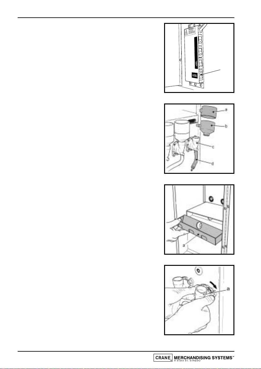
1. On arrival at the machine, open the door and switch
off the electronics on/off switch (a) located to the
right of the ingredient canisters.
Remove the ingredient canisters. DO NOT PLACE
THEM ON THE FLOOR.
Fill a cleaning bucket with hot water.With a damp
sanitised cloth, remove any ingredient on the
exterior of the canisters, including any product
build-up around the canister outlets.
2. Remove steam hoods (a) and mixing bowls (b) from
whipper bases (c).
Remove dispense pipes and spouts (d) from the
dispense head and whipper bases (c).
Remove and clean the dispense head block.
Refit dispense head block to machine.
3. Remove the extract tray (a). Using a dry brush, clean
the area under the extract tray.
Wipe the upper interior of the machine. Clean the
extract tray and refit into machine.
Check ingredient canisters and refill if required.Refit
into machine.
Weekly: Empty and wash the ingredient canisters.
Dry thoroughly, refill and refit into machine.
4. Remove the complete whipper unit (a),including the
whipper base as shown.
Split the whipper unit into separate parts - whipper
base, mixing chamber and impeller.
Clean all of the mixing parts thoroughly in the
diluted bactericidal cleaner solution.
Rinse all components with clean water and dry
thoroughly before refitting to machine.
12
Operator’s Manual
VIEW
COUNTERS
FLUSH
1
2
3
a
a
b
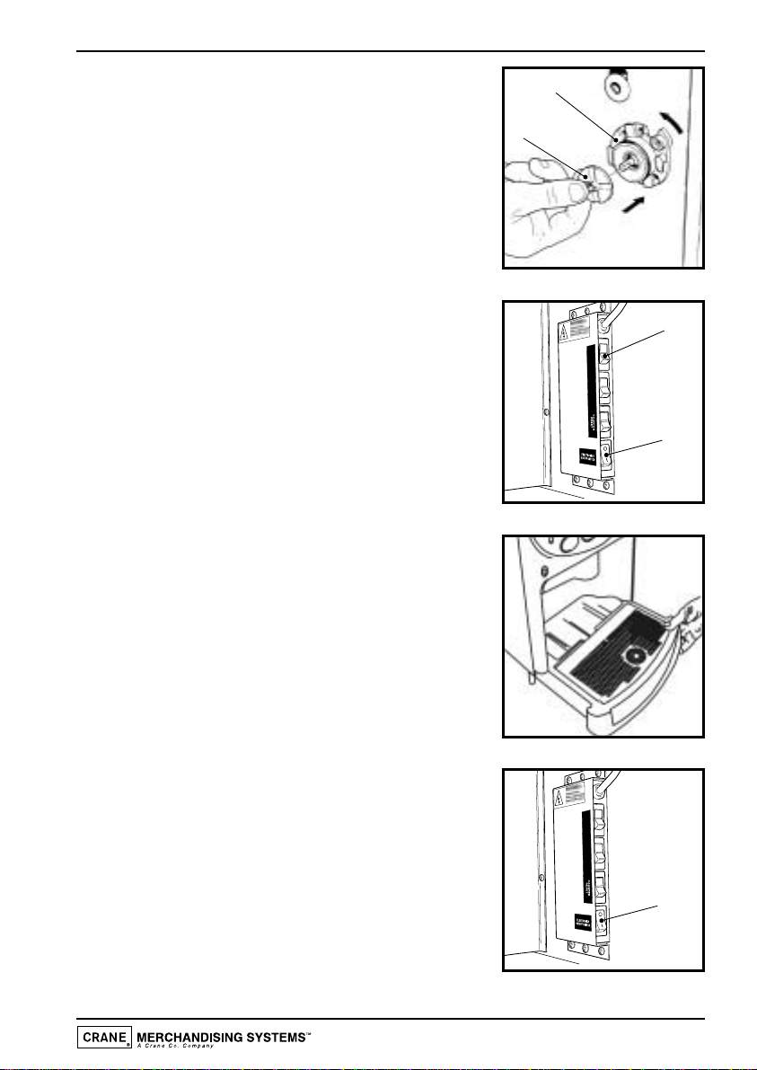
5. Refit the whipper bases (a). Rotate the base anti-
clockwise to lock into position as shown.
Refit the impeller's (b). Line up the dot on the
impeller with the flat on the motor shaft.
Refit mixing chambers, mixing bowls, steam hoods
and dispense pipes.
6. Switch on the electronics on/off switch (a) located
to the right of the ingredient canisters.
Ensure that the mixing system has been refitted
correctly. Proceed as follows:-
(i) With the machine in stand-by mode, press the
flush switch (b).
(ii) The machine will now flush the mixing system.
7. Carefully remove the waste tray from the machine.
Remove the waste tray grill and empty the contents
of the tray.Wash the tray and grill thoroughly and
where necessary, sanitise using the diluted
bactericidal cleaner solution.
Dry both components using a clean, dry cloth.
Reassemble the waste tray and grill and refit to the
machine.
8. Switch off the electronics on/off switch (a).This will
disable the keypad.
Wipe down the interior of the door. Clean the base,
sides and rear of the machine.
With a dry cloth buff the exterior of the machine.
After cleaning, switch on the electronics on/off
switch, close the door and test vend each drink
selection using an empty cup for each vend.
13
Operator’s Manual
VIEW
COUNTERS
FLUSH
1
2
3
a
b
VIEW
COUNTERS
FLUSH
1
2
3
a
Operator Functions
The machine features the following operator functions:
1. Flush system
2. View counters
3. Clear counters
4. Set current time and date, pricing, price periods
5. Electronics on/off
The Flush system function and the View counters function are accessible via
function switches inside the machine. Other functions accessible by the operator are
special functions that result in data being changed.To safeguard the stored data, the
operator accesses a Programming mode which is protected with an Operator’s
Access Code.
Programming Mode
To access the Programming mode you need to enter a sequence of key strokes on the
front panel.The time between each key stroke must be less than 5 seconds otherwise
the machine will return to standby mode. Once in Programming mode, there is no time
constraint.
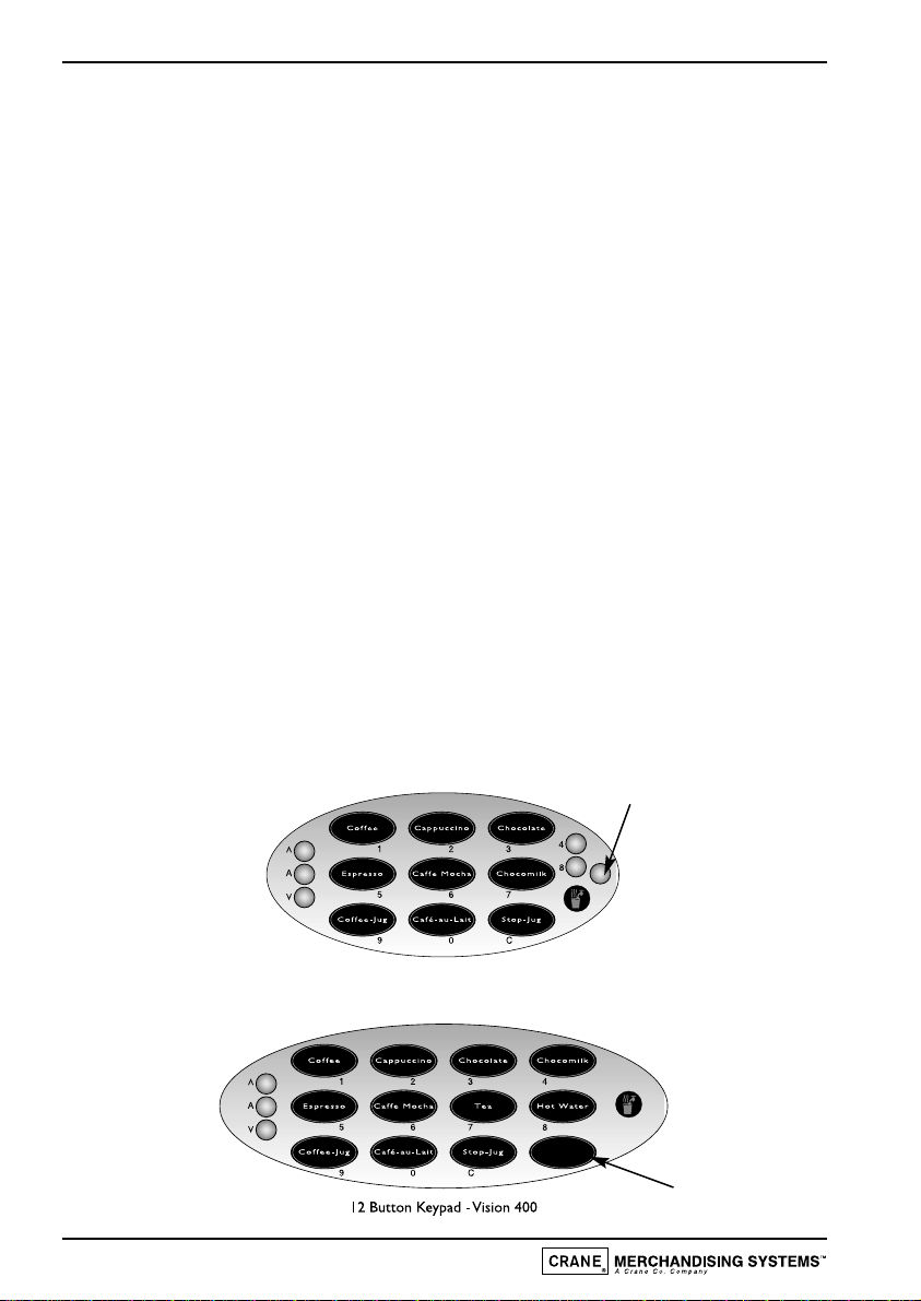
Programming mode utilises the front panel keys,as defined in Figure 1,in order to enter
values and commands.
Figure 1
14
Operator’s Manual
9 Button Keypad -Vision 300
Blank
Blank
During programming the keys are used as follows:
Buttons 0-9 Used for entering data
‘C’Used for correcting data
‘Blank’For moving to a higher programme level
▲For indexing up in a programme, or incrementing data
▼For indexing down in a programme, or entering data
‘A’For entering data in a programme, or moving to a lower
programme
Accessing the Programming Mode
1. Press the blank key twice followed by the Operator’s Access Code - selection
button 1 followed by 7. Code entry errors may be erased using the cancel (C) key.
2. With the correct code entered the title of the first sub-program will be displayed.
The LCD will display the message:
3. To step through the sub programs, press either the up (▲) or down (▼) keys.
4. To access a displayed sub program, press the access (A) key.
5. If any numerical data parameter is entered, it may be changed in one of two ways
dependant upon machine type:
(a) Pressing the up (▲) or down (▼) keys increases or decreases the number on
each key press.
(b) Keying in the actual digits of the number required. Using this method, the new
number will be displayed in place of the current parameter.
6. Once the correct number has been entered,press the access (A) key to overwrite
the old parameter with the new number.To retain the old parameter press either
the ‘blank’or cancel (C) key.
Note: It is not possible to vend a drink in Programming mode.
15
Operator’s Manual
OPERATIONS
SUB PROGRAM
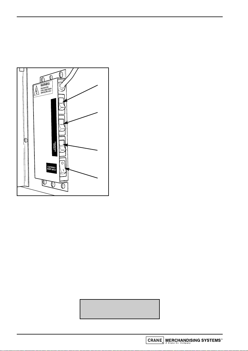
Function Switches
Vision Xtra machines are fitted with 4 switches, mounted in a panel located to the
right of the ingredient canisters (figure 2).
Figure 2
1. Flush Switch
2. Counters Switch
3. Reset Counters Switch
4. Electronics On/Off Switch
These switches are used for the following functions:
Electronics On/Off Switch
When switched to off (0), the Electronics on/off switch (4) completely disables the
machine’s electrical functions, allowing the operator to safely carry out machine
cleaning and filling etc.
Flush Switch
1. The Flush sequence operates automatically and flushes the complete water
system. Before the sequence begins, the system waits until the water is at the
correct temperature determined by the thermostat. During the entire sequence,
the LCD displays the message:
16
Operator’s Manual
VIEW
COUNTERS
FLUSH
1
2
3
1
2
3
4
SORRY NOT IN USE
SELF CLEANING

2. In order to guarantee the highest standards of cleanliness, the boiler fill valve is
disabled,ensuring that the water used in the sequence is delivered at the optimum
temperature to kill any micro-organisms. Each hot water valve and the
corresponding whipper is switched on in sequence for a pre-set flush time.
3. Once the flush cycle is complete, the boiler refills and when the water is at the
correct temperature, the machine returns to standby mode, ready to vend.
4. To flush the machine:
Caution: Ensure that the waste tray is empty (and in place) and keep hands away
from the dispensing area whilst the flushing cycle is in operation.
a. Open the front door of the machine.
b. Press and release the Flush switch (1).
c. Empty the waste tray when complete.
Counters Switch
1. Internal counters monitor the numbers of vends of each drink type, the number
of jug vends, free vends and the weights of each of the ingredients used.
2. To view the counters:
a. Open the front door of the machine.
b. Press and release the Counters switch (2).
c. Step through the list using the ▲and ▼keys on the front panel.
d. When complete, press the ’Blank’or cancel (C) key to return to standby
mode.
Reset Counters Switch
1. Once you have taken note of the values of the internal counters, you can reset
all counters to zero.
2. To reset the counters:
a. Enter Programming mode (as described previously).
b. Open the machine door and press the ‘Reset Counters’switch (3).
3. All counters are cleared at this point and the machine gives an intermittent beep
and flashes the message (shown below) to warn the operator:
17
Operator’s Manual
COUNTERS RESET

4. To clear the warning and return to standby mode, press cancel (C) key.
Sub Programs
The sub programs within the Operator’s Program are as shown in the following diagram
- figure 3.
Figure 3
To access a sub program within the Operator’s Program, enter the programming mode
as described previously.To step through the sub programs, press either the up (▲) or
down (▼) keys.To access a displayed sub program, press the access (A) key.
Note: The Drink Price, Alternative Tariff 1, Alternative Tariff 2 and Alternative Price
period sub programs are only applicable to Vision Xtra machines fitted with a coin
pod and a coin/card system.
1. Operations Sub-Program
This sub-program allows the operator access to the following functions:
(a) Service: When accessed,this function allows the operator to test vend each
drink selection, for example after carrying out the cleaning procedure.
(b) Self Clean: This function allows the operator to flush the entire mixing
system.
(c) Counter Reset:This function enables the operator to reset all vend/weight
counters to zero.
18
Operator’s Manual
Non Re-settableVend Counters
This manual suits for next models
2
Table of contents
Other Stentorfield Coffee Maker manuals


Popular Coffee Maker manuals by other brands


Gaggia
Gaggia GRAN GAGGIA operating instructions

Orbegozo
Orbegozo EX 6000 instruction manual

EspressoWorks
EspressoWorks 30 PC All-In-One BARISTA PRO Series quick start guide

Gaggia Milano
Gaggia Milano NEW CLASSIC RI9480 operating instructions

Waring
Waring WC1000 Instruction book

Bunn
Bunn AXIOM 35-3 Installation & operating guide