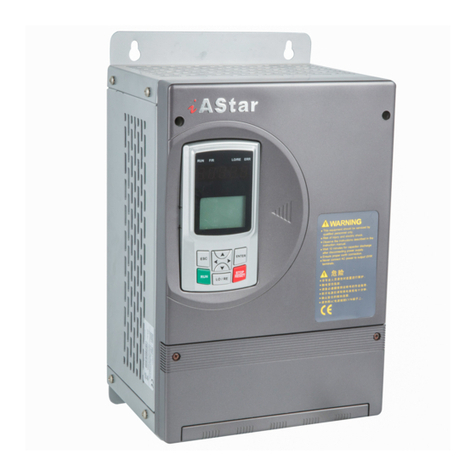
Step Electric AS500 Series Manual

I
Using Instructions for Series AS500 Inverter for Water Pump
AS500 Universal Vector Inverter with high performance
Product Instruction
Publication state: standard
Product version: V1.00
All Copyright reserved by Shanghai Sigriner STEP
Electric Co.,Ltd.
The information in this document is subject to change
without prior notice. No part of this document may in
any form or by any means (electronic, mechanical,
micro-coping, photocopying, recording or otherwise) be
reproduced, stored in a retrial system or transmitted
without prior written permission from Shanghai Sigriner
STEP Electric Co., Ltd.

Shanghai Sigriner STEP Electric Co., Ltd.
Content
Chapter 1 Safety instructions............................................................................................................1
1.1 SAFETY INFORMATION .....................................................................................................................1
1.2 SAFETY PRECAUTIONS ....................................................................................................................2
1.2.1 Application................................................................................................................................2
1.2.2 Examination for arrival of goods...............................................................................................2
1.2.3 Transport and storage ..............................................................................................................3
1.2.4 Installation ................................................................................................................................3
1.2.5 Wiring .......................................................................................................................................4
1.2.6 Test run ....................................................................................................................................4
1.2.7 Maintenance and inspection.....................................................................................................6
1.2.8 Discarding disposal ..................................................................................................................6
1.2.9 Others ......................................................................................................................................7
1.3 PRECAUTIONS ................................................................................................................................7
1.3.1 Motor insulation inspection.......................................................................................................7
1.3.2 Thermal protection of motor .....................................................................................................7
1.3.3 Motor heat and noise................................................................................................................7
1.3.4 Caution to input and output ......................................................................................................8
1.3.5 Usage out of the Range of Rated Voltage ................................................................................9
1.3.6 Lightning Strike Protection........................................................................................................9
1.3.7 Leakage protection...................................................................................................................9
1.3.8 Derating....................................................................................................................................9
1.3.9 About applicable motor...........................................................................................................10
Chapter 2 Product overview ..............................................................................................................1
2.1 NAMEPLATE INFORMATION ...............................................................................................................1
2.1.1 Inverter Nameplate Information................................................................................................1
2.1.2 Product (order number) information .........................................................................................2
2.1.3 Product specifications ..............................................................................................................3
2.2 INVERTER TECHNICAL INDEX AND SPECIFICATION...............................................................................5
2.3 INSTALLATION DIMENSION OF INVERTER ............................................................................................8

III
Using Instructions for Series AS500 Inverter for Water Pump
2.3.1 Appearance and components of inverter..................................................................................8
2.3.2 External dimensions and installation dimensions of inverter ....................................................9
2.3.3 Dimensions of inverter operator ............................................................................................. 11
2.4 OPTIONS OF BRAKING UNIT AND BRAKING RESISTOR ....................................................................... 11
Chapter 3 Inverter installation ...........................................................................................................1
3.1 INSTALLATION STEPS .......................................................................................................................1
3.2 MECHANICAL INSTALLATION .............................................................................................................1
3.2.1 Installation environment ...........................................................................................................1
3.2.2 Installation orientation and space requirement .........................................................................3
3.2.3 Installation procedure of inverter ..............................................................................................5
3.3 REMOVAL AND INSTALLATION OF THE OPERATION PANEL AND COVERS .................................................5
3.3.1 Removal and installation of the operator ..................................................................................5
3.3.2 Opening and Closing of the Terminal Cover.............................................................................6
3.3.3 Removal and installation of the front panel ..............................................................................7
Chapter 4 Inverter wiring ...................................................................................................................1
4.1 CONNECTIONS TO PERIPHERAL DEVICES...........................................................................................2
4.1.1 Connection diagram to peripheral devices ...............................................................................2
4.1.2 Wiring with peripheral devices in main circuit...........................................................................3
4.2 INVERTER TERMINAL WIRING ..........................................................................................................13
4.2.1 Wiring diagram for inverter terminals......................................................................................14
4.2.2 Wiring precautions .................................................................................................................17
4.3 WIRING MAIN CIRCUIT TERMINALS ..................................................................................................18
4.3.1 Alignment of main circuit terminals.........................................................................................18
4.3.2 Symbols and Functions of Main Circuit Terminals..................................................................18
4.3.3 Wire sizes of main circuit........................................................................................................19
4.3.4 Illustration of main circuit wiring .............................................................................................21
4.4 COUNTERMEASURES AGAINST NOISE..............................................................................................26
4.4.1 Install a specialized noise filter on the output side .................................................................26
4.4.2 Connection of surge suppressor on the output side ...............................................................26
4.4.3 Main circuit wiring...................................................................................................................27

Shanghai Sigriner STEP Electric Co., Ltd.
4.4.4 Better countermeasures against noise...................................................................................27
4.4.5 Relationship between cable length and carrier frequency ......................................................28
4.5 WIRING THE CONTROL CIRCUIT TERMINALS .....................................................................................28
4.5.1 Control circuit terminals..........................................................................................................28
4.5.2 TERMINAL SYMBOLS OF CONTROL CIRCUIT .................................................................................29
4.5.3 Control circuit terminal functions ............................................................................................29
4.5.4 Cable specifications of control circuit wiring ...........................................................................31
4.5.5 Control circuit terminal wiring .................................................................................................32
4.5.6 Other precautions for wiring ...................................................................................................36
4.6 WIRING PG CARDS.......................................................................................................................36
4.6.1 ABZ Increment PG Card ........................................................................................................37
4.6.2 SIN/COS PG card ..................................................................................................................39
4.6.3 PG card terminal wiring precaution ........................................................................................41
Chapter 5 Debugging and test run....................................................................................................1
5.1 RUN COMMAND SETTING .................................................................................................................2
5.1.1 Inverter run command channel.................................................................................................2
5.1.2 Inverter frequency setting channel ...........................................................................................2
5.1.3 Working state of inverter ..........................................................................................................2
5.1.4 Run modes of inverter ..............................................................................................................3
5.2 OPERATION GUIDE ..........................................................................................................................3
5.2.1 Function of digital operator components ..................................................................................4
5.2.2 LED indicator............................................................................................................................4
5.2.3 LED digital tube........................................................................................................................5
5.2.4 LCD display..............................................................................................................................5
5.2.5 Keyboard..................................................................................................................................5
5.3 OPERATION OF LCD OPERATOR.......................................................................................................6
5.3.1 Power on and initialization........................................................................................................6
5.3.2 Display after Power on .............................................................................................................6
5.3.3 【Monitoring State】................................................................................................................6
5.3.4 【Panel Control】....................................................................................................................7
5.3.5 Operation mode .......................................................................................................................8

V
Using Instructions for Series AS500 Inverter for Water Pump
5.4 INTEGRATED DISPLAY OPERATOR.................................................................................................... 11
5.4.1 Function of each display terminal...........................................................................................12
5.4.2 Key functions..........................................................................................................................12
5.4.3 Description of indicators .........................................................................................................13
5.4.4 LED display ............................................................................................................................13
5.5 OPERATION OF INTEGRATED DISPLAY TERMINAL ..............................................................................13
5.5.1 Initial power-on.......................................................................................................................13
5.5.2 Guide to quick debugging.......................................................................................................14
5.6 EXAMPLE FOR OPERATION .............................................................................................................19
5.7 FAULT INDICATION .........................................................................................................................19
Chapter 6 Chapter Six Function Parameter Tables .........................................................................1
6.1 6.1FUNCTION CODE PARAMETER TABLE EXPLANATION .......................................................................1
6.2 FUNCTION CODE PARAMETER SHORT LIST.........................................................................................1
6.2.1 P0X Group user parameters..................................................................................................1
6.2.2 P1X Group Control parameters ...........................................................................................2
6.2.3 P2X Group motor parameters................................................................................................8
6.2.4 P3X Group digital parameters .............................................................................................13
6.2.5 P4X Group speed control parameters .................................................................................17
6.2.6 P5X group process control parameters ...............................................................................19
6.2.7 P6X group Vector control parameters ....................................................................................25
6.2.8 P7X group incremental control parameters ............................................................................ 28
6.2.9 P8X group communication parameters..............................................................................32
6.2.10 P9X Group fault and display parameters..............................................................................35
6.3 PARAMETER RECORD SHEET OF USERS ..........................................................................................38
Chapter 7 Parameter description ......................................................................................................1
7.1 ABOUT THE MAIN MENU ...................................................................................................................1
7.1.1 Parameter setting.....................................................................................................................1
7.1.2 Motor learning ..........................................................................................................................1
7.1.3 Fault check...............................................................................................................................3
7.1.4 Parameter processing ..............................................................................................................3

Shanghai Sigriner STEP Electric Co., Ltd.
7.2 PARAMETER GROUP CLASSIFICATION AND FORMAT ............................................................................4
7.2.1 Parameter group format ...........................................................................................................4
7.2.2 Parameter group area division .................................................................................................4
7.3 GROUP P0X: USER PARAMETER GROUP ...........................................................................................5
7.3.1 Group P00: basic function parameter.......................................................................................5
7.3.2 Group P01~09: User function parameter (abbreviated): .........................................................6
7.4 GROUP P1X: CONTROL PARAMETER GROUP .....................................................................................6
7.4.1 Group P10 Basic control parameter .........................................................................................6
7.4.2 Group P11: start control parameter ........................................................................................11
7.4.3 Group P12: stop control parameter ........................................................................................15
7.4.4 Group P13 Braking function V/F control parameter .............................................................17
7.4.5 Group P14 V/F control parameter ..........................................................................................18
7.5 GROUP P2X: MOTOR PARAMETER GROUP.......................................................................................19
7.5.1 Group P20: basic motor parameter ........................................................................................19
7.5.2 Group P21: advanced motor parameter .................................................................................21
7.5.3 Group P22: motor auxiliary parameter ...................................................................................23
7.5.4 Group P23: motor protection parameter:................................................................................24
7.6 GROUP P3X: TERMINAL PARAMETER GROUP...................................................................................26
7.6.1 Group P30: digital quantity input parameter ...........................................................................26
Chapter 8 Fault inspection ................................................................................................................1
8.1 PROTECTION AND INSPECTION.........................................................................................................1
8.2 WORKFLOW OF FAULT DIAGNOSIS ....................................................................................................7
Chapter 9 Servicing and maintenance..............................................................................................1
9.1 GUARANTEE PERIOD .......................................................................................................................1
9.2 PRODUCT INQUIRY ..........................................................................................................................2
9.3 DAILY INSPECTION ..........................................................................................................................2
9.4 PERIODIC INSPECTION.....................................................................................................................2
Appendix A Electromagnetic compatibility ................................................................................................1
A.1 Noise restraint....................................................................................................................................1

VII
Using Instructions for Series AS500 Inverter for Water Pump
A.1.1 Noise type .......................................................................................................................................1
A.1.2 Noise transmission..........................................................................................................................1
A.1.3 Basic Countermeasures for Noise Restraint ...................................................................................2
A.2 Wiring Requirements..........................................................................................................................3
A.2.1 Cable laying ....................................................................................................................................3
A.2.2 Cable cross-section area ................................................................................................................4
A.2.3 Shielded cable ................................................................................................................................4
A.2.4 Installation of shielded cable ...........................................................................................................4
A.3 Grounding ........................................................................................................................................4
A.3.1 Grounding method ..........................................................................................................................4
A.3.2 Grounding precautions....................................................................................................................5
A.4 Surge absorber installation ................................................................................................................6
A.5 Leakage current and countermeasures..............................................................................................6
A.5.1 Leakage current to earth .................................................................................................................7
A.5.2 Leakage current between lines .......................................................................................................7
A.6 Restraint of radiation from inverter.....................................................................................................8
A.7 Application of filter for power lines .....................................................................................................9
A.7.1 Functions ........................................................................................................................................9
A.7.2 Installation of filter for power lines...................................................................................................9
A.8 EMC installation areas .....................................................................................................................10
A.9 Precautions for inverter electric installation......................................................................................12
A.10 EMC Standards for AS500 Inverter................................................................................................13
Appendix B Inverter accordance standards............................................................................................15
Appendix C Letter of Complaint..............................................................................................................16
Appendix D Warranty card .....................................................................................................................17
Appendix E To the Customer....................................................................................................................1


1-1
Cha
p
ter 1
Using Instructions for Series AS500 Inverter for Water Pump
Safet
y
instructions
Chapter 1 Safety instructions
This chapter describes the safety instructions and precautions required for the
application of AS500 inverters, including the general information, safety information,
application, confirmation for arrival of goods, transport and storage, installation,
safety instruction for wiring, debugging/operation, troubleshooting, discarding
disposal, etc. To ensure personal safety and extend the service life of equipments
and their connecting devices, be sure to read the following safety regulations and
warnings, and all warning signs attached to equipments prior to installing and
debugging the inverter. Please read this information carefully.
1.1 Safety information
The following symbols with texts are used in this manual for safety-related contents.
Please comply with these regulations as they are very important.
DANGER
Indicate precautions that, if not heeded, could possibly result
in fire, serious personal injury or even death.
CAUTION
Indicate precautions that, if not heeded, could possibly result
in relatively serious or minor injury, damage to the product, or
faulty operation.
IMPORTANT Indicate important information that should be memorized.
In addition, even for CAUTION matters, a major accident may be caused
sometimes according to specific circumstances.

1-2
Shanghai Sigriner STEP Electric Co., Ltd.
Cha
p
ter 1Safet
y
instructions
1.2 Safety precautions
1.2.1 Application
DANGER
This series of inverter is used to control the variable speed operation of three phase
motor, but not used for single phase motor or other applications; or else, inverter fault or
fire may be caused.
This series of inverter can not be simply used in the applications directly related to the
human safety, such as the medical equipment.
This series of inverter is produced under strict quality management system. If the
inverter failure may cause severe accident or loss, safety measures, such as
redundancy or bypass, shall be taken.
1.2.2 Examination for arrival of goods
CAUTION
The delivered goods must not be damaged and shall be in conformity with information
on the purchase order. If the goods are found to be damaged or do not conform to the
purchase order, please contact your local dealer or agent.
If the inverter is found to be damaged or lack of parts, the inverter cannot be installed or
put into operation. Otherwise, accident may be caused.

1-3
Cha
p
ter 1
Using Instructions for Series AS500 Inverter for Water Pump
Safet
y
instructions
1.2.3 Transport and storage
CAUTION
During transport, avoid acute vibration and strike.
If the inverter is found to be damaged, inform the transportation company immediately.
The transport and storage of inverter must comply with the specific environmental
conditions.
If the inverter has been stored for more than 1 year, it is necessary to recharge the
capacitor.
1.2.4 Installation
DANGER
Be care to fire or electric shock!
Do no install the inverter in the areas where inflammable, explosive, or corrosive
substances or water exist.
CAUTION
When handling and installing the product, please hold the product bottom. Do not hold
the enclosure only. Otherwise, your feet may be injured and the inverter may be
damaged because of dropping.
Do not install the inverter in the areas where are easy to suffer continuous vibration,
impact or electromagnetic interference.
The inverter shall be mounted on the fire retardant surface, such as metal, and kept far
away from heat source.
Take caution to fire! Keep sundries away from the inside of the inverter and its radiator
(e.g., chips, iron filings, dust, scrip, etc.).
A certain gap shall be reserved among the inverters, or between the inverter and
another equipment / inner wall of cabinet (Specific requirements for gap refer to
“Installation orientation and space”).
Do not install the inverter horizontally.

1-4
Shanghai Sigriner STEP Electric Co., Ltd.
Cha
p
ter 1Safet
y
instructions
1.2.5 Wiring
DANGER
The wiring must be conducted by qualified electricians. Otherwise, there will be risk of
electric shock or inverter damage.
Before wiring, confirm that the power supply is disconnected. Otherwise, there will be
risk of electric shock or fire.
The grounding terminal PE must be reliably grounded, otherwise, the inverter enclosure
may become live.
Please do not touch the main circuit terminal. The wires of the inverter main circuit
terminals must not contact the enclosure. Otherwise, there will be risk of electric shock.
If the power supply is switched on while the running signal is energized, the motor will
start running automatically. So to make sure the running mode is OFF before
connecting the power supply, otherwise, there will be risk of personal injury.
If the 3-wire sequential control is set, begin the wiring of control loop after setting the
parameters of multifunctional input terminals. Otherwise, there will be risk of personal
injury by motor rotation.
1.2.6 Test run
CAUTION
Never connect the power input cable to the motor terminals U/T1, V/T2, and W/T3, and
do not connect the motor cable to the power input terminals R/L1, S/L2, and T/L3.
The power line and signal line must be laid in the different grooves, apart 10 cm at
least. The connected cables may not contact with the rotating mechanical parts.
It is forbidden to connect the output terminal of the inverter to the capacitor or LC/RC
noise filter with phase lead, otherwise, the internal components of the inverter may be
damaged.
The wires of the main circuit terminals shall adopt lugs with insulating sleeves.
For input and output cable of the inverter, please select the cable with proper section
according to the power of the inverter.

1-5
Cha
p
ter 1
Using Instructions for Series AS500 Inverter for Water Pump
Safet
y
instructions
When the length of the cable between the inverter and the motor is more than 30m or
several motors work simultaneously, it is suggested to use output reactor to avoid the
inverter failure caused by the over current of the distribution capacitor.
Please do not use other loads except for three phase AC motor.
At the time of self-tuning learning, please confirm the load removal. Before end of self
learning, repeat start and stop of motor, so please do not touch the motor. Otherwise,
personal injury may be caused.
DANGER
Power supply can only be connected after the front cover is installed. It is forbidden to
remove the cover in power-on condition; otherwise, there will be risk of electric shock.
Provide emergency stop switch additionally (stop buttons only with function settings are
valid).
The alarm signal can only be reset after the running signal has been cut off. Otherwise,
personal injury may be caused.
CAUTION
Debug the no-load motor firstly, then the load motor.
While the equipment is running or after the power is turned off within a certain period,
do not touch the inverter radiator, motor or other high temperature components, or you
will be burnt.
Do not switch off and on the inverter time after time, or else the equipment / system
may be damaged.
Before operation, please confirm if the motor or machinery is in the allowable use
range, otherwise, the equipment may be damaged.
When it is used on lifting equipment, a mechanical brake shall also be equipped.
Please do not change the inverter parameter randomly. Most of the factory set
parameters of the inverter can meet the operating requirement, and the user only
needs to set some necessary parameters. Any random change of the parameter may
cause the damage of the mechanical equipment.

1-6
Shanghai Sigriner STEP Electric Co., Ltd.
Cha
p
ter 1Safet
y
instructions
1.2.7 Maintenance and inspection
DANGER
Terminals of the inverter are under high voltage; they are very dangerous. Therefore,
please do not touch them, or there will be risk of electric shock.
Under power-on circumstance, take care to mount the protecting cover. In addition,
when dismounting the cover, be sure to cut off the circuit breaker. Or else, there will be
risk of electric shock.
Wait for at least 10 minutes after power off of main circuit or confirm that the charging
indicator is off before maintenance and inspection to prevent the harm caused by the
residual voltage of the capacitor to persons.
With exception of the specified personnel, never others may repair, inspect or change
components. [Prior to working, please remove the metal accouterment (watch, ring,
etc.)]. During the operation, please use the insulated tools. Or otherwise, there will be
risk of electric shock.
CAUTION
The circuit boards have large scale CMOS IC. Please do not touch the board to avoid
the circuit board damage caused by electro static.
1.2.8 Discarding disposal
DANGER
Explosion may occur during burning of the electrolytic capacitor on the main circuit or
PCB. The burning of plastic parts on the inverter will generate poisonous gases.
Therefore, the discarding disposal of this equipment must be executed in accordance
with laws and regulations on treatment of industrial electronic waste enacted by related
environmental protection organizations.

1-7
Cha
p
ter 1
Using Instructions for Series AS500 Inverter for Water Pump
Safet
y
instructions
1.2.9 Others
CAUTION
During transport or under any specific condition, the inverter may not be placed in a
halogen (fluorine, chlorine, bromine, iodine) environment. Otherwise, the inverter may
be damaged or its components will be burned out.
1.3 Precautions
1.3.1 Motor insulation inspection
When the motor is used for the first time, or reused after storing for a long time, or
in a regular inspection, the user must inspect the insulation of the motor to prevent
the poor insulation of the windings of motor from damaging the inverter. The motor
connection must be divided from the inverter during the insulation inspection. It is
recommended to use a 500 V Mega-Ohm-Meter and the insulation resistance shall
not be less than 5 MΩ.
1.3.2 Thermal protection of motor
If the rated capacity of the motor selected is not matching that of the AS500 series
inverter, especially when the rated power of the inverter is greater than that of the
motor, make sure to adjust the parameters for motor protection inside the AS500
inverter or to install a thermal relay to the motor to guarantee the protection to the
motor.
1.3.3 Motor heat and noise
Since the output voltage of the inverter is PWM wave with some harmonic, the
temperature rise, noise and vibration may increase compared with the inverter
running at power frequency.
When a conventional motor driven by an inverter is in prolonged low speed
operation, the motor temperature will rise because the heat dissipation effect of the

1-8
Shanghai Sigriner STEP Electric Co., Ltd.
Cha
p
ter 1Safet
y
instructions
motor becomes poorer. If a prolonged constant-torque low-speed operation is
required, a variable frequency motor must be selected, or forced air cooling be
provided.
1.3.4 Caution to input and output
Because the AS500 inverter outputs PWM wave, the capacitor used for improving
power factor and piezoresistance used for lightening-proof should not be installed
at the output side of the inverter. Otherwise the inverter may have transient
over-current and may be damaged.
No permission for capacitor connection at the output side of the inverter refers to
Figure 1-1.
Figure 1-1 Schematic diagram for non-permission for capacitor connection at the output side of the
inverter
If a contactor is required to be installed between the inverter input terminal and the
power supply, it is prohibited to start or stop the inverter with the contactor.
If switches like contactors are connected between the output terminal and the motor,
make sure to start and stop the inverter when the inverter has no output, it is
prohibited to pick up the contactor when the inverter is outputting, otherwise the
modules in the inverter may be damaged.
Terminals are recommended for the startup / shutdown of the inverter. The user is
absolutely not permitted to directly shut down or start up the inverter via such
switches as contactor on the input terminal of the inverter; otherwise, damages to
equipment may be caused.

1-9
Cha
p
ter 1
Using Instructions for Series AS500 Inverter for Water Pump
Safet
y
instructions
1.3.5 Usage out of the Range of Rated Voltage
The AS500 series inverter shall not be used out of the specified range of operating
voltage. Otherwise, the internal components of the inverter may be damaged. If
needed, please use corresponding voltage regulation device to change the voltage.
1.3.6 Lightning Strike Protection
There are lightning over current protection devices inside the inverter, which has
certain self-protection capacity for sensing the lightning. The user should install
other lightning protection device at the front end of the inverter where lightning
strike occurs frequently.
1.3.7 Leakage protection
Quick startup or shutdown during inverter operation necessarily induces
high-frequency leakage currents, which may sometimes cause misoperation of the
leakage protection circuit. In the event of the aforesaid problems, reduce the carrier
frequency and the length of the lead-in wire appropriately; besides, the leakage
protector must be correctly installed.
Keep the following points in mind when installing a leakage protector:
It is more proper to install the protector at the input terminal of the inverter and
behind the air circuit breaker (not a fuse circuit breaker).
The selected leakage protector must be insensitive to higher harmonics
(sensitivity: Above 30 mA) or specially suited for inverter applications. If a common
leakage protector is selected, it must have the sensitivity above 200 mA and the
action time above 0.1 s.
1.3.8 Derating
When the ambient temperature exceeds 40 , the inverter must be derated by 1%℃
for every increment of one degree Celsius. Also, forced external heat dissipation
must be provided.
At 1,000 m above sea level, the thinner air will deteriorate the heat dissipation effect

1-10
Shanghai Sigriner STEP Electric Co., Ltd.
Cha
p
ter 1Safet
y
instructions
of the inverter. Therefore, the inverter must be derated by 1% for every increment of
100 m.
When the set carrier frequency exceeds the factory settings, the inverter must be
derated by 10% for every increment of 1 kHz.
For derating, please contact our company for detailed technical support.
1.3.9 About applicable motor
The inverter is applicable to asynchronous squirrel-cage motor and permanent
magnet synchronous motor. Please be sure to select the applicable inverter
according to the Nameplate of the motor.
The inverter has already been configured with default parameters which are
applicable to asynchronous squirrel-cage motor. To perform the motor parameter
identification according to the actual conditions will promote the operation effect.
The short circuit of cable or motor interior may cause the inverter alarm or to be
damaged. Therefore, perform insulation short test for the initially installed motor
and cables, and also make such test during the routine maintenance. Please make
sure that the inverter be cut from the testing parts when the test is undergoing.

2-1
Cha
p
ter 2
Using Instructions for Series AS500 Inverter for Water Pump
Product overview
Chapter 2 Product overview
AS500 series consist of class 400 V (380 V to 460 V) and class 200 V (220 V to 240
V) universal inverters for current vector control, which apply to three phase AC
asynchronous squirrel-cage motor and permanent magnet synchronous motor with
1.1 to 75 kW capacity. AS500 series inverters with default settings provide an ideal
solution for most simple motor control application. Moreover, by setting related
parameters, AS500 may be applied to advanced operation by motor control.
2.1 Nameplate information
The nameplate is attached to the side of the inverter. The nameplate includes
information such as model, specifications, lot number, serial number, and so on.
Figure 2-1 Inverter nameplate (example)
2.1.1 Inverter Nameplate Information
The Inverter nameplate is shown in Figure 2-2.
The nameplate includes information such as model, specifications, lot number and
Nameplate

2-2
Cha
p
ter 2 Product overview
Shanghai Sigriner STEP Electric Co., Ltd.
so on.
Model →MODEL: AS500 4T 0022
Applicable motor power →POWER: 22kW
Input specifications →INPUT: 3PH AC 380 – 460 V 50/60 Hz 52 A
Output specifications →OUTPUT: 34 kVA 0 – 460 V 0-120 Hz 48 A
Number →No.:
Serial number →SER. No.:
Shanghai Sigriner STEP Electric Co., Ltd
Figure 2-2 Nameplate information
2.1.2 Product (order number) information
In “Inverter model” on the nameplate, inverter specification, voltage class, type and
maximum capacity of applicable motor are indicated with figures and letters.
This manual suits for next models
25
Table of contents
Other Step Electric Inverter manuals
