Sollatek PowerBack PB3000S User manual

The Sollatek
PowerBack PB3000S / PB5000S
Inverter With Solar Charger Controller
User Instructions
www.sollatek.com
the power to protect
the power to protect
Important: This manual contains important safety instructions.
Keep this manual handy for reference.
• Before using this product please read all instructions carefully.
• Keep these instructions for future reference.
• All specifications are subject to change without prior notice.

Important Safety Warning
WARNING: This chapter contains important safety and operating
instructions. Read and keep this User Guide for future reference.
General Precautions
1. Before using the unit, read all instructions and cautionary markings on:
(1) The unit (2) the batteries (3) all appropriate sections of this manual.
2. CAUTION --To reduce risk of injury, charge only deep-cycle lead acid type
rechargeable batteries. Other types of batteries may burst, causing personal
injury and damage.
3. Do not expose the unit to rain, snow or liquids of any type. The unit is
designed for indoor use only. Protect the unit from splashing if used in vehicle
applications.
4. Do not disassemble the unit. The maintenance information is only for
service technicians. When service or repair is required, contact your
supplier for further arrangements. Incorrect re-assembly may result in a
risk of electric shock or fire.
5. To reduce risk of electric shock, disconnect all wirings (AC mains, batteries,
solar panel) before attempting any maintenance or cleaning. Turning off the
unit might not eliminate the risk.
6. No terminals or lugs are required for hook-up of the AC wiring. AC wiring
must be no less than 10 AWG gauge copper wire and rated for 75oC or
higher.(Refer to equivalence table on page 10). Battery cables must be rated
for 75oC or higher and should follow the recommendation in the manual.
Crimped and sealed copper ring terminal lugs (refer to INSTALLATION
section) should be used to connect the battery cables to the DC terminals of
the unit. Soldered cable lugs are also acceptable.
7. Be cautious when working with metal tools on, or around batteries. Dropping
a tool and short-circuit the batteries or other electrical parts may result in
sparks and explosion.
8. No AC or DC disconnects are provided as an integral part of this unit.
Both AC and DC disconnects must be provided as part of the system
installation. See INSTALLATION section of this manual.

9. No over current protection for the battery supply is provided as an integral part
of this unit. Over current protection of the battery cables must be provided as
part of the system installation. See INSTALLATION section of this manual.
10. GROUNDING INSTRUCTIONS -This battery charger should be connected to
a grounded permanent wiring system. For most installations, the Ground Lug
should be bonded to the grounding system at one (and only one point) in the
system. All installations should comply with all national and local codes and
ordinances.
11. The unit must be installed and maintained by qualified staff. Please read the
manual carefully before installations & operations.
12. The unit contains energy source: the batteries and solar. All terminals and
sockets may be powered even when the unit is not connected to the mains.

Table of Content
1.#Overview#.......................................................................................................#1#
1.1#Key#Feature#..................................................................................................#1#
1.2#Product#Outlook#..........................................................................................#2#
1.3#Basic#System#Architecture#...........................................................................#3#
2.#INSTALLATION#...............................................................................................#4#
2.1#Unpacking#and#Inspection#...........................................................................#4#
2.2#Remove#bottom#cover#................................................................................#4#
2.3#Placement#...................................................................................................#4#
2.4#Battery#Connection#.....................................................................................#5#
2.5#AC#Connection#............................................................................................#7#
2.6#PV#connection#.............................................................................................#9#
3.#OPERATION#.................................................................................................#11#
3.1#LCD#display#introduction#..........................................................................#11#
3.2#LCD#display#setting:#..................................................................................#15#
3.3#Standby#Charging#Mode#...........................................................................#15#
3.4#Operation#Modes#(after#powered#on)#.....................................................#16#
3.5#Fault#Mode#...............................................................................................#19#
4.#SPECIFICATION#............................................................................................#19#
APPENDIX#A#.....................................................................................................#25#
APPENDIX#B#.....................................................................................................#28#

1. Overview
This is a pure sine wave stand-alone inverter/charger system combining the
function of inverter, solar charger and AC charger, and provides a long
run-time uninterruptible power supply. Its comprehensive LCD display
provides system status, and allows users to set output source priority, charger
source priority, charger current and so on.
1.1 Key Feature
•High-frequency switching technology for compact size and light weight
•Pure sine wave output for wide range of applications and harsh
environment
•Build-in solar charger controller with MPPT technology to optimize the
power utilization
•High efficient DC-to-AC conversion minimizing energy loss
•Standby Charging Mode enables battery charging even when the unit is
switched off
•Intelligent cooling fan control
•Input/output isolated design for the maximum operation safety
•LCD displays comprehensive operation status
•Configurable output source priority, charger source priority, charger
current and so on.
•Supports Home Appliances / Office Equipment/ Lighting Equipment/
Motor-based Equipment (such as Fan, Air-Conditioner, Washing
Machines)
•Thorough protections: Input low voltage / Overload / Short circuit / Low
battery alarm / Input over voltage / Over temperature/SCC over current
protection
•Rack design & wall-mounted design for flexible installation

1.2 Product Outlook
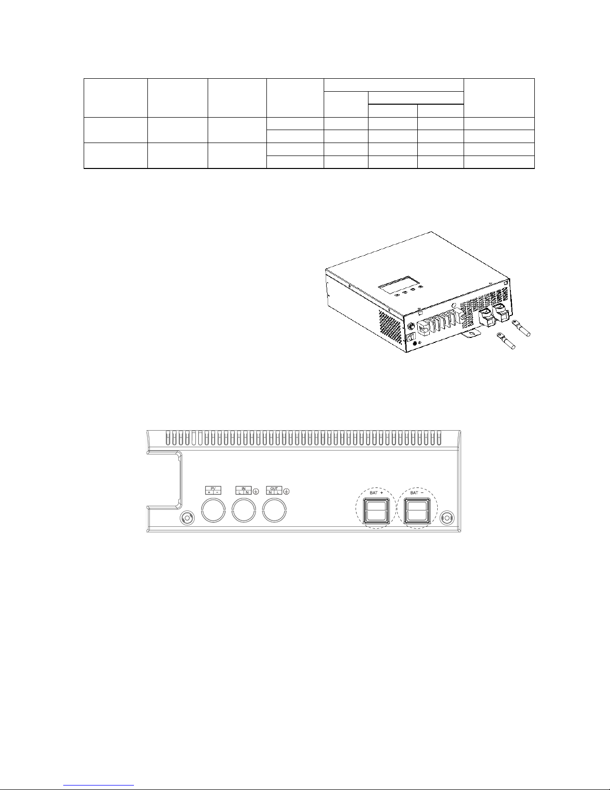
3K rear panel
5K rear panel
1. LCD display
2. LCD Configuration button: Enter configuration mode, and switch between
setting menus
3. LCD up/down button: Move to previous/next setting option
4. LCD ESC button: Return to main menu

5. LCD Enter button: Confirm setting
6. AC input circuit breaker
7. Power ON/OFF switch
8. PV input
9. AC input
10.AC output
11.AC Input & output GND
12.Battery input
1.3 Basic System Architecture
A typical application diagram for home and office applications is as shown below.
The inverter supports the following power sources as input:
•Generator or AC utility
•PV modules(optional)
•Batteries
And the inverter is capable of supplying various loads such as fluorescent lamp,
fan, TV, refrigerator, air conditioner and so on.

2. INSTALLATION
2.1 Unpacking and Inspection
The product package is shipped with the following items. Please call your
supplier or dealer if any items are missing.
!1 X Inverter
!1 X DC red cable
!1 X DC black cable
!1 X User’s manual
2.2 Remove bottom cover
Please take off bottom cover by removing
below 2 screws before connecting wires.
2.3 Placement
Choosing a location to install, the place should be a firm wall and a well-ventilated
room protected against rain, vapor, moisture and dust. The location should provide
adequate air flow around the Inverter with 30cm minimum clearance on all sides
for proper ventilation.
30cm
30cm
30cm
30cm

Use screws to mount the inverter to a solid surface. The recommended screw size
is M4*50~65mm.
##Screws locations of 3K model Screws locations of 5K model
2.4 Battery Connection
CAUTION: For safety operation and regulation compliance, it is requested to
install a separate DC over-current protector or disconnect device between battery
and inverter. Note that some installation requirements may not require a
disconnect device, however, an over-current protection installed is still required.
Please refer to typical amperage in below table as required fuse or breaker size.
WARNING! All wiring must be performed by a
qualified technician
WARNING! Check the polarity before connecting the battery
wires in order not to damage the inverter.
Recommended battery cable & cable terminal size:
Model
Number
Typical
Amperage
Battery
Capacity
Wire
Size
CABLE TERMINAL
Torque
value
Cable
mm2
Dimensions
D(mm)
L(mm)
PowerBack
PB3000S
110A
200AH
1*4AWG
22
6.4
35
5~ 8 Nm
2*6AWG
28
6.4
35
5~ 8 Nm
PowerBack
PB5000S
100A
200AH
1*4AWG
22
8.4
35
5~ 8 Nm
2*6AWG
28
8.4
35
5~ 8 Nm
Please follow below steps to connect the batteries:
Step 1 -Install a DC Circuit Breaker for positive (+) battery cable. The rating of the
DC Circuit Breaker must be at least
140Amp for POWERBACK PB3000S,
120Amp for POWERBACK PB5000S to
guarantee safe operation without
interruption. Keep the DC Circuit
Breaker off.
Step 2 - Connect a red cable to BAT+
terminal, and a black cable to BAT -
terminal of the inverter.
Knock off below “BAT+” and “BAT-” holes, cross red cable via “BAT+” hole and
cross black cable via “BAT-“ hole.
Step 3 - Connect the above mentioned red cable to the battery’s positive (+)
terminal and black cable to battery’s negative (-) terminal.
Step 4- After AC input and output wires are connected, switch on the DC Circuit
Breaker.
Note: Make sure the battery voltage meets the inverter’s specification:
POWERBACK PB3000S supports 24VDC battery system; POWERBACK
PB5000S supports 48VDC battery system. And use at least 200Ah capacity
battery for POWERBACK PB3000S & POWERBACK PB5000S.

2.5 AC Connection
CAUTION: Please install a separate AC breaker between inverter and AC input
power source. This will ensure the inverter can be securely disconnected during
maintenance and fully protected from over current of AC input. The recommended
spec of AC breaker 30A for POWERBACK PB3000S model, 40A for
POWERBACK PB5000S model. Be sure that AC source is switched off before
installing the circuit breaker.
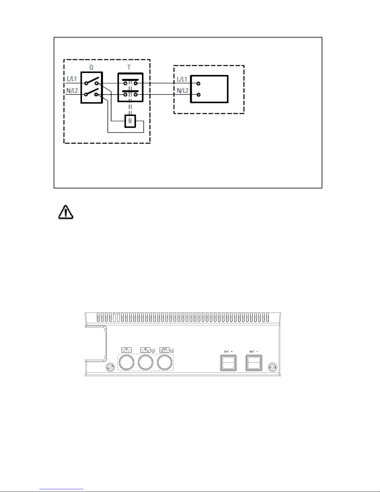
CAUTION: Since the inverter doesn’t have an automatic protection device against
back feed current. We recommends installing an external AC contactor (see the
diagram below). A warning label shall be attached on such AC contractor to
remind the user to disconnect the inverter before accessing the circuit.
The rated voltage and current of the AC contactor shall be no less than the
inverter’s rated voltage and current, and a minimum 1.6mm space clearance shall
be reserved.
A circuit breaker shall be installed between AC mains and the inverter in order to
disconnect the AC mains when needed. Surge protection is built in. For further
protection however, we recommend installing a Sollatek DSP and Sollatek AVS.
Contact us for further information.
Please follow the steps below to connect AC wires:
Step 1 - Disconnect the unit from the battery either by turning off the battery circuit
breaker or removing the battery cables from the battery. Note that
turning the unit off does not disconnect the batteries.
Step 2 - Remove bottom cover and knock off “PV”, “IN” & “OUT” holes.
Step 3 - Thread the AC input wires through “IN” hole of bottom cover and AC
output wires through “OUT” hole, then connect the AC input wires to input
terminal, AC output wires to output terminal & AC GND: GND
(green/yellow), Line (brown or black), and neutral (blue) wires.
Legend
B Coil Remote Switch
Q Magneto-Thermal Input Main Switch
T AC Contactor
N/L2 Neutral/L2
L/L1 L1 Line Input
External Distribution
Panel
POWERBACK PB3000S/
POWERBACK PB5000S#
WARNING! All wiring must be performed by a qualified technician.
WARNING! Operation without aproper grounding connection may
result in electrical shock.
Step 4 - Fix the bottom cover with two screws.
The recommended wire gauge and fixing torque are as below,
Model Number
AC Input
Wires Gauge
AC Output
Wires Gauge
AC GND
Wires Gauge
Torque
POWERBACK
PB3000S
12 AWG
12 AWG
12AWG
1.2~1.8 Nm
POWERBACK
PB5000S
10 AWG
10 AWG
10AWG
1.2~1.8 Nm
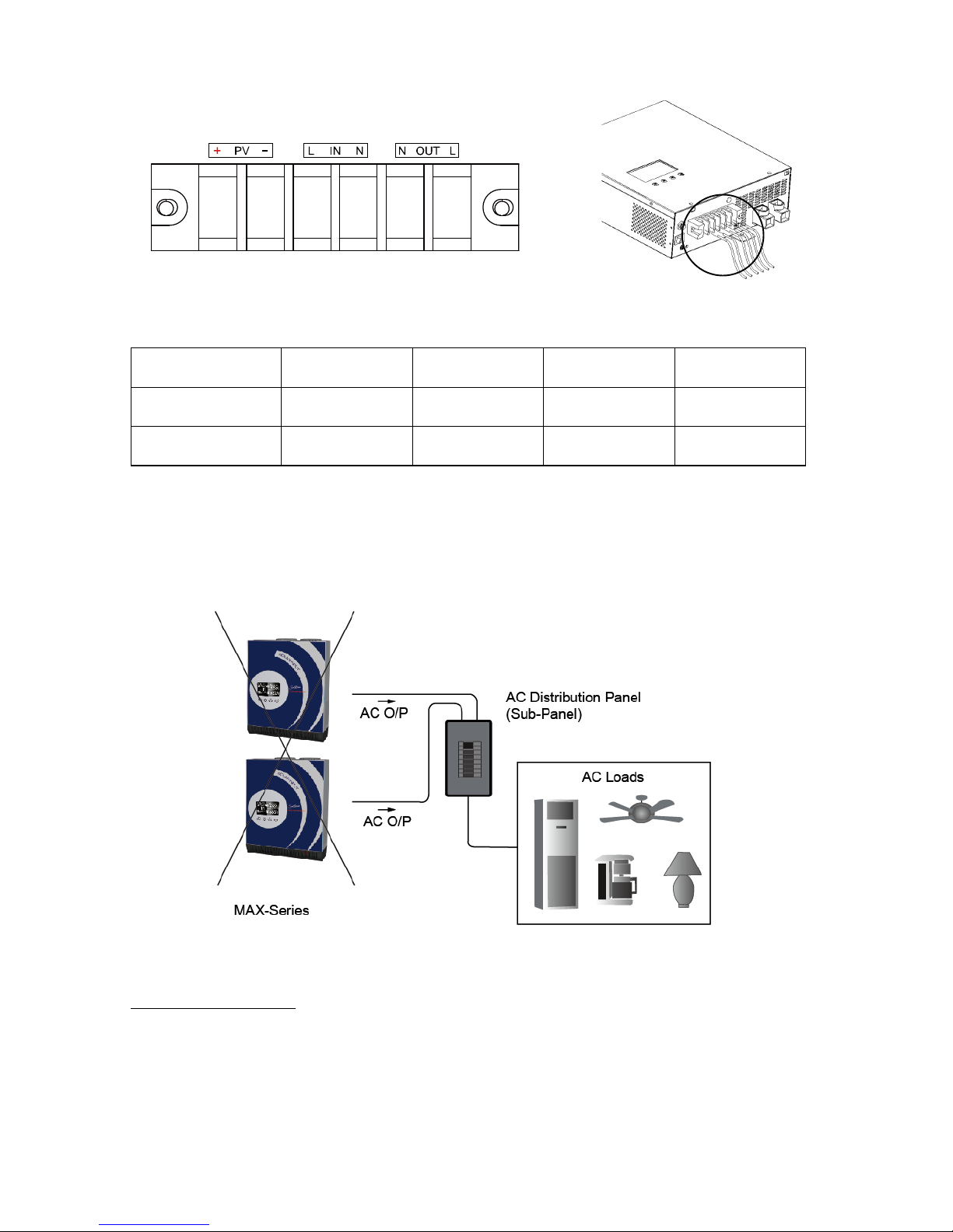
WARNING! The inverter is designed to be operated alone and is not designed for
parallel connection. Please DO NOT connect the inverter in parallel with any other
equipment.
2.6 PV connection
PV panel selection
PV string is a connection of PV panels whose output voltage and current vary
under different illumination. And just like battery, the PV panel can be connected in
either series or parallel as per needed. Please consult the supplier of PV panel so
that the operational voltage and current fall within the allowed range of the inverter
as set out in the specification.

Connect PV strings
CAUTION: As the PV string generates power as long as there is light, a circuit
breaker with 60A rating shall be installed as shown below, so that PV string can be
disconnected when needed (e.g. regular maintenance).
Please follow below step to implement PV module connection:
WARNING! All wiring shall be performed by a qualified technician.
WARNING! Please do not use PV panel which requires one
terminal connected to ground (e.g. thin-film panel).
Step 1 - Disconnect the unit from the battery either by turning off the battery
breaker or removing the battery cables from the battery. Note that turning
the unit off does not disconnect the batteries.
Step 2 - Remove bottom cover & knock off “PV” hole.
Step 3 - Thread the wires through “PV” hole on bottom cover, and then connect
the PV string wires to PV input terminals. Check the polarity of wires
before connecting to terminals.
Step 4 - Fix bottom cover with two screws.
Step 5 - Turn on battery breaker or connect battery cable.
The recommended wire gauge and fixing torque are as below,
Model Number
PV Input Wire Gauge
Torque
POWERBACK PB3000S
10 AWG
1.2~1.8 Nm
POWERBACK PB5000S
10 AWG
1.2~1.8 Nm
60Amps
3. OPERATION
After connecting batteries, AC input cables, and loads, the inverter is now ready to
work.
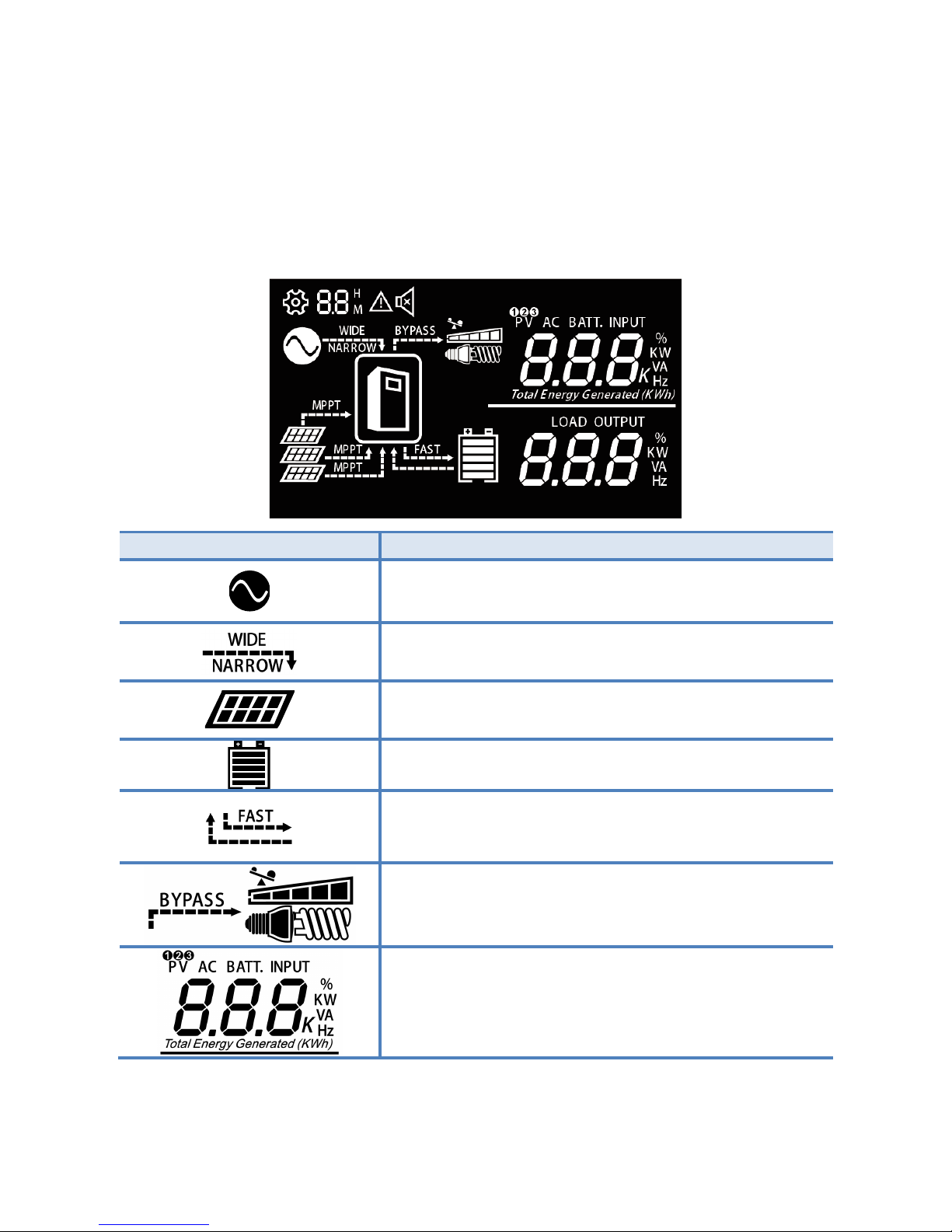
3.1 LCD display introduction
LCD displays the power flow and input/output readings in a visualized graphic
design which allows the user to understand the operation status easily.
Icon
Description
This icon is showed when AC input (from AC mains
or generator) presents.
If unit is on wide mode, “WIDE” will be lighted, else
“NARROW” will be lighted.
This icon is showed when PV (solar) system
presents.
The icon indicates level of remaining battery
capacity
The icon indicates battery flow way.
If unit is on CC & CV charging stages, “FAST” will
be lighted.
The icon indicates output load level. If unit work on
line mode, “BYPASS” will be lighted.
Indicate PV input voltage. PV input current, AC input
voltage, Battery voltage.

Indicate output voltage, output frequency, load
percentage, load VA value, load watt value.
The icon indicates unit is on LCD setting mode.
The icon indicates unit is on alarm mode or fault
mode.
When unit is on LCD setting mode, it indicates
program code.
When unit is on fault mode, it indicates the fault
code which can be referred to specific fault event
(please refer to Section “Troubleshooting”).
(2) Setting Menus
After pressing and holding button for more 2 seconds to enter setting mode,
press button for 1 second to select setting programs, then press button
to select program option, then press button to confirm the selection or
button to exit.
Program
Description
Selectable option & behavior
LCD setting display
01
AC input
voltage range
Wide (default): If selected, acceptable A
C input voltage range will be within
90-280VAC
Narrow: If selected, acceptable AC input
voltage range will be within 170-280VAC
Generator: If selected, acceptable AC
input voltage range will be within
90-280VAC
02
Output
source
priority: To
configure
load power
source
priority
Solar first(default): Solar energy provide
power to the loads as first priority.
If solar energy is not sufficient to power
all connected loads, battery energy will
supply power the load at the same time.
Utility provides power to the loads only
when any below condition happens:
-Solar energy is not available
-Battery voltage drop to either low-level
warning voltage or the setting point in
program 5.

Utility first: Utility will provide power to
the loads as first priority.
Solar and battery energy will provide
power to the load only when utility power
is not available.
SbU: Solar energy provides power to the
loads as first priority.
If solar energy is not sufficient to power
all connected loads, battery energy will
supply power the load at the same time.
Utility provides power to the loads only
when battery voltage drop to either
low-level warning voltage or the setting
point in program 5.
03
Charger
source
priority:
To configure
charger
source
priority
Solar first: Solar energy will charge
battery as first priority.
Utility will charge battery only when solar
energy is not available.
Utility first: Utility will charge battery as
first priority.
Solar energy will charge battery only
when utility power is not available.
Solar and Utility(default): Solar energy
and utility will charge battery at the same
time.
Only solar: Solar energy will be the only
charger source no matter utility is
available or not.
04
Setting
voltage point
back to
battery mode
when
selecting
"SBU priority"
or "Solar first"
in program 2.
Options in POWERBACK PB3000S
model:
Full/25.0V/25.5V/26.0V/26.5V/27.0V(def
ault)/
27.5V/28.0V.
Options in POWERBACK PB5000S
model:
Full/50V/51V/52V/53V/54V(default)/55V/
56V.
05
Setting
voltage point
back to utility
source when
selecting
"SBU priority"
or "Solar first"
in program 2.
Options in POWERBACK PB3000S
model:
21.0V/21.5V/22.0V(default)/22.5V/23.0V/
23.5V/
24.0V/24.5V.
Options in POWERBACK PB5000S
model:
42V/43V/44V(default)/45V/46V/47V/48V/
49V.
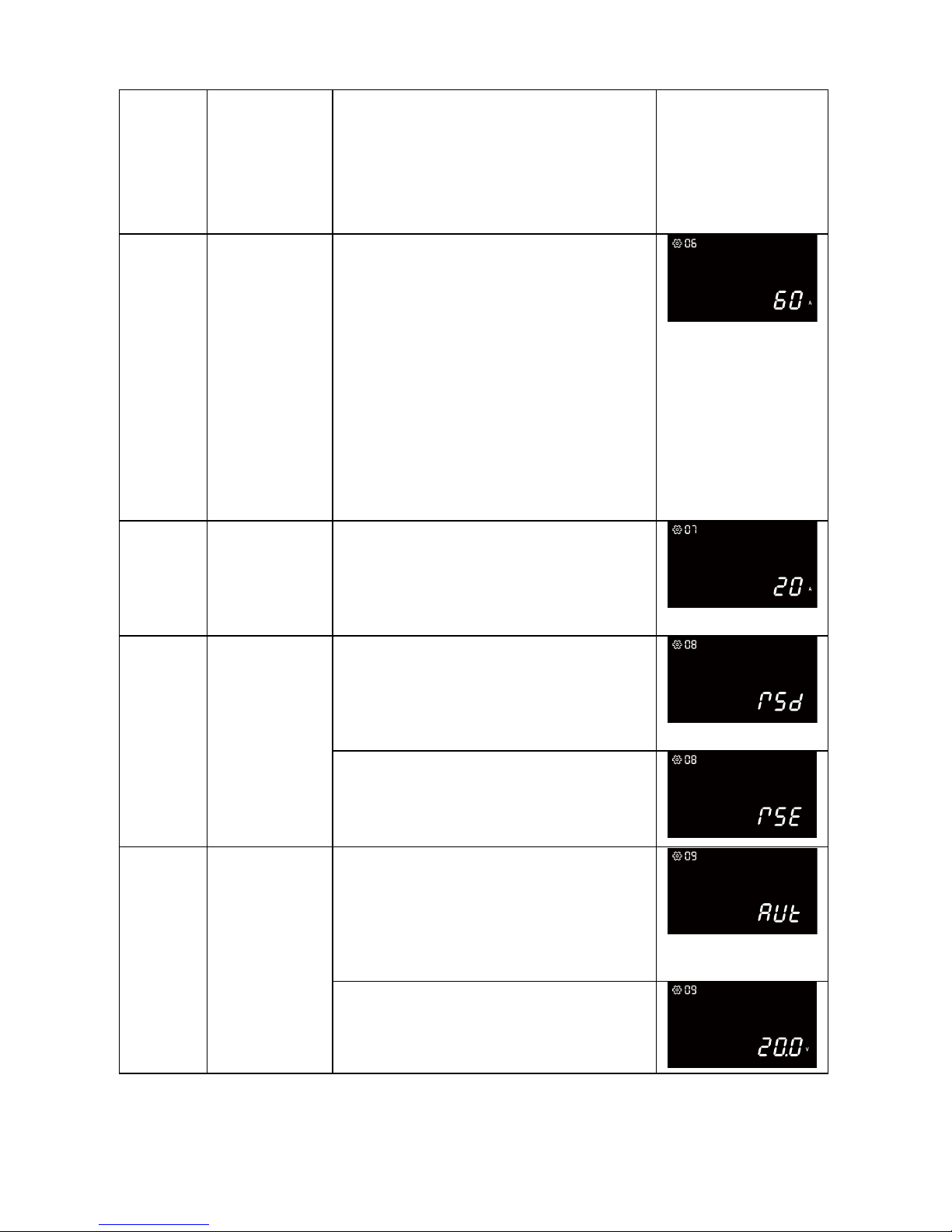
06
Max charging
current:
To configure
total charging
current for
solar and
utility
chargers:
(Max.
charging
current=utility
charging
current +solar
charging
current)
Options in POWERBACK PB3000S
model:
20A/30A/40/50A/60A(default)/70A/
80A/90A/100A
Options in POWERBACK PB5000S
model:
20A/30A/40/50A/60A(default)/70A/
80A/90A/105A
07
Max utility
charging
current
Options in POWERBACK PB3000S
model: 0A/2A/10A/20A(default)
Options in POWERBACK PB5000S
model:
0A/2A/10A/25A (default)
08
Auto restart
when
overload
occurs
Restart disable(default):
When unit is overload, unit will release
overload alarm, then turn off output &
release fault alarm, unit won’t restart
again until end-user reduce load & press
unit’s on/off power switch.
Restart enable:
When unit is overload, overload alarm 5
seconds and turn off output for 15
seconds, then restart unit again. The
restart cycle is 5 times.
09
Low DC cut
off voltage
Auto(default):
If setting auto, low DC cut off voltage will
be relate to load percent.
20.0V for 24V model @ >=60%load
21.0V for 24V model @ <60%load
40.0V for 48V model @ >=60%load
42.0V for 48V model @ <60%load
24V model:
20.0V to 24.0V, 0.2V per step;
48V model:
40.0V to 48.0V, 0.4V per step.

10
LCD backlight
control
Backlight auto(default):
LCD backlight will be off when no LCD
button is pressed after 1min.
Backlight all on
11
Recover
manufactory
setting
Recover enable:
Return to manufactory default setting.
Recover disable(default)
3.2 LCD display setting:
The default LCD display is:
Line mode
Battery mode
BAT+PV mode
The LCD display content will be changed in turns by pressing button. The
selectable information is switched as below order: PV input voltage, PV input
current, AC input voltage, battery voltage, output voltage, output frequency, load
percentage, load VA value, load watt value. LCD will return to default LCD display
after 1 minute, or press button return to default LCD display immediately.
3.3 Standby Charging Mode
The battery can be charged without switching on the inverter, and such operation
is called Standby Charging Mode. When AC input cable and battery is connected,
the inverter will enter into Standby Charging Mode and LCD will be turned on with
the following display. But if charger priority setting is only solar, utility won’t charge
battery.
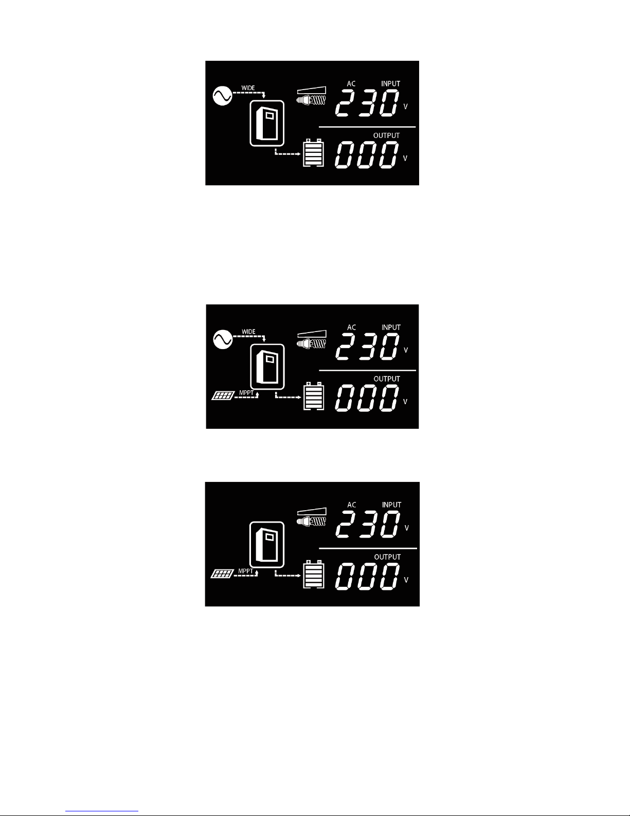
If PV string is also connected with enough voltage, the display will be as shown
below to indicate the power flow from PV string. Except only solar setting for
charger priority.
Even if AC input is absent, PV power can still charge the battery and the display
will be as shown below.
3.4 Operation Modes (after powered on)
Press the Power ON/OFF button to power on the inverter and the inverter will
automatically enter into either of the operation mode according to the condition of
AC input and PV input as shown in the table below
This manual suits for next models
1
Table of contents
Other Sollatek Inverter manuals

Popular Inverter manuals by other brands

EMP-Centauri
EMP-Centauri G1/1ECN-1 instruction manual

Huayu
Huayu HY-500-Pro Quick installation guide

Robin America
Robin America RGX3510 Service manual

ABB
ABB UNO-DM-TL-PLUS-US product manual

Zeversolar
Zeversolar Zeverlution 3680 Installation and operating instructions

GYS
GYS Greenline Inverter 5000 manual


 Instruction")


