Steri-Cult 3307 Series Operating instructions
Steri-Cult
Model 3307 and 3310 Series CO2 Incubator
Controlled RH with Sterilization Cycle
Operating and Maintenance Manual 7023307 Rev. 15

Thermo Scientific
MANUAL NUMBER 7023307
15 28727 6/18/12 Clarified nebulizer flush instructions - pg 7-4 & 7-5 ccs
14 28408 5/18/12 Chg’d 95% non-condensing in Specifications to 90% ccs
13 27891 10/27/11 Clarified Water Empty alarm language on pg 5-3 ccs
12 27292/IN-4073 9/28/11 400119 to 400201 switcher kit - pg 11-1 ccs
11 27162/IN-4071 3/24/11 Added pilasters and shelf channels to Parts Listccs
-- -- 11/24/10 Corrected typo in chart above: 3308/3310, medium/large ccs
10 25128/IN-3882 4/7/10 Missed correction from water bottle change (pgs 1-10, 7-3 & 7-4) ccs
9 25480/SI-10033 11/4/09 Common shelf channel (pg 1-7 & 1-8 artwork and 11-1 parts list) ccs
8 25128/IN-3882 9/21/09 Updated water bottle to current production (0.5 gal) ccs
7 25387/SI-10033 4/2/09 Removed soft-stops from page 1-8 ccs
Preface
7023307 Steri-Cult i
Model Size Voltage
3307 Medium 115
3308 Medium 230
3310 Large 115
3311 Large 230

Thermo Scientificii 7023307 Steri-Cult
Preface
Contains Parts and Assemblies
Susceptible to Damage by
Electrostatic Discharge (ESD)
CAUTION
Important Read this instruction manual. Failure to read, understand and follow the instructions in this manual
may result in damage to the unit, injury to operating personnel, and poor equipment performance. s
Caution All internal adjustments and maintenance must be performed by qualified service personnel. s
Caution If the incubator is not used in the manner specified in this operating manual, the protection provided
by the equipment design may be impaired. s
Material in this manual is for information purposes only. The contents and the product it describes are subject
to change without notice. Thermo Fisher Scientific makes no representations or warranties with respect to this
manual. In no event shall Thermo be held liable for any damages, direct or incidental, arising out of or related
to the use of this manual.
©2007 Thermo Fisher Scientific Inc. All rights reserved.

Thermo Scientific 7023307 Steri-Cult iii
Preface
Important operating and/or maintenance instructions. Read the accompanying text carefully.
Potential electrical hazards. Only qualified persons should perform procedures associated with this
symbol.
Equipment being maintained or serviced must be turned off and locked off to prevent possible injury.
Hot surface(s) present which may cause burns to unprotected skin, or to materials which may be
damaged by elevated temperatures.
Marking of electrical and electronic equipment, which applies to electrical and electronic equipment
falling under the irective 2002/96/EC (WEEE) and the equipment that has been put on the market
after 13 August 2005.
This product is required to comply with the European Union’s Waste Electrical & Electronic
Equipment (WEEE) irective 2002/96/EC. It is marked with the WEEE symbol. Thermo Fisher
Scientific has contracted with one or more recycling/disposal companies in each EU Member State
European Country, and this product should be disposed of or recycled through them. Further
information on Thermo’s compliance with this directive, the recyclers in your country and
information on Thermo Scientific products will be available at www.thermofisher.com.
4Always use the proper protective equipment (clothing, gloves, goggles, etc.)
4Always dissipate extreme cold or heat and wear protective clothing.
4Always follow good hygiene practices.
4Each individual is responsible for his or her own safety.

Thermo Scientificiv 7023307 Steri-Cult
Preface
Do You Need Information or Assistance on
Thermo Scientific Products?
If you do, please contact us 8:00 a.m. to 6:00 p.m. (Eastern Time) at:
1-740-373-4763 Direct
1-800-438-4851 Toll Free, U.S. and Canada
1-877-213-8051 FAX
http://www.thermoscientific.com Internet Worldwide Web Home Page
service.led.marietta@thermofisher.com Tech Support Email Address
Certified Service Web Page
Thermo Fisher Scientific
401 Millcreek Road, Box 649
Marietta, OH 45750
Our staff can provide information on pricing and give you quotations. We can
take your order and provide delivery information on major equipment items or make
arrangements to have your local sales representative contact you. Our products are listed on the
Internet and we can be contacted through our Internet home page.
Our staff can supply technical information about proper setup, operation or
troubleshooting of your equipment. We can fill your needs for spare or replacement parts or
provide you with on-site service. We can also provide you with a quotation on our Extended
Warranty for your Thermo Scientific products.
Whatever Thermo Scientific products you need or use, we will be happy to discuss your
applications. If you are experiencing technical problems, working together, we will help you
locate the problem and, chances are, correct it yourself...over the telephone without a service
call.
When more extensive service is necessary, we will assist you with direct factory trained
technicians or a qualified service organization for on-the-spot repair. If your service need is
covered by the warranty, we will arrange for the unit to be repaired at our expense and to your
satisfaction.
Regardless of your needs, our professional telephone technicians are available to assist you
Monday through Friday from 8:00 a.m. to 6:00 p.m. Eastern Time. Please contact us by
telephone or fax. If you wish to write, our mailing address is:
International customers, please contact your local Thermo Scientific distributor.
Sales Support
Service Support
www.unitylabservices.com

Thermo Scientific 7023307 Steri-Cult v
Preface
Warranty Notes
Information You Should Know Before Requesting Warranty Service
•Locate the model and serial numbers. A serial tag is located on the unit itself.
• For equipment service or maintenance, or with technical or special application inquiries, contact Technical
Services at 1-800-438-4851 or 1-740-373-4763 (USA and Canada). Outside the USA, contact your local
distributor.
Repairs NOT Covered Under Warranty
• Calibration of control parameters. Nominal calibrations are performed at the factory; typically ±1°C for
temperature, ±1% for gases, and ±5% for humidity. Our service personnel can provide precise calibrations as
a billable service at your location. Calibration after a warranty repair is covered under the warranty.
• Damage resulting from use of improper quality water, chemicals or cleaning agents detrimental to
equipment materials.
• Service calls for improper installation or operating instructions. Corrections to any of the following
are billable services:
1) electrical service connection
2) tubing connections
3) gas regulators
4) gas tanks
5) unit leveling
6) room ventilation
7) adverse ambient temperature fluctuations
8) any repair external to the unit
• Damage resulting from accident, alteration, misuse, abuse, fire, flood, acts of God, or improper
installation.
• Repairs to parts or systems resulting from unauthorized unit modifications.
• Any labor costs other than that specified during the parts and labor warranty period, which may
include additional warranty on CO2sensors, blower motors, water jackets, etc.


7023307 Steri-Cult viThermo Scientific
Table of Contents
Installation and Start-Up . . . . . . . . . . . . . . . . . . . . . . . . . . . . . . . . . . . . . .1-1
Inventory Management System . . . . . . . . . . . . . . . . . . . . . . . . . . . . .1-2
Control Panels Keys, isplays & Indicators . . . . . . . . . . . . . . . . . . . .1-2
Operation of the Keypad . . . . . . . . . . . . . . . . . . . . . . . . . . . . . . . . . .1-3
isplays . . . . . . . . . . . . . . . . . . . . . . . . . . . . . . . . . . . . . . . . . . . . . . .1-5
Installing the Incubator . . . . . . . . . . . . . . . . . . . . . . . . . . . . . . . . . . .1-5
Stacking the Incubators . . . . . . . . . . . . . . . . . . . . . . . . . . . . . . . . . .1-6
Preliminary Cleaning . . . . . . . . . . . . . . . . . . . . . . . . . . . . . . . . . . .1-7
Installing the Shelves . . . . . . . . . . . . . . . . . . . . . . . . . . . . . . . . . . . .1-7
Installing the Access Port Filter Assembly . . . . . . . . . . . . . . . . . . . .1-8
Installing the HEPA Filter . . . . . . . . . . . . . . . . . . . . . . . . . . . . . . . .1-9
Leveling the Unit . . . . . . . . . . . . . . . . . . . . . . . . . . . . . . . . . . . . .1-10
Connecting the Unit to Electrical Power . . . . . . . . . . . . . . . . . . . .1-10
Filling the Humidity Water Bottle . . . . . . . . . . . . . . . . . . . . . . . .1-10
Connecting the CO2Gas Supply . . . . . . . . . . . . . . . . . . . . . . . . .1-11
Humidity and Loading the Chamber . . . . . . . . . . . . . . . . . . . . . .1-12
Incubator Settings . . . . . . . . . . . . . . . . . . . . . . . . . . . . . . . . . . . . . . . . . . . .2-1
Setting the Temperature Setpoint . . . . . . . . . . . . . . . . . . . . . . . . . . . .2-1
Setting the Overtemp Setpoint . . . . . . . . . . . . . . . . . . . . . . . . . . . . . .2-2
Setting the CO2Setpoint . . . . . . . . . . . . . . . . . . . . . . . . . . . . . . . . . .2-3
Setting the Relative Humidity (RH) Setpoint . . . . . . . . . . . . . . . . . .2-3
Calibration . . . . . . . . . . . . . . . . . . . . . . . . . . . . . . . . . . . . . . . . . . . . . . . . . .3-1
Calibrating the Temperature . . . . . . . . . . . . . . . . . . . . . . . . . . . . . . . .3-1
Calibrating the Infrared CO2System . . . . . . . . . . . . . . . . . . . . . . . . .3-2
Calibrating Relative Humidity (RH) . . . . . . . . . . . . . . . . . . . . . . . . .3-3
Section 1
Section 2
Section 3

vii 7023307 Steri-Cult Thermo Scientific
Configuration . . . . . . . . . . . . . . . . . . . . . . . . . . . . . . . . . . . . . . . . . . . . . . . .4-1
Turning the Audible Alarm ON/OFF . . . . . . . . . . . . . . . . . . . . . . . .4-1
New HEPA Filter . . . . . . . . . . . . . . . . . . . . . . . . . . . . . . . . . . . . . . . .4-1
Setting the REPLACE HEPA Filter Reminder . . . . . . . . . . . . . . . . . .4-2
Setting an Access Code . . . . . . . . . . . . . . . . . . . . . . . . . . . . . . . . . . . .4-2
Setting a Low Temp Alarm Limit . . . . . . . . . . . . . . . . . . . . . . . . . . .4-3
Enabling Temp Alarms to Trip Contacts . . . . . . . . . . . . . . . . . . . . . .4-3
Setting a Low CO2Alarm Limit . . . . . . . . . . . . . . . . . . . . . . . . . . . .4-4
Setting a High CO2Alarm Limit . . . . . . . . . . . . . . . . . . . . . . . . . . . .4-4
Enabling CO2Alarms to Trip Contacts . . . . . . . . . . . . . . . . . . . . . . .4-5
Setting a Low RH Alarm Limit . . . . . . . . . . . . . . . . . . . . . . . . . . . . .4-5
Setting a High RH Alarm Limit . . . . . . . . . . . . . . . . . . . . . . . . . . . . .4-6
Enabling RH Alarms to Trip Contacts . . . . . . . . . . . . . . . . . . . . . . . .4-6
Selecting a Primary Tank . . . . . . . . . . . . . . . . . . . . . . . . . . . . . . . . . .4-7
isabling the Gas Guard System . . . . . . . . . . . . . . . . . . . . . . . . . . . .4-7
Setting a RS485 Communications Address . . . . . . . . . . . . . . . . . . . .4-8
Alarms . . . . . . . . . . . . . . . . . . . . . . . . . . . . . . . . . . . . . . . . . . . . . . . . . . . . . .5-1
Temp Controller Failure TEMP CNTRL ERROR . . . . . . . . . . . . . .5-2
RH System Fault . . . . . . . . . . . . . . . . . . . . . . . . . . . . . . . . . . . . . . . .5-2
Sensor Fault Alarms . . . . . . . . . . . . . . . . . . . . . . . . . . . . . . . . . . . . . .5-2
Gas Guard Alarms . . . . . . . . . . . . . . . . . . . . . . . . . . . . . . . . . . . . . . .5-2
Water Level Alarms . . . . . . . . . . . . . . . . . . . . . . . . . . . . . . . . . . . . . .5-3
oor Open Alarm . . . . . . . . . . . . . . . . . . . . . . . . . . . . . . . . . . . . . . .5-3
Troubleshooting . . . . . . . . . . . . . . . . . . . . . . . . . . . . . . . . . . . . . . . . . . . . . .6-1
Routine aintenance . . . . . . . . . . . . . . . . . . . . . . . . . . . . . . . . . . . . . . . . .7-1
Cleaning the Incubator Interior . . . . . . . . . . . . . . . . . . . . . . . . . . . . .7-1
Cleaning the Humidity System . . . . . . . . . . . . . . . . . . . . . . . . . . . . .7-2
Cleaning the Cabinet Exterior . . . . . . . . . . . . . . . . . . . . . . . . . . . . . .7-2
Flushing the Humidity System . . . . . . . . . . . . . . . . . . . . . . . . . . . .7-4
HEPA Filter Maintenance . . . . . . . . . . . . . . . . . . . . . . . . . . . . . . . . .7-
Sterilization Cycle . . . . . . . . . . . . . . . . . . . . . . . . . . . . . . . . . . . . . . . . . . . .8-1
Table of Contents
Section 4
Section 5
Section 6
Section 8
Section 7

Factory Installed Options . . . . . . . . . . . . . . . . . . . . . . . . . . . . . . . . . . . . . .9-1
Remote Alarm Contacts . . . . . . . . . . . . . . . . . . . . . . . . . . . . . . . . . . .9-1
RS485 Interface . . . . . . . . . . . . . . . . . . . . . . . . . . . . . . . . . . . . . . . . .9-2
Connecting the Analog Output Boards . . . . . . . . . . . . . . . . . . . . . . .9-3
CO2Gas Guard . . . . . . . . . . . . . . . . . . . . . . . . . . . . . . . . . . . . . . . . .9-5
Operation of the CO2Gas Guard . . . . . . . . . . . . . . . . . . . . . . . . . .9-5
e-activating the Gas Guard . . . . . . . . . . . . . . . . . . . . . . . . . . . . . .9-5
Connecting the CO2Gas Supplies . . . . . . . . . . . . . . . . . . . . . . . . .9-5
ataloggger . . . . . . . . . . . . . . . . . . . . . . . . . . . . . . . . . . . . . . . . . . . .9-6
Specifications . . . . . . . . . . . . . . . . . . . . . . . . . . . . . . . . . . . . . . . . . . . . . .10-1
Servicing . . . . . . . . . . . . . . . . . . . . . . . . . . . . . . . . . . . . . . . . . . . . . . . . . . .11-1
Parts List . . . . . . . . . . . . . . . . . . . . . . . . . . . . . . . . . . . . . . . . . . . . .11-1
Replacing the Fuses . . . . . . . . . . . . . . . . . . . . . . . . . . . . . . . . . . . . .11-3
Replacing the CO2and RH Air Filters . . . . . . . . . . . . . . . . . . . . . . .11-3
Exploded Parts rawings . . . . . . . . . . . . . . . . . . . . . . . . . . . . . . . . .11-5
Wiring iagrams . . . . . . . . . . . . . . . . . . . . . . . . . . . . . . . . . . . . . . .11-8
Electrical Schematics . . . . . . . . . . . . . . . . . . . . . . . . . . . . . . . . . . .11-10
7023307 Steri-Cult viiiThermo Scientific
Table of Contents
Section 9
Section 10
Section 11

7023307 Steri-Cult 1-1Thermo Scientific
Section 1 Installation and Start-Up
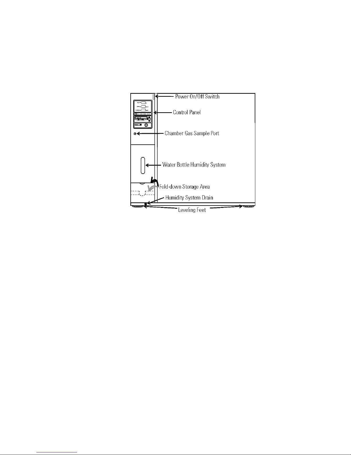
The incubator’s major components are described below.
• Chamber Gas Sample Port - Used for sampling chamber CO2content
using a FYRITE or similar instrument.
• Power On/Off Switch - Mains disconnect
• Control Panel - Keypad, isplays & Indicators (Figure 1-3)
• Fold-down Storage Area - Store manuals, markers, etc.
• Leveling Feet - Used to level the unit
Note The incubators are stackable. Information follows in this section.
Figure 1-1. Steri-Cult Components

1-2 7023307 Steri-Cult Thermo Scientific
Section 1
Installation and Start-Up
Included in the parts bag shipped with each unit is an inventory
management system. This system consists of:
• A steel plate
• Five different colored magnets
• Five heat-resistant shelf labels
• ry-Erase marker
Hang the plate on the inside of the outer
door, using the keyholes and hardware already
installed on the door. Attach a colored shelf
label to the front edge of each shelf. The
magnets may be aligned on the plate, in order
according to shelf label color. Use the marker
to record information about the product on
corresponding shelves. The magnets can be
erased as needed and rewritten.
Caution The inventory management system magnet plate will not
withstand the heat of the sterilization cycle. Simply unhook the whole
plate from the outer door and set aside before initiating the cycle, then
reinstall afterward. s
Figure 1-2. Inventory System
Inventory
anagement System
Control Panels Keys,
Displays & Indicators
Figure 1-3. Control Panel Components

7023307 Steri-Cult 1-3Thermo Scientific
Section 1
Installation and Start-Up
Silence - Silences the audible alarm.
Alarm indicator - Light pulses on/off during an alarm condition in the
cabinet.
Mode select switc - Used to select Run, Setpoints, Calibration and
System Configuration Modes.
Message center - isplays system status.
Mode select indicators -
Run: Run Menu
Settings: Set Points Menu
Calibrate: Calibration Menu
Configuration: Configuration Menu
Up / down arrows - Increments number values, toggles between choices.
Enter - Stores the value into computer memory.
Heat indicator - Lights when power is applied to the heaters.
Heat display - isplays temperature (°C)
Humidity indicator - Lights when humidity is required
RH display - isplays humidity (%)
Left and rig t arrows - Moves the operator through the choices of the
selected mode.
Inject indicator - Lights when CO2is being injected into the incubator
chamber.
CO2display - isplays CO2(%)
Sterilization button - Starts Sterilization Cycle
The Steri-Cult incubator has four basic modes which allow incubator
setup: Run, Settings, Calibrate and System Configuration.
Run is the default mode which the incubator will normally be in during
operation.
Settings is used to enter system setpoints for incubator operation.
Calibrate is used to calibrate various system parameters.
Configuration allows for custom setup of various options.
Control Panel
(continued)
Operation of the
Keypad

The chart below shows the selections under each of the Modes. Base Unit
Displays are in bold type and Option Displays are in italics.
Rig t and Left Arrows: Steps the operator through the parameters of
Settings, Calibrate and Configuration Modes. The right arrow goes to the
next parameter, the left arrow returns to the previous parameter.
Up Arrow: Increases or toggles the parameter value that has been selected
in the Settings, Calibrate, and Configuration Modes.
Enter: Must press Enter key to save to memory all changed values.
Down Arrow: ecreases or toggles the parameter values that have been
selected in the Settings, Calibrate and Configuration Modes.
Silence Key: Press to silence the audible alarm. See Section 5 for alarm
ringback times.
1-4 7023307 Steri-Cult Thermo Scientific
Section 1
Installation and Start-Up
Keypad (continued)
Run Settings Calibrate Configure
Default Temperature Temp Cal Audible
Overtemp CO2 Cal New HEPA Timer
CO2 RH Cal Replace HEPA Reminder
RH Access Code
Temp Lo Alarm
Temp Relay
CO2 Lo Alarm
CO2 Hi Alarm
CO2 Relay
RH Lo Alarm
RH Hi Alarm
RH Relay
Tank Select
Gas Guard
RS485 Address

Message Center: isplays the system status (Mode) at all times. isplays
CLASS 100, SYSTEM OK or RH WAITS ON TEMP (see Setting the
RH Setpoint for further details) during normal operation. Alarm messages
display if the system detects an alarm condition. See Section 5, Alarms.
The display message CLASS 100 is a timing mechanism indicating that,
under normal operating conditions with the HEPA filter installed, the air
inside the chamber meets the Class 100 air cleanliness standard for
particulates of 0.5 micron size or larger per cubic foot of air. (For further
information on the Class 100 classification of air quality, see Appendix A.)
3 Upper Displays: The first upper display shows the temperature. The
second display shows the percentage of CO2. The third display shows the
humidity percentage.
Caution Single and stacked units must be installed against a wall or similar
structure. s
1. Maintain a three-inch clearance behind the incubator for electrical and
gas hook-ups. In addition, a three-inch ventilation space is needed on
each side of the unit.
2. Locate the unit on a firm level surface capable of supporting the unit’s
weight (340 lbs.-Models 3307 & 3308, 410 lbs.-Models 3310 &
3311).
3. Locate the unit away from doors and windows and heating and air
conditioning ducts.
Caution Lift the unit only by the sides of the cabinet base. o not attempt
to lift by the front and back. This places stress on the outer door hinges. s
7023307 Steri-Cult 1-5Thermo Scientific
Section 1
Installation and Start-Up
Displays
Installing the
Incubator

Warning With incubators in a stacked configuration, do not leave both
exterior doors open at the same time. s
Warning If the units have been in operation, turn them both off and
disconnect the power before beginning any service work. s
Four stacking brackets (one shown at right) are included
in the parts bag shipped with each incubator.
1. Unscrew and remove the 4 leveling feet from the unit
to be stacked on top and lift it onto the base unit.
Align all sides.
Warning This incubator weighs 340 lbs. for Models 3307 & 3308, 410 lbs.
for Models 3310 & 3311. Have sufficient personnel available when lifting.
Lift the unit by the sides of the cabinet base to avoid placing stress on the
outer door hinge. s
2. Remove the hole plugs from the stacking bracket holes (Figure 1-6).
3. Align the holes in the brackets with the
mounting holes on the sides of the top and
bottom incubator. Secure the two brackets with
the stainless steel screws and washers provided in
the parts bag. See Figure 1-5.
4. The stacked incubators are ready for service.
1-6 7023307 Steri-Cult Thermo Scientific
Section 1
Installation and Start-Up
Stacking the Incubators
Figure 1-4.
Stacking Bracket
Figure 1-5. Stacking
Brackets Installed
Figure 1-6. Sides and Back of Stacked Units
Installing the Shelves
Using a suitable laboratory disinfectant, thoroughly clean all interior
surfaces.
Caution Before using any cleaning or decontamination method except
those recommended by the manufacturer, users should check with the
manufacturer that the proposed method will not damage the equipment.
Accidental spills of hazardous materials on or inside this unit are the
responsibility of the user. s
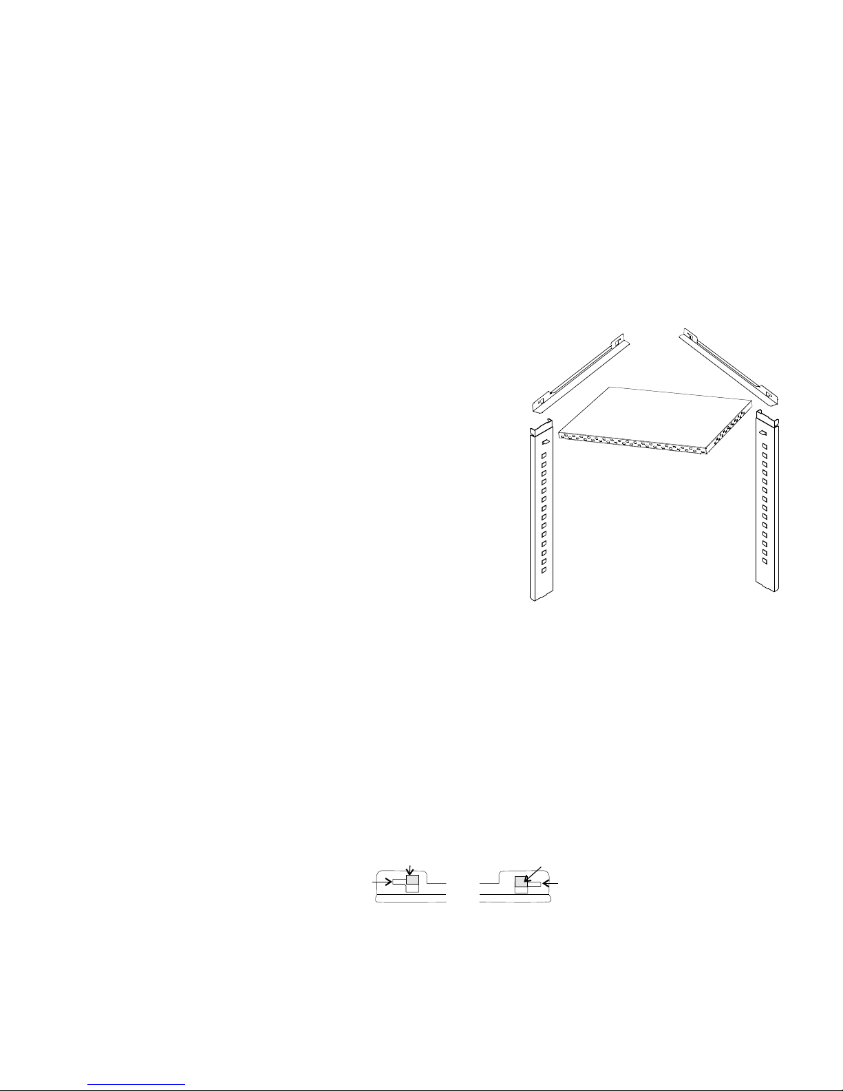
1. Install the pilasters, two on
each side, with the tab
facing into the center of the
chamber with their slots up.
Press downward on the top
section of each pilaster to
locate, then release when in
position (Figure 1-9). Fit
each pilaster securely into
the indentations at each
side of the ceiling and the
floor of the chamber. Figure
1-7 shows the diffuser pan,
pilasters, and shelf channels.
2. Install the diffuser pan in
the bottom of the unit with
the flanges down. See Section
9 at this point if your unit
includes a factory-installed
datalogger (P/N 201912).
3. Install the shelf channels by placing the channel’s rear slot over the
appropriate rear tab on the pilaster. Pull the shelf channel forward and
engage the channel’s front slot into the pilaster’s appropriate forward
tab. Refer to Figure 1-8.
7023307 Steri-Cult 1-7Thermo Scientific
Section 1
Installation and Start-Up
Preliminary Cleaning
Pilaster
Shelf Channels
Diffuser Pan
Side
toward
pilaster
Side
toward
pilaster
Pilaster
Figure 1-7. Shelf Installation
Figure 1-8. Slots and Tabs
Side duct
tab
Shelf channel
rear slot Shelf channel
front slot
Side duct
tab
FRONT

4. Figure 1-9 shows a shelf channel installed on pilasters on the right side
of the chamber.
5. Slide the shelves in, side flanges upward, along the channels into the
chamber.
1. Locate the opening in the top left corner on the inside of the chamber.
Remove the tape covering the opening on the outside of the unit.
2. Install the the filter/stopper assembly into the opening inside the
chamber. See Figure 1-10.
Caution Filter MUST be installed inside the chamber or it will become
plugged with condensation and inhibit the recovery of the RH system. o
not replace this filter with a solid cover of any kind. s
1-8 7023307 Steri-Cult Thermo Scientific
Section 1
Installation and Start-Up
Detail
Figure 1-9. Installed Shelf Channel
Installing the Access Port
Filter Assembly
Figure 1-10. Access Port Filter Installation
Installing the Shelves
(continued)

Caution Use care when handling the filter. The media can be damaged if it
is mishandled. To avoid damage to the incubator, do not operate the unit
without the HEPA filter in place. s
1. Remove the filter from the shipping box.
2. Remove the plastic covering from the filter, using caution not to touch
the filter media.
3. Loosen black wingnuts in front corners of the chamber ceiling (Figure
1-11/1-12).
4. Locate the metal lip at the upper back of the chamber. Hook the
HEPA filter carefully over the back edge of the metal lip.
5. Lift the front of the filter to the ceiling of the chamber. Push filter
bracket back over the filter frame. Tighten the wingnuts.
6. Refer to Section 6 for HEPA filter maintenance.
7023307 Steri-Cult 1-9Thermo Scientific
Section 1
Installation and Start-Up
Installing the HEPA Filter
Figure 1-11. EPA Orientation for Model 3307/3308
Figure 1-12. EPA Orientation for Model 3310/3311
This manual suits for next models
1
Table of contents


