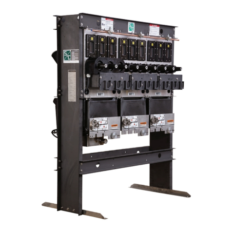
S&C Vista Owner's manual

Instruction Sheet 681-515
Introduction
Qualified Persons ..............................2
Read this Instruction Sheet.......................2
Retain this Instruction Sheet......................2
Warranty .....................................2
Safety Information
Understanding Safety-Alert Messages ..............3
Following Safety Instructions .....................3
Replacement Instructions and Labels...............3
Location of Safety Labels ........................4
Description
General ......................................5
Programming .................................5
Power and Sensing.............................6
Time-Current Characteristics .....................6
Settings ......................................6
Event Recording ...............................7
Self Testing ...................................7
Single-Pole or Three-Pole Tripping .................7
Setting Up for Programming
in the Field
Connecting a Personal Computer..................8
Setting the Communication Parameters .............8
Setting Up for Programming
in the Shop
Electronics and Burden Board ....................9
Removing the Electronics Module .................9
Connecting a Personal Computer.................11
Setting the Communication Parameters ............11
Reinstalling the Electronics Module ...............12
Programming
Factory-Default Settings ........................14
Fault Interrupters 1 and 2 .......................14
Passwords. . . . . . . . . . . . . . . . . . . . . . . . . . . . . . . . . . . 14
Main Menu ..................................14
View Menu 1 or 2 .............................15
Configure Menu 1 or 2 .........................17
Change User Password ........................19
Group Configure Menu .........................19
Test Trip Menu................................21
Self-Test Report
Viewing of Self-Test Report .....................22
Response to Self-Test Failure ....................22
Self-Test Failures and Warnings ..................23
Specifications
Port Power ..................................24
CT Power ...................................24
Steady State Accuracy .........................24
Time-Overcurrent Pickup Accuracy................24
Time-Overcurrent Response.....................24
Instantaneous Pickup Accuracy ..................24
Instantaneous Response .......................24
Definite-Time Response ........................24
Appendix A
External Connections..........................25
Appendix B
Communication Parameters .....................29
Appendix C
Using Terminal Emulator Programs................30
HyperTerminal. . . . . . . . . . . . . . . . . . . . . . . . . . . . . . . . 31
AcSELerator®QuickSet 5030™ ..................31
Appendix D
Coordination .................................32
Appendix E
Overcurrent Control Settings.....................37
Programming S&C Overcurrent Control
Section Page Section Page
Table of Contents
S&C Vista®Underground Distribution Switchgear
Undercover™, Vault-Mounted, and Pad-Mounted Styles
© S&C Electric Company 2000-2015, all rights reserved
June 1, 2015
Qualified Persons WARNING
The equipment covered by this publication must be operated and maintained by qualified
persons who understand any hazards involved and are thoroughly trained in the operation
and maintenance of electronic control devices which are used in conjunction with power dis-
tribution equipment. These instructions are intended only for such qualified persons. They
are not intended to be a substitute for adequate training and experience in safety proce-
dures for this type of equipment.
Read this
Instruction Sheet
Thoroughly and carefully read this instruction sheet before programming, operating,
or maintaining your S&C Overcurrent Control. Familiarize yourself with the safety
information on page 3. The latest version of this instruction sheet is available online in
PDF format at sandc.com/Support/Product-Literature.asp
Retain this
Instruction Sheet
This instruction sheet is a permanent part of your S&C Vista Underground Distribu-
tion Switchgear. Designate a location where you can easily retrieve and refer to this
publication.
Warranty The warranty and/or obligations described in S&C’s standard conditions of sale, as
set forth in Price Sheet 150, plus any special warranty provisions, as set forth in the
applicable product-line specication bulletin, are exclusive. The remedies provided in the
former for breach of these warranties shall constitute immediate purchaser’s or end user’s
exclusive remedy and a fulllment of all seller’s liability. In no event shall seller’s liability
to immediate purchaser or end user exceed the price of the specic product which gives
rise to immediate purchaser’s or end user’s claim. All other warranties whether express
or implied or arising by operation of law, course of dealing, usage of trade or otherwise,
are excluded. The only warranties are those stated in Price Sheet 150, and THERE ARE
NO EXPRESS OR IMPLIED WARRANTIES OF MERCHANTABILITY OR FITNESS FOR
A PARTICULAR PURPOSE. ANY EXPRESS WARRANTY OR OTHER OBLIGATION
PROVIDED IN PRICE SHEET 150 IS GRANTED ONLY TO THE IMMEDIATE PURCHASER
AND END USER, AS DEFINED THEREIN. OTHER THAN AN END USER, NO REMOTE
PURCHASER MAY RELY ON ANY AFFIRMATION OF FACT OR PROMISE THAT
RELATES TO THE GOODS DESCRIBED HEREIN, ANY DESCRIPTION THAT RELATES
TO THE GOODS, OR ANY REMEDIAL PROMISE INCLUDED IN PRICE SHEET 150.
Introduction
2 S&C Instruction Sheet 681-515

Understanding
Safety-Alert
Messages
There are several types of safety-alert messages which may appear throughout this
instruction sheet as well as on labels attached to the S&C Overcurrent Control. Famil-
iarize yourself with these types of messages and the importance of the various signal
words, as explained below.
DANGER
“DANGER” identifies the most serious and immediate hazards which will likely
result in serious personal injury or death if instructions, including recommended pre-
cautions, are not followed.
WARNING
“WARNING” identifies hazards or unsafe practices which can result in serious per-
sonal injury or death if instructions, including recommended precautions, are
not followed.
CAUTION
“CAUTION” identifies hazards or unsafe practices which can result in minor
personal injury or product or property damage if instructions, including recommended
precautions, are not followed.
NOTICE
“NOTICE” identifies important procedures or requirements that, if not followed, can result in
product or property damage if instructions are not followed.
Following Safety
Instructions
If you do not understand any portion of this instruction sheet and need assistance,
contact your nearest S&C Sales Ofce or S&C Authorized Distributor. Their tele-
phone numbers are listed on S&C’s website sandc.com Or call S&C Headquarters
at (773) 338-1000; in Canada, call S&C Electric Canada Ltd. at (416) 249-9171.
NOTICE
Thoroughly and carefully read this
instruction sheet before programming
your S&C Overcurrent Control.
Replacement
Instructions
and Labels
If you need additional copies of this instruction sheet, contact your nearest S&C Sales
Ofce, S&C Headquarters, or S&C Electric Canada Ltd.
It is important that any missing, damaged, or faded labels on the equipment be
replaced immediately. Replacement labels are available by contacting your nearest S&C
Sales Office, S&C Headquarters, or S&C Electric Canada Ltd.
Safety Information
S&C Instruction Sheet 681-515 3

Location of Safety Labels
Enclosure for overcurrent control with cover removed to show electronics module.
Electronics module
WARNING
Hazardous voltage inside can shock, burn,
or cause death.
Safety Information
DANGER
Never disconnect current transformer
secondary circuits without de-energizing
the switchgear. Hazardous voltage will
shock, burn, or cause death.
Burden-board module
Electronics module removed to show burden-board module.
4 S&C Instruction Sheet 681-515

Enclosure is mounted on switchgear in
operation compartment (Pad-Mounted and
Dry-Vault-Mounted Style shown here—a
stainless-steel enclosure is provided for
UnderCover and Wet-Vault-Mounted Style
Vista)
Adapter cable connects overcurrent
control to a personal computer
Personal computer is used to input
settings and interrogate event recorder
General The following instructions are for eld and shop programming of the S&C Overcurrent
Control. This microprocessor-based control is designed for use on S&C Vista Under-
ground Distribution Switchgear to provide fault detection and operation of the resettable,
vacuum fault interrupters. Each overcurrent control operates up to six single-pole fault
interrupters or two three-pole fault interrupters. The control is housed in an enclosure
which is mounted on the operation side of the switchgear. For UnderCover and Wet-Vault-
Mounted Style Vista units, the enclosure is fully submersible. The electronics module is
removable for programming in the shop.
Programming A personal computer furnished by the user is to be used to input settings, review set-
tings, and interrogate the event recorder. The software for programming the overcurrent
control is contained within the control. Two data ports are provided—one on the
enclosure for programming in the eld, and another on the electronics module for
programming in the shop. Adapter cables are available from S&C (see Instruction Sheet
681-515A) to connect the computer to the control.
An external power source is required for programming and interrogating the control.
A source of dc power is available from the mouse or USB port on the personal computer.
The adapter cables contain connectors for data and power to utilize the power available
from the computer.
Description
S&C Instruction Sheet 681-515 5

Power and Sensing Current transformers are provided inside the switchgear tank for each set of three single-
pole fault interrupters or each three-pole fault interrupter. These current transformers
provide primary current sensing ranging from 50 to 12,500 amperes (100 to 25,000 amperes
for 900-ampere and 1200-ampere models). Vista UDS rated above 12.5 kA short circuit
will respond to fault currents above 12.5 kA, but the event log will only record that a fault
above 12.5 kA has occurred (or 25 kA for 900-ampere and 1200-ampere models). The
overcurrent control is capable of sensing and responding to both phase overcurrents and
ground overcurrents.
The power derived from the current transformers is used to operate the control and
to charge the trip capacitors which discharge into magnetic latching solenoids to trip the
fault interrupters during a fault. No external power is required for operation of the control
in the field.
Time-Current
Characteristics
The overcurrent control features time-current characteristic (TCC) curves consisting
of phase-overcurrent curves and ground-overcurrent curves. The families of curves are
included as follows:
• S&C Standard Speed curves (for use in place of conventional “E” rated power fuses.
• S&C “K” Speed curves (for use in place of conventional “K” rated power fuses).
• Tap Fault Interrupter curves.
• Main Fault Interrupter curves.
• ANSI U.S. and IEC curves per IEEE Standard C37.112-1996 U1, U2, U3, U4, U5, C1, C2,
C3, C4, and C5.
The tap and main fault-interrupter TCC curves can be customized into hundreds
of different curves using a variety of instantaneous-pickup settings (discrete choices
from 0.2 kA through 6 kA), and definite-time delay settings (discrete choices from
32 ms through 128 ms). For even more specialized shapes, an instantaneous-pickup
setting can be combined with a definite-time delay setting. The minimum total
clearing time—from initiation of the fault to total clearing—is 40 milliseconds.▲
Settings
(See Appendix E for a
complete list of settings)
The overcurrent control has a phase-overcurrent pickup setting and an independent
ground-overcurrent pickup setting for each set of three single-pole fault interrupters or
each three-pole fault interrupter.
The input parameters for both the phase- and ground-overcurrent curves include
minimum pickup levels, instantaneous-pickup levels, and definite-time delays.
Phase-overcurrent pickup settings and ground-overcurrent pickup settings are made
independently. If desired, the ground-overcurrent curve and the instantaneous-
pickup and definite-time-delay attributes can be disabled. When E-speed or K-speed
curves are selected, the ground-overcurrent pickup setting is disabled as are the
instantaneous-pickup and definite-time-delay attributes. An example of how to select set-
tings for the overcurrent control is shown in Appendix D.
A choice of 50- or 60-hertz operation are also offered. For single-pole fault interrupters,
a choice of single-pole or three-pole trip is also offered (single-pole tripping is not possible
with three-pole fault interrupters).
▲The definite-time delay setting will override the instantaneous setting when the definite-time delay setting is activated before the instantaneous
setting.
Description
6 S&C Instruction Sheet 681-515

Event Recording The overcurrent control features an internal event recorder that captures the last
twelve fault operations for each fault interrupter. The event log indicates which poles
have experienced a fault, the magnitude of the fault, and whether or not a ground
overcurrent was involved. This information can be accessed via a personal computer
connected to the data port of the control.
Self Testing Whenever the overcurrent control is powered up—and then periodically thereaf-
ter—it automatically goes through a self-test procedure to test vital subsystems and
ensure proper operation. The control checks the trip capacitors, power-supply volt-
age, RAM, EEPROM, integrity of the data, and voltage control. It then ags whatever
fails the self-test.
Single-Pole or
Three-Pole Tripping
Three-pole fault interrupters are factory-programmed for three-pole tripping. This
setting should not be changed since single-pole tripping is not possible with three-
pole fault interrupters. However, when used with single-pole fault interrupters, the
overcurrent control can be programmed for either single-pole or three-pole tripping
of the fault interrupters. Single-pole tripping operation is when the control trips
only those fault interrupters on the phases that have experienced a fault. When set
for single-pole tripping operation, the control will not trip the fault interrupters in
response to a ground fault, but will respond to a phase overcurrent—whether or not
it involves ground.
Three-pole tripping operation is when the control trips all three fault interrupters
regardless of which phase has experienced a fault. For three-pole tripping operation,
a ground-fault setting is available and the control will operate the fault interrupters
in response to a ground overcurrent.
Description
S&C Instruction Sheet 681-515 7

Connecting a Personal Computer
A data port for communications is provided at the top of
the enclosure that houses the overcurrent control. This
data port, which is connected to the electronics module
inside the enclosure, cannot draw power from the control
and must be powered from an external source while in
use. When the data port is in use, the power-connection
points (Pins 1 and 4) power the control. The allowable
voltage range is 4 – 5 Vdc, and the power consumption is
1.8 W nominal, 2.2 W maximum.
Adapter cables are available from S&C (see Instruction
Sheet 681-515A) for connecting the control to a user-furnished
personal computer in the field. These cables provide for both
communications and power.
For Microsoft Windows users, no special software is
required to communicate with the control. The user interface
is menu driven within the control. Use the HyperTerminal
program provided with Microsoft Windows or other terminal
emulator program to set or interrogate the control.
Microsoft Windows Vista™, Windows®7, and Windows®8
users will have to install a terminal emulator program. See
Appendix C for further instructions.
Setting the Communication Parameters
Set the communication parameters shown in Appendix B.
Refer to Appendix C for additional instructions regarding
terminal emulation programs.
Adapter cable—connect cable to personal
computer (USB Style cable not shown)
Overcurrent control—(Pad-Mounted and
Dry-Vault-Mounted Style enclosure shown)
Adapter cable—connect cable to
communications data port on enclosure
Data port
Setting Up for Programming in the Field
8 S&C Instruction Sheet 681-515

Electronics and
Burden Board DANGER
Never disconnect CT secondary circuits without de-energizing the switchgear. Hazardous
voltage will shock, burn, or cause death.
CAUTION
When the electronics module is removed from its enclosure, the associated fault interrupt-
ers will not provide fault protection
The overcurrent control consists of an electronics module and a burden-board module
(burden board and base plate). Two current transformers (CTs) are provided for each
fault-interrupter pole; one supplies measurement current for the control and the other
supplies power for the control. The burden board recties the power and also transforms
the measurement current from the CT secondaries into voltage. It then passes rectied
power and current signals to the electronics module. The burden board provides the
burden for the CTs so that the electronics module can be removed and replaced while
the Vista switchgear is energized. A grounded shield protects the user from contact with
the CT secondaries should the secondaries become disconnected from the burden board.
Removing the
Electronics Module
1. Loosen the captive screws or bolts
that secure the cover of the control’s
enclosure in place and remove the
cover.
Four captive screws
secure cover to Pad-Mounted or
Dry-Vault-Mounted Style enclosures;
22 bolts secure cover to submersible
enclosures
CAUTION
ALWAYS disconnect the trip connectors from the electronics module before removing the
module from the base plate. Failure to follow this precaution may result in the unex-
pected operation of a fault interrupter.
Trip connectors—loosen both trip connectors and remove
them from electronics module
Electronics module
2. Disconnect the two trip connectors from the front of the electronics module.
Setting Up for Programming in the Shop
S&C Instruction Sheet 681-515 9

3. Loosen the two captive screws that secure the electronics module to the base
plate.
Captive screws secure electronics
module to base plate. Loosen the two screws
to prepare for removal of electronics module
4. Grasp the electronics module by the handle and lift it upward slightly away from
the base plate. This raises the stand-off attached to the inside of the cover of the
electronics module, allowing the CT shorting clip to make its connection to the
power CT secondaries and short circuit the secondaries. After the CT secondar-
ies are short circuited, the connection between the electronics module and the
burden-board module breaks.
Blind-mate
connector
on burden
board
Stand off
Shorting
clip
Burden-board module
Blind-mate
connector on
main board
Electronics module
5. Slide the electronics module a short distance away from the rear wall of the base
plate, lift the module up, and remove it from the base plate.
Electronics module—remove electronics module
from enclosure by sliding the module
forward slightly and lifting it upward
Setting Up for Programming in the Shop
10 S&C Instruction Sheet 681-515

Connecting a Personal Computer
A data port for communications is provided at the top of
the enclosure that houses the overcurrent control. This
data port, which is connected to the electronics module
inside the enclosure, cannot draw power from the control
and must be powered from an external source while in
use. When the data port is in use, the power-connection
points (Pins 1 and 4) power the control. The allowable
voltage range is 4 – 5 Vdc, and the power consumption is
1.8 W nominal, 2.2 W maximum.
Adapter cables are available from S&C (see Instruction
Sheet 681-515A) for connecting the control to a user-furnished
personal computer in the field. These cables provide for
both communications and power.
For Microsoft Windows users, no special software
is required to communicate with the control. The
user interface is menu driven within the control. Use
the HyperTerminal program provided with Microsoft
Windows or other terminal emulator program to set or
interrogate the control. Microsoft Windows Vista,
Windows 7, and Windows 8 users will have to install a
terminal emulator program. See Appendix C for further
instructions.
Setting the Communication Parameters
Set the communication parameters shown in Appendix B.
Refer to Appendix C for additional instructions regarding
terminal emulation programs. Adapter cable—connect cable
to personal computer (USB
Style cable not shown)
Adapter cable—connect cable
to data port on electronics module
Electronics module
Data port
Setting Up for Programming in the Shop
S&C Instruction Sheet 681-515 11

Reinstalling the
Electronics Module
1. Hold the electronics module by the handle at the front of the module.
2. Place the rear of the electronics module onto the base plate of the burden-board module
while holding the front of the electronics module away from the base plate at a slight
angle. Slide the electronics module back until it engages the rear wall of the base plate.
Two slots at the back of the electronics module will engage with the tabs in the base
plate which hold the electronics module in place.
Electronics module—reinstall electronics module by
sliding it toward rear wall of base plate at a slight angle.
After module engages tabs, lower it onto the base plate
3. Lower the front of the electronics module onto the base plate. This connects the elec-
tronics module to the burden-board module. It also lowers the stand-off which pushes
the CT shorting clip away from the burden board removing the short circuit from the
power CT secondaries. The control will power up if sufcient current is owing through
the Vista switchgear.
Blind-mate connectors on main board and burden board
Stand off
Shorting
clip
Burden board
Base plate
Electronics module
Setting Up for Programming in the Shop
12 S&C Instruction Sheet 681-515

4. Tighten the two captive screws that secure the electronics module to the base plate.
Captive screws—tighten the two screws
to secure electronics module to base plate
5. Connect the two trip connectors to the front of the electronics module. The trip
connectors are keyed and cannot be swapped or installed incorrectly.
Trip connectors—fasten both trip connectors
to electronics module
6. Place the cover on the control’s enclosure and tighten the captive screws or bolts
that secure the cover in place.
Four captive screws secure cover to Pad-Mounted or Dry-Vault-
Mounted Style enclosures; 22 bolts secure cover to submersible
enclosures (tightened to 15 foot-pounds)
Setting Up for Programming in the Shop
S&C Instruction Sheet 681-515 13

Factory-Default
Settings
The overcurrent control is provided with the factory-default settings shown here.
TCC Curve Type = E
Curve Selection = 200E
Instantaneous Pickup (Amps) = NA
Definite-Time Delay (ms) = NA
Fault Interrupters 1
and 2
Each overcurrent control is capable of operating up to two fault interrupters. To
differentiate between the two fault interrupters, the programming software refers to Fault
Interrupter 1 and Fault Interrupter 2. If the control is operating two fault interrupters, the
fault interrupter to the left of the control (as you are facing the operating compartment) is
Fault Interrupter 1 and the fault interrupter to the right of the control is Fault Interrupter
2. If there is only one fault interrupter, it is Fault Interrupter 2.
Passwords Factory-Default Passwords
Type of Password
User
Group Configure
Password
6601
4731
Two passwords—the User and Group Congure Passwords—control access to the sensi-
tive areas of the menu system. The User Password must be entered to change control
settings, test trip the solenoids, and change the User Password.
The Group Configure Password is required to change the global settings, download
firmware, and change the Group Configure Password.
Passwords must contain four numeric characters. Each control is provided with
factory- default passwords. The User and Group Configure Passwords can be changed, but
the default passwords will always allow access.
Main Menu 1. To begin communications, open the terminal emulator program and press <ENTER>
(refer to Appendix C for additional instructions regarding terminal emulation). The
control will respond with the Main Menu and “=” prompt.
2. Select the desired option from the Main Menu and input the corresponding number
after the “=” prompt. Press <ENTER>. (Option 1is shown as an example.)
Main Menu: <select number>
1. View Menu 1
2. Configure Menu 1
3. View Menu 2
4. Configure Menu 2
5. Change User Password
6. Switch to Group Configure
7. Test Trip Menu
= 1
INTERRUPTER 1
INTERRUPTER 1
INTERRUPTER 2
INTERRUPTER 2
3. Refer to one of the following sections for further information:
Option Page
View Menu 1 ...................................... 15
Configure Menu 1 .................................. 17
View Menu 2 ...................................... 15
Configure Menu 2 .................................. 17
Change User Password ............................. 19
Group Configure Menu.............................. 19
Test Trip Menu..................................... 21
Programming
14 S&C Instruction Sheet 681-515

View Menu 1 or 2 The View Menu allows review of the settings and status of the control. (The View Menu
shown at right is for Fault Interrupter 1.)
1. Select the desired option from the View Menu and input the corresponding number
after the “ > ” prompt. Press <ENTER>. (Option 1is shown as an example.)
2. Refer to the appropriate subsection below for further information on the selected option.
3. To return to the Main Menu, input “9” after the “>” prompt and press <ENTER>.
View Menu INTERRUPTER 1: <select number>
1. View event report (last 12 events)
2. View load current
3. View relay settings
4. View relay self-test
9. Switch to Main Menu
= View FI 1 > 1
1. View Event Report
The View Event Report option allows viewing of the last 12 recorded events for the
selected fault interrupter. The report includes faulted poles and whether ground was
involved, primary RMS current magnitude and ground current for each pole, at the exact
instant that fault current is detected (which values may not always make sense), and the
time since the last event. The time is not displayed if there has been no other event since
power up or if more than 60 seconds has elapsed since the previous report.
New events are inserted at the number 1 position. When the list is full, the oldest event
will drop from the list. Faulted poles are indicated by an “X.”
The overcurrent control stores a nonvolatile short event report each time it issues a
trip pulse. The short event report contains the following information:
• The faulted pole(s) and whether ground was involved. The “target” (X) logic is as
follows:
1. Target any faulted poles that caused a trip.
2. Target any phase faulted pole with current greater than the phase time overcurrent
pickup setting.
INTERRUPTER 1
*Eve* **Faulted Poles** * * * * * Amperes ** * * * Elapsed
**Time**
# 1 2 3 G 1 2 3 G (Seconds)
1 X X X 4 2040 1829 1908 0.019
2 X X 24 1926 18 1908
3 X X 2010 22 18 1992
Press <ENTER> for menu
NOTE: The “X” targets are utilized under fault conditions. In test mode, fault
poles are randomly selected.
Programming
S&C Instruction Sheet 681-515 15

3. Target the ground faulted pole if ground current is greater than the ground pickup
setting or if ground current is greater than or equal to 50A and greater than 10% of the
maximum phase current.
4. If only one target is declared from the previous logic, target the faulted pole (of the
remaining three with the highest current.
The primary RMS magnitude of each pole and ground current. Current greater than
14,500 ampere will be reported as “>14500” (“>29000” for 900-ampere and 1200-ampere
models).
The event report is reset when the fault interrupter settings are changed and saved.
2. View Load Current
The View Load Current option allows viewing a snapshot of the load current sensed by
the current transformers for each pole and ground for the selected fault interrupter.
INTERRUPTER 1
123G
Load Current (Amperes) 50 49 48 2
Press <ENTER> for menu
3. View Relay Settings
The View Relay Settings option allows viewing of the time-current characteristic curve
settings, trip mode, and frequency for the selected fault interrupter.
INTERRUPTER 1
PHASE GROUND
TCC Curve Type E NA
Curve Selection 200E NA
Inst. Pickup (kA) N/A N/A
Definite-Time Delay (ms) N/A N/A
Trip Mode
Frequency
3
60
Press <ENTER> for menu
Programming
16 S&C Instruction Sheet 681-515

4. View Relay Self-Test
The View Relay Self-Test option allows viewing of the self-test status report for the
selected fault interrupter. This report includes the status of the trip capacitors, supply
voltage, RAM, integrity of the data, CR-RAM, EEPROM, and voltage control. See “SELF-
TEST REPORT” on page 23 for more information.
INTERRUPTER 1
FID = S&C–1000–R100–970317
SELF TESTS
W = Warn F = Fail
Pole # 1 2 3
Trip Caps OK OK OK
Supply + 5V + 12V
Voltage 4.99 12.26
RAM FLASH CR_RAM EEPROM V_CONTROL
OK OK OK OK OK
Press <ENTER> for menu
Configure Menu 1 or 2 The Congure Menu allows review and changes to the time-current characteristic curve
settings for the selected fault interrupter. (The Congure Menu shown at right is for Fault
Interrupter 1.)
1. Select the desired option from the Congure Menu and input the corresponding
number after the “ > ” prompt. Press <ENTER>. (Option 1is shown as an example.)
2. Refer to the appropriate subsection below for further information on the selected
option.
3. To return to the Main Menu, input “9” after the “ > ” prompt and press <ENTER>.
Configure Menu INTERRUPTER 1: <select number>
1. Change relay settings
2. View relay settings
9. Switch to Main Menu
= Config FI 1 > 1
Programming
S&C Instruction Sheet 681-515 17

1. Change Relay Settings
The Change Relay Settings option allows changes to the time-current characteristic
curve settings for the selected fault interrupter. There is a prompt for the input for each
setting.
1. After each prompt, enter the new setting and press <ENTER>. The available choices are
shown in parenthesis. To retain the previous selection shown after the “= ”, press <ENTER>.
2. After all of the settings have been entered, the new settings will be displayed in a table. Enter
“Y” for yes or “N” for no after the “Save Changes (Y/N)?” prompt. A conrmation of the choice
will be shown and the settings will be displayed. Note that when new settings are saved, the
event report discussed on page 15 will be reset.
<Press ‘Q’ to return to menu>
Phase TCC Curve (E, K, TAP, MAIN, U1, U2, U3, U4, U5, C1, C2, C3, C4, C5) = E ?tap
Minimum Pickup (Amps) (50, 65, 80, 100, 150, 200, 250, 300, 350, 400) = 50 ?200
Instantaneous Pickup (kA) (OFF, 0.2, 0.3, 0.4, 0.5, 0.6, 0.7, 0.8, 0.9, 1, 2, 3, 4, 5, 6) = OFF ?5
Denite-Time Delay (ms) @ 60Hz (OFF, 32, 48, 64, 80, 96) = OFF ?32
Ground TCC Curve (OFF, TAP, MAIN) = OFF ?tap
Minimum Pickup (Amps) (50, 65, 80, 100, 150, 200, 250, 300, 350, 400) = 50 ?200
Instantaneous Pickup (kA) (OFF, 0.2, 0.3, 0.4, 0.5, 0.6, 0.7, 0.8, 0.9, 1, 2, 3, 4, 5, 6) = OFF ?1
Denite-Time Delay (ms) @60Hz (OFF, 32, 48, 64, 80, 96) = OFF ?32
PHASE GROUND
TCC Curve Type TAP TAP
Min. Pickup (Amperes) 200 200
Inst. Pickup (kA) 5 1
Denite-Time Delay (ms) 32 32
Save Changes (Y/N)? y
SETTINGS SAVED
PHASE GROUND
TCC Curve Type TAP TAP
Min. Pickup (Amperes) 200 200
Inst. Pickup (kA) 5 1
Denite-Time Delay (ms) 32 32
Programming
18 S&C Instruction Sheet 681-515

2. View Relay Settings
The View Relay Settings option allows viewing of the current control settings for the
selected fault interrupter. The trip mode and frequency settings are included.
INTERRUPTER 1
PHASE GROUND
TCC Curve Type TAP TAP
Min. Pickup (Amperes) 200 200
Inst. Pickup (kA) 5 1
Definite-Time Delay (ms) 32 32
Trip Mode
Frequency
3
60
Press <ENTER> for menu
Change User
Password
The Change User Password option allows changing of the User Password. After the new
password has been entered, the control will return to the Main Menu.
1. Enter the current User Password after the rst prompt.
2. Enter the new password after the second prompt. The password must have four
numeric characters.
3. To conrm the new password, re-enter it after the third prompt.
USER PASSWORD: ? * * * * *
CHANGE USER PASSWORD
Enter new password (four digits, blank for no change) * * * * *
Re-enter new password * * * * *
Group Configure Menu The Group Congure option allows viewing and changing of the global settings, changing
of the Group Congure Password, and downloading of rmware.
1. Select the desired option from the Group Congure Menu and input the corresponding
number after the “ > ” prompt. Press <ENTER>. (Option 1is shown as an example.)
2. Refer to the appropriate subsection below for further information on the selected
option.
3. To return to the Main Menu, input “9” after the “ > ” prompt and press <ENTER>.
Group Configure Menu: <select number>
1. Change global settings
2. View global settings
3. Change Group Configure Password
4. Download Firmware
9. Switch to Main Menu
=Group Config > 1
Programming
S&C Instruction Sheet 681-515 19

1. Change Global Settings
The Change Global Settings option allows changing of the fault interrupter ID, trip mode,
and frequency.
CAUTION
Do not program three-pole fault interrupters to operate in single-pole trip mode. Single-pole
tripping is not possible with three-pole fault interrupters.
1. After each prompt, enter the new setting and press <ENTER>. The available choices
are shown in parenthesis. To retain the previous selection shown after the “ = ”, press
<ENTER>.
2. After all of the settings have been entered, the new settings will be displayed in a table.
Enter “Y” for yes or “N” for no after the “Save Changes (Y/N)?” prompt. A conrmation
of the choice will be shown and the settings will be displayed.
<Press ‘Q’ to return to menu>
ID for Interrupter 1 (20 characters) = INTERRUPTER 1
?interrupter pole 1
ID for Interrupter 2 (20 characters) = INTERRUPTER 2
?interrupter pole 2
1-pole or 3-pole trip mode for Interrupter 1 (1,3) = 1 ?3
1-pole or 3-pole trip mode for interrupter 2 (1, 3) = 1 ?3
50 Hz or 60 Hz Operation (50, 60) = 60 ?
ID Interrupter 1 INTERRUPTER POLE 1
ID Interrupter 2 INTERRUPTER POLE 2
Trip Mode Interrupter 1 3
Trip Mode Interrupter 2 3
Nominal Frequency 60
Save Changes (Y/N)? n
SETTINGS NOT SAVED
ID Interrupter 1 INTERRUPTER 1
ID Interrupter 2 INTERRUPTER 2
Trip Mode Interrupter 1 1
Trip Mode Interrupter 2 1
Nominal Frequency 60
2. View Global Settings
The View Global Settings option allows viewing of the global settings including the fault
interrupter ID, trip mode, and frequency.
ID Interrupter 1 INTERRUPTER 1
ID Interrupter 2 INTERRUPTER 2
Trip Mode Interrupter 1 3
Trip Mode Interrupter 2 3
Nominal Frequency
Press <ENTER> for menu
60
Programming
20 S&C Instruction Sheet 681-515
Other manuals for Vista
2
Table of contents
Other S&C Industrial Equipment manuals

S&C
S&C TripSaver II Quick guide

S&C
S&C TripSaver II User manual

S&C
S&C PMH User manual

S&C
S&C VacuFuse II User manual

S&C
S&C PME Pad-Mounted Gear User manual

S&C
S&C IntelliRupter PulseCloser R3 User manual

S&C
S&C VacuFuse User guide

S&C
S&C CS-1A User manual

S&C
S&C Vista SD 101 User manual

S&C
S&C Vista User manual