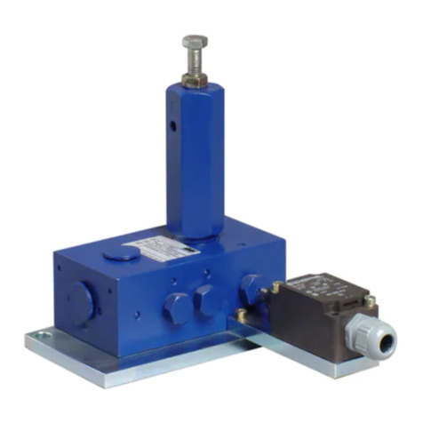
SKF 85250 Instruction Manual

User and maintenance instructions
Models and
Air operated ejector
Date of issue July
Form number
Version

Contents
Declaration of Incorporation* . . . . . . .
U.K. Declaration of Incorporation* . . .
Signal words for safety. . . . . . . . . . . . .
Safety . . . . . . . . . . . . . . . . . . . . . . . . . . .
Owner/operator manual. . . . . . . . . . . .
Before connecting ejector to air line. .
Operating precautions . . . . . . . . . . . . .
Operation . . . . . . . . . . . . . . . . . . . . . . . .
Service and disassembly procedure . .
Tools required . . . . . . . . . . . . . . . . . . . .
Disassembly of air components . . . . .
Disassembly of wetted components . .
Reassembly. . . . . . . . . . . . . . . . . . . . . . .
Adjustment procedure: . . . . . . . . . . . . . .
Warranty . . . . . . . . . . . . . . . . . . . . . . . . .
*Indicates change.

Declaration of Incorporation* DOCUMENT NUMBER
404589.DoI
Manufacturer name/address:
Lincoln Industrial Corporation
N. Hanley Road
St. Louis, MO U.S.A.
TEL: + () - FAX: + () -
Authorized to compile the technical file:
SKF Lubrication Systems Germany GmbH
Heinrich-Hertz-Straße -
Walldorf, Germany
TEL: + () -
EMAIL: robert.collins@skf.com WEBSITE: www.skf.com
This Declaration of Incorporation is issued
under sole responsibility of the
manufacturer. Lincoln Industrial Corporation
hereby declares that the partly completed
machinery stated below:
Name: Ejectors
Model number(s):
Description:
Year of CE:
in its intended use, is in conformity with the
relevant union harmonization legislation:
Machinery Directive //EC
and conforms to the following harmonized
standards:
EN ISO :
Hydraulic fluid power - General rules and
safety requirements for systems and their
components
EN ISO :
Safety of machinery. General principles
for design. Risk assessment and risk
reduction
EN ISO :+A:
Pumps and pump units for liquids -
Common safety requirements
EN ISO :
Pneumatic fluid power. General rules and
safety requirements for systems and their
components
The following EHSR (Essential Health and
Safety Requirements) have been applied:
..a – ..b – ..c – .. – .. –
.. – .. – .. – .. – .. – ..
– .. – .. – .. – . – .. –
... - .. – .. - ... – ...
- ..
I, the undersigned of Lincoln Industrial Corporation, do hereby declare that the equipment specified above, in its intended use, conforms to
the requirements of the above EC Directive(s).
___________________________________
Robert Collins
Technical Compliance Manager
St. Louis, MO, U.S.A.
The manufacturer maintains a technical
construction file containing test reports and
product documentation:
Technical file summary sheet number:
The partly completed machinery shown
above should not be put into service until the
final machinery into which it is to be
incorporated has been declared in conformity
with the provisions of the directive, where
appropriate.
and
Air operated
RA-
// *Indicates change.

U.K. Declaration of Incorporation* DOCUMENT NUMBER
UK404589CA
Manufacturer name/address:
Lincoln Industrial Corporation
N. Hanley Road
St. Louis, MO U.S.A.
TEL: + () - FAX: + () -
Authorized to compile the technical file:
SKF (U.K.) Limited
Canada Close
Banbury, Oxfordshire, OX RT, GBR
EMAIL: robert.collins@skf.com WEBSITE: www.skf.com
This U.K. Declaration of Incorporation is
issued under sole responsibility of the
manufacturer. Lincoln Industrial Corporation
hereby declares that the partly completed
machinery stated below:
Name: Ejectors
Model number(s):
Description:
Year of CE:
in its intended use, is in conformity with the
relevant union harmonization legislation:
EN ISO :
Hydraulic fluid power - General rules and
safety requirements for systems and their
components
EN ISO :
Safety of machinery. General principles
for design. Risk assessment and risk
reduction
EN ISO :+A:
Pumps and pump units for liquids -
Common safety requirements
EN ISO :
Pneumatic fluid power. General rules and
safety requirements for systems and their
components
along with the following Directive(s) that
were also applied with the above legislation:
Supply of Machinery (Safety) Regulations
(S.I. :)
The following EHSR (Essential Health and
Safety Requirements) have been applied:
..a – ..b – ..c – .. – .. –
.. – .. – .. – .. – .. – ..
– .. – .. – .. – . – .. –
... – .. – .. - ... – ...-
..
I, the undersigned of Lincoln Industrial Corporation, hereby declare that the equipment specified above, in its intended use, conforms with the
Essential Health and Safety Requirements of U.K. legislation Supply of Machinery (Safety) Regulations No. Annex I, Declaration of
Incorporation by the time of placing it on the market.
___________________________________
Robert Collins
Technical Compliance Manager
St. Louis, MO, U.S.A.
The manufacturer maintains a technical
construction file containing test reports and
product documentation:
Technical file summary sheet number:
The partly completed machinery shown
above should not be put into service until the
final machinery into which it is to be
incorporated has been declared in conformity
with the provisions of the directive, where
appropriate.
and
Air operated
RA-
//
*Indicates change.

Explanation of signal
words for safety
Safety
Read and carefully observe these installation
instructions before installing/operating/
troubleshooting the assembly. The assembly
must be installed, maintained and repaired
exclusively by persons familiar with the
instructions.
Install the assembly only after safety
instructions and this guide have been read
and are completely understood.
Adequate personal protection must be
used to prevent splashing of material on the
skin or in the eyes.
Always disconnect power source (electri-
city, air or hydraulic) from the pump when it
is not being used.
This equipment generates very high
grease pressure. Extreme caution should be
used when operating this equipment as
material leaks from loose or ruptured com-
ponents can inject fluid through the skin and
into the body. If any fluid appears to
penetrate the skin, seek attention from a
doctor immediately.
Do not treat injury as a simple cut. Tell
attending doctor exactly what type of fluid
was injected.
Any other use not in accordance with
instructions will result in loss of claim for
warranty or liability.
• Do not misuse, over-pressurize, modify
parts, use incompatible chemicals, fluids,
or use worn and/or damaged parts.
• Do not exceed the stated maximum wor-
king pressure of the pump or of the lowest
rated component in your system.
• Always read and follow the fluid manu-
facturer’s recommendations regarding
fluid compatibility, and the use of protec-
tive clothing and equipment.
• Failure to comply may result in personal
injury and/or damage to equipment.
NOTE
Emphasizes useful hints and
recommendations as well as
information to prevent property damage
and ensure efficient trouble-free
operation.
CAUTION
Indicates a dangerous situation that can
lead to light personal injury if
precautionary measures are ignored.
WARNING
Indicates a dangerous situation that
could lead to death or serious injury if
precautionary measures are ignored.
DANGER
Indicates a dangerous situation that will
lead to death or serious injury if
precautionary measures are ignored.

WARNING
Always read and follow the fluid and
solvent manufacturer’s recommenda-
tions regarding the use of protective
clothing and equipment.
WARNING
To reduce the risk of serious bodily
injury or property damage.
Never exceed the maximum air or fluid
working pressure of the lowest rated
system component.
WARNING
Always check equipment for proper
operation before each use, making sure
safety devices are in place and operating
properly. Do not alter or modify any
part of the equipment as this may
cause a malfunction and result in seri-
ous bodily injury.
WARNING
Do not exceed the stated maximum
working pressure of the elector or of the
lowest rated component in your system.
Do not alter or modify any part of this
equipment.
Do not operate this equipment with
combustible gas.
Do not attempt to repair or disassem-
ble the equipment while the system is
pressurized.
Tighten all fluid connections securely
before using this equipment.
Always read and follow the fluid man-
ufacturer’s recommendations regarding
fluid compatibility, and the use of pro-
tective clothing and equipment.
Check all equipment regularly and
repair or replace worn or damaged
parts immediately.
Failure to heed these warnings
including misuse, over pressurizing,
modifying parts, using incompatible
chemicals and fluids, or using worn or
damaged parts, may result in equip-
ment damage and/or serious personal
injury, fire, explosion, or property
damage.
Owner/operator
manual
It is the responsibility of the Owner/Operator
to properly use and maintain this equipment.
The Instructions and Warnings contained
in this manual shall be read and understood
by the Owner/Operator prior to operating
this equipment.
It is the responsibility of the Owner/Oper-
ator to maintain the legibility of all Warning
and Instruction labels.
The Owner/Operator shall retain this
manual for future reference to important
Warnings. Operating and Maintenance
Instructions.
Model 85250: Used with EPDM compatible
materials.
Model 85252: Used specifically with
petroleum based materials.
Before connecting
ejector to air line
Airline lubrication is necessary for the proper
performance and life of this ejector Be sure
that the proper airline filter. lubricator and
regulator can supply the volume of air neces-
sary to operate the ejector at the speed
required.
Operating
precautions
Use Lincoln replacement parts to assure
compatible pressure rating. ©Ejector
requires a -way air valve with /NPT ports
detented to the retract position when
de-enegergized.
Do not operate ejector in excess of rec-
ommended pressure range.
Operation
Model ejector incorporates an in-line
double power air cylinder which produces a
: ratio during the dispense cycle. This is
achieved through special porting through
the upper piston rod which allows air to flow
and pressurize the top sides of the pistons.
When the ejector is pressurized to dis-
pense material, air should also be vented
from the bottom of the lower piston. The
bottom of the upper piston is never pressur-
ized because of a small hole in the upper
cylinder wall which exposes it to ambient
pressure. As the ejector continues its dis-
pense stroke, it’s travel is limited by the
adjustment screw.
When the ejector is retracted, air is vented
from the tops of the two cylinders and pres-
sure builds under the lower piston. When the
ejector is fully retracted, pressurized mate-
rial enters the material inlet and refills the
void of the pumping chamber just in front of
the plunger.
The ejector is now ready for another dis-
pense stroke.
NOTE
A in length of /in I.D. hose must be
used at the material inlet to prevent
hydraulic lock which may occur if rigid
piping is used.
Disassembly of
wetted components
Remove the packing nut and
gasket ( and ).
Remove the bottom plate ().
Remove the packing retainer and
u-cup ( and ).
Remove the cap ().
Remove the lock nut ().
Remove the nose adapter, adjusting
screw and o-ring
sub-assembly (, and ).
Turn the adjusting screw all the way in
(clockwise direction) to access the o-ring
for replacement.
Finally remove the gasket (). At this
point the wetted components should be
completely disassembled.
Reassembly
To reassemble the ejector reverse the
disassembly procedure.
WARNING
Always disconnect air supply to ejector
and relieve pressure before checking,
servicing, or repairing any part of
ejector.
Service and
disassembly
procedure
Tools required
• / in open end wrench
• /in open end wrench
• Pliers
Disassembly of air
components
Remove the four bolts and
lockwashers (and ).
Lift the top plate and gasket off (and )
gasket must be replaced.
Remove the top air cylinder ().
Hold the top of the plunger ( with a
/in wrench through the slotted holes in
the cylinder () while removing the top
piston bolt ().
Remove the spacer ().
Remove the top piston and o-ring
sub-assembly (, and ).
Hold the center cylinder () while lifting
off the center divider plate and o-ring
subassembly ( and ) and upper
piston pod ().
Remove the upper piston rod from the
center divider plate.
Remove the center cylinder () which
will include the lower piston and o-ring
sub-assembly (,and ).
Remove the lower gasket () for
replacement.
Remove the lower divider plate, piston
Rod and Connector (, and ).
At this point the entire air unit is
disassembled and all seals can be
replaced if necessary.
NOTE
The small holes in the upper piston
rod () and the upper cylinder () must
be positioned towards the body and
plunger assembly () for proper
function of the ejector.
Table
Specifications
Priming pressure psi maximum ( bar)
Air pressure psi maximum (, bar)
Output per cycle . to . in(. to . cm)
Ratio :
Adjustment rate . in (. cm)per turn
Maximum air required/cycle in( cm)
Wetted parts Carbon steel body, fluorocarbon polyurethane
and EPDM or nitrile

1/8in NPTF
Air inlet 2
Torque to 50 - 55 in.lbf
(5.6 - 6.2 Nm)
4
3
1 Torque to 85 - 95 in.lbf
(9.6 to 10.7 Nm)
5
8
76
9
12
5
7
10
11
13
10
11
9
5
14
15
29
16
1/8in NPTF
Air inlet
17 18
19
30
20.1
20.2
28
21
1/4in NPTF
Outlet
11/4in NPTF
Inlet
22
23
Torque to 20 -2 5 ft.lbf
(27 - 33.8 Nm)
24
25
26
27
Torque to
90 - 100 Ft. Lbs.
Fig.
Title heading

Adjustment procedure:
Remove cap () and loosen lock nut ().
Adjust adjustment screw () counter-clock-
wise to increase output or clockwise to
decrease output. Adjustment rate is
. in(. cm)per turn.
After completing adjustment, tighten locknut
() and replace cap ().
NOTE
A in ( mm) Iength of /in
(. mm) l.D. hose must be used at the
material inlet to prevent hydraulic lock
which may occur if rigid pipings used.
Service parts
Item Description Part number Quantity
Bolt
Bolt
Lockwasher
Top plate
Gasket ) )
Air cylinder
Piston
Spacer
O-ring (Buna-N) )
O-ring (Buna-N) )
O-ring (Buna-N) )
Plate
Piston rod
Plate
Connector
Cylinder
Packing nut, . in (. mm) hex
Gasket )
Bottom plate
. U-cup (polyurethane/EPDM) )
. U-Cup (polyurethane/nitrile) )
Body and plunger
Gasket )
Nose adapter
O-ring (fluorocarbon) )
Locknut
Adjustment screw
Cap
Packing retainer
Piston rod
Air cylinder I.D. ./.
) Included in Air Seal Repair Kit.
) Included in Material Seal Repair Kit.

3 7/8in
(98 mm)
1 in
(25.4 mm)
9/32 in (7 mm)
slots for
mounting
2 15/16 in
(75 mm)
2 1/2in
(63.5 mm)
1 1/4in
(32 mm)
7/16 in
(11 mm)
6 7/8in
(175 mm)
13 3/4in
(349 mm)
Fig.
Title heading
Fig.
Title heading

This page left intentionally blank.

skf.com | lincolnindustrial.com
® SKF and Lincoln are registered trademarks of the SKF Group.
© SKF Group
The contents of this publication are the copyright of the publisher and may not be reproduced (even
extracts) unless prior written permission is granted. Every care has been taken to ensure the accuracy
of the information contained in this publication but no liability can be accepted for any loss or damage
whether direct, indirect or consequential arising out of the use of the information contained herein.
July · Form Version
Warranty
The instructions do not contain any information on the warranty.
This can be found in the General Conditions of Sales, available at:
www.lincolnindustrial.com/technicalservice or www.skf.com/lubrication.
This manual suits for next models
1
Table of contents
Other SKF Industrial Equipment manuals

SKF
SKF TMDS 6 User manual

SKF
SKF TMMA 75H/SET User manual

SKF
SKF SMBM-X User manual

SKF
SKF TKBA 10 User manual

SKF
SKF MonoFlex B Series User manual

SKF
SKF MonoFlex OI-AL-SR User manual

SKF
SKF VIBRACON User manual

SKF
SKF LINCOLN SP/SMB3 Series User manual

SKF
SKF PSG Series User manual

SKF
SKF Linkoln WS-E Series User manual
Popular Industrial Equipment manuals by other brands

BOWIE PUMPS
BOWIE PUMPS Eco-Seal Series Installation, operation and maintenance manual

Panasonic
Panasonic AQV251 manual

Dixon
Dixon BAYCO PC5000 Installation & operating instructions

Castiglioni
Castiglioni D 250 N operating manual

OMCA
OMCA SMF Use and maintenance manual

AWH
AWH Tanko RT Operating & installation instructions