MICROENER IM30-SA User manual

IM30-SA
Doc. N° MO-0089-ING
Rev. 1FW: 1.01
Pag. 1 of 25
Copyright 2010 Microener
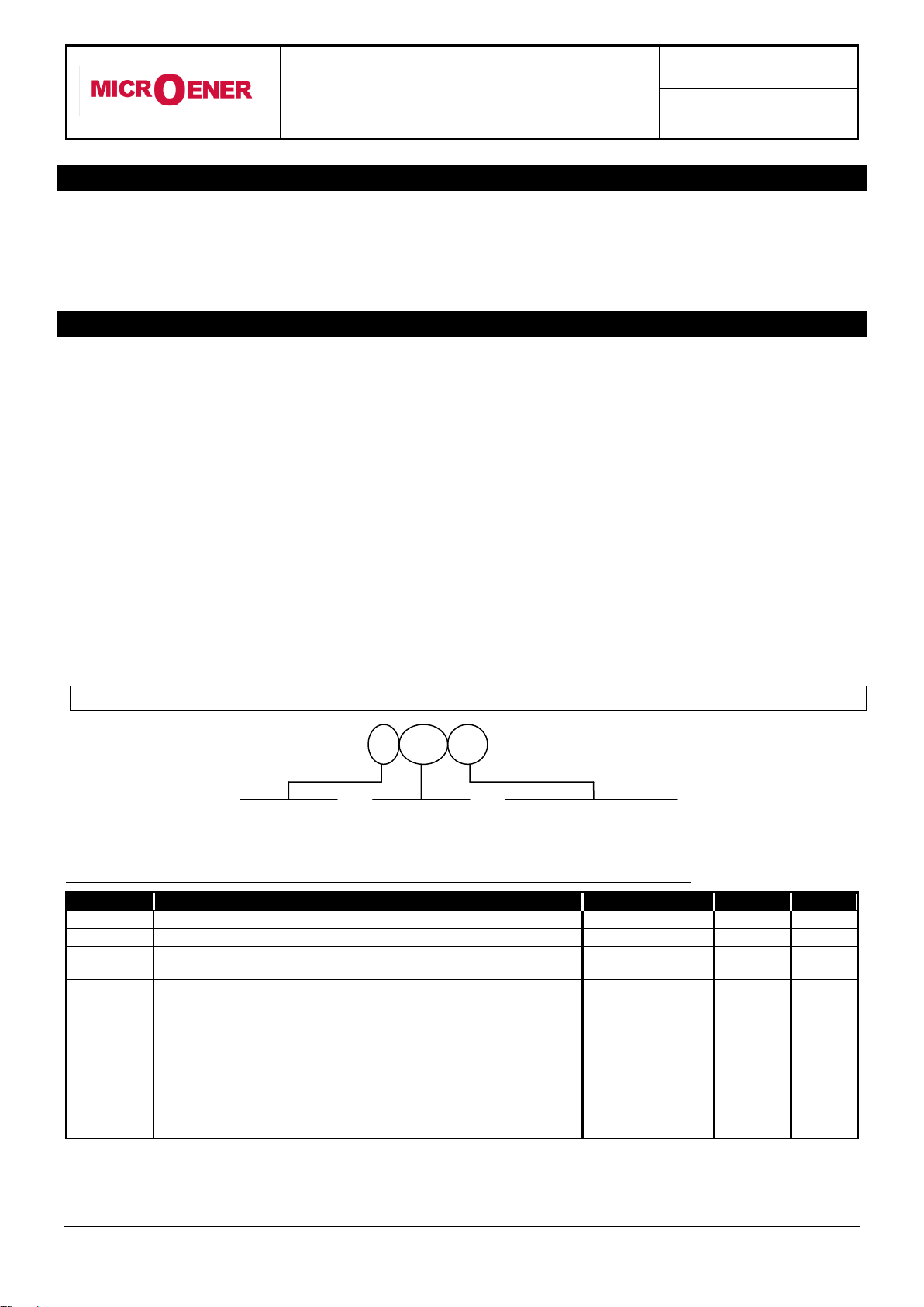
MICROPROCESSOR OVERCURRENT
AND EARTH FAULT PROTECTION RELAY
TYPE
IM30-SA
OPERATION MANUAL
MULTIFUNCTION
3ph O/C + E/F
+ Sensitive E/F
+ Neg. Seq. O/C
RELAY TYPE
IM30-SA
MODE
SELECT
+
-
I>
I>>
Io>
Io>>
PROG/
I.R.F.
S.E.F.
I2>
BLOCK ACTIVE
BRKR FAIL.
MICROELETTRICA SCIENTIFICA
MILANO ITALY
ENTER/RESET
PROG.

IM30-SA
Doc. N° MO-0089-ING
Rev. 1FW: 1.01
Pag. 2 of 25
Copyright 2010 - Microener
INDEX
1 General utilization and commissioning directions________________________________________________3
1.1 Storage and transportation________________________________________________________________ 3
1.2 Installation_____________________________________________________________________________3
1.3 Electrical connection_____________________________________________________________________ 3
1.4 Measuring inputs and power supply_________________________________________________________ 3
1.5 Outputs loading_________________________________________________________________________3
1.6 Protection earthing______________________________________________________________________ 3
1.7 Setting and calibration___________________________________________________________________ 3
1.8 Safety protection________________________________________________________________________ 3
1.9 Handling______________________________________________________________________________ 3
1.10 Maintenance___________________________________________________________________________ 4
1.11 Fault detection and repair_________________________________________________________________ 4
2 General characteristics and operation__________________________________________________________4
2.1 Power supply________________________________________________________________________4
2.2 Algorithm of the time current curves______________________________________________________ 5
3 Controls and measurements__________________________________________________________________6
4 Signalization_______________________________________________________________________________7
5 Output relays______________________________________________________________________________ 8
6 Serial communication_______________________________________________________________________ 8
7 Digital inputs______________________________________________________________________________ 9
8 Test______________________________________________________________________________________ 9
9 Keyboard and display operation_______________________________________________________________10
10 Reading of measurements and recorded parameters_____________________________________________ 11
10.1 ACT. MEAS (Actual measure) _________________________________________________________ 11
10.2 MAX VAL (Max values) _____________________________________________________________ 11
10.3 LASTTRIP (Last trip) _______________________________________________________________ 12
10.4 TRIP NUM (Trip number) ____________________________________________________________ 12
11 Reading of programmed settings and relay’s configuration________________________________________ 13
12 Programming______________________________________________________________________________ 13
12.1 Programming of functions settings______________________________________________________ 13
12.2 Programming the configuration of output relay_____________________________________________15
13 Manual and automatic test operation
13.1 Mode “ W/O TRIP ”__________________________________________________________________ 13
13.2 Mode “ WithTRIP “__________________________________________________________________ 15
14 Maintenance_______________________________________________________________________________ 16
15 Power frequency insulation test_______________________________________________________________16
16 Electrical characteristics_____________________________________________________________________17
17 Connection diagram Standard Output___________________________________________________________ 18
17.1 Double Output_____________________________________________________________________ 18
18 Wiring the serial communication bus__________________________________________________________ 19
19 Change phase rated input 1A or 5A____________________________________________________________ 19
20 Time current curves IEC_____________________________________________________________________ 20
21 Time current curves IEEE____________________________________________________________________ 21
22 Direction for pcb’s draw-out and plug-in________________________________________________________22
22.1 Draw-Out_________________________________________________________________________ 22
22.2 Plug-In___________________________________________________________________________ 22
23 Overall dimensions_________________________________________________________________________ 23
24 Keyboard operational diagram________________________________________________________________ 24
25 Setting’s form______________________________________________________________________________25

IM30-SA
Doc. N° MO-0089-ING
Rev. 1FW: 1.01
Pag. 3 of 25
Copyright 2010 - Microener
1. General utilization and commissioning directions
Always make reference to the specific description of the product and to the Manufacturer's instruction.
Carefully observe the following warnings.
1.1 - STORAGE AND TRANSPORTATION
must comply with the environmental conditions stated on the product's instruction or by the applicable
IEC standards.
1.2 - INSTALLATION
must be properly made and in compliance with the operational ambient conditions stated by the
Manufacturer.
1.3 - ELECTRICAL CONNECTION
must be made strictly according to the wiring diagram supplied with the Product, to its electrical
characteristics and in compliance with the applicable standards particularly with reference to human
safety.
1.4 - MEASURING INPUTS AND POWER SUPPLY
carefully check that the value of input quantities and power supply voltage are proper and within the
permissible variation limits.
1.5 - OUTPUTS LOADING,
must be compatible with their declared performance.
1.6 - PROTECTION EARTHING
When earthing is required, carefully check its efficiency.
1.7 - SETTING AND CALIBRATION
Carefully check the proper setting of the different functions according to the configuration of the
protected system, the safety regulations and the co-ordination with other equipment.
1.8 - SAFETY PROTECTION
Carefully check that all safety means are correctly mounted, apply proper seals where required and
periodically check their integrity.
1.9 - HANDLING
Notwithstanding the highest practicable protection means used in designing M.S. electronic circuits,
the electronic components and semiconductor devices mounted on the modules can be seriously
damaged by electrostatic voltage discharge which can be experienced when handling the modules.
The damage caused by electrostatic discharge may not be immediately apparent but the design
reliability and the long life of the product will have been reduced. The electronic circuits produced by
M.S. are completely safe from electrostatic discharge (8 KV IEC 255.22.2) when housed in their case;
withdrawing the modules without proper cautions expose them to the risk of damage.

IM30-SA
Doc. N° MO-0089-ING
Rev. 1FW: 1.01
Pag. 4 of 25
Copyright 2010 - Microener
a. Before removing a module, ensure that you are at the same electrostatic potential
as the equipment by touching the case.
b. Handle the module by its front-plate, frame, or edges of the printed circuit board.
Avoid touching the electronic components, printed circuit tracks or connectors.
c. Do not pass the module to any person without first ensuring that you are both at
the same electrostatic potential. Shaking hands achieves equipotential.
d. Place the module on an antistatic surface, or on a conducting surface which is at
the same potential as yourself.
e. Store or transport the module in a conductive bag.
More information on safe working procedures for all electronic equipment can be found
in BS5783 and IEC 147-OF.
1.10 - MAINTENANCE
Make reference to the instruction manual of the Manufacturer ;maintenance must be carried-
out by specially trained people and in strict conformity with the safety regulations.
1.11 FAULT DETECTION AND REPAIR
Internal calibrations and components should not be alterated or replaced.
For repair please ask the Manufacturer or its authorised Dealers.
Misapplication of the above warnings and instruction relieves the Manufacturer of any liability.
2. GENERAL
Input currents are supplied to 4 current transformers: - three measuring phase current - one
measuring the earth fault zero-sequence current.
Phase current input can be 1 or 5A
For zero-sequence current, taps for 1A and 5A input are provided on relay’s terminal board
dimension drawings.
Make electric connection in conformity with the diagram reported on relay's enclosure.
Check that input currents are same as reported on the diagram and on the test certificate.
The auxiliary power is supplied by a built-in interchangeable module fully isolated an self protected
2.1 - POWER SUPPLY
The relay can be fitted with two different types of power supply module :
24V(-20%) / 110V(+15%) a.c. 80V(-20%) / 220V(+15%) a.c.
a) - b) -
24V(-20%) / 125V(+20%) d.c. 90V(-20%) / 250V(+20%) d.c.
Before energising the unit check that supply voltage is within the allowed limits.

IM30-SA
Doc. N° MO-0089-ING
Rev. 1FW: 1.01
Pag. 5 of 25
Copyright 2010 - Microener
rs
atTKB
1
Is
I
A
t(I)
2.2 - ALGORITHM OF THE TIME CURRENT CURVES
The Time Current Curves are generally calculated with the following equation :
where :
t(I) = Actual trip time delay when the input current equals I
Is = Set minimum pick-up level
K=
Ts= Set time delay : t(I) = Tswhen
tr = Operation time of the output relay on pick-up.
The constants A, B, K and ahave different values for the different Time Current Curves.
Curve Name
Curve Identifier
A
B
a
K
IEC A Inverse
A
0.14
0
0.02
0.3366
IEC B Very Inverse
B
13.5
0
1
0.6667
IEC C Extr. Inverse
C
80
0
2
1.2375
IEEE Moderate Inverse
MI
0.0104
0.0226
0.02
4.1106
IEEE Short Inverse
SI
0.00342
0.00262
0.02
13.3001
IEEE Very Inverse
VI
3.88
0.0963
2
7.3805
IEEE Inverse
I
5.95
0.18
2
4.1649
IEEE Extremely Inverse
EI
5.67
0.0352
2
10.814
Independent Definite time
D
t = Ts
Curves are user selectable for the following relay’s functions
1F51 (FI>) = Low-set phase overcurrent
1F51N (FO>) = Low-set Earth Fault current
F46 (FI2>) = Negative Sequence overcurrent
For functions
2F51 (I>>, tI>>) = High-set phase overcurrent
2F51N (O>>, tO>>) = High -set Earth Fault current
the operation is Independent Definite time only
1
aB
110A
10
II
s

IM30-SA
Doc. N° MO-0089-ING
Rev. 1FW: 1.01
Pag. 6 of 25
Copyright 2010 - Microener
3. CONTROLS AND MEASUREMENTS
Five key buttons allow for local management of all relay's functions.
A 8-digit high brightness alphanumerical display shows the relevant readings (xxxxxxx)
(see synoptic table fig.1)
FIG.1
MEASURES
MAX VAL.
LASTTRIP
TRIP NUM
ACT MEAS
Actual measuremant values
Max. values measured
Values measured at last tripping
N° of tripping for each function
Measurements
display
SET DISP
SETTINGS
FRELAY
Display of setting
Display of configuration of output relay
Setting Program
display
PROGR
SETTINGS
FRELAY
Setting of parameters
Configuration of output relays
Set Programming
PROG
TEST PRG
W/O TRIP
WithTRIP
Functional Test
Test with operation of signals and output relays
Test with operation of signals only
Test activation
by the key ENTER
Paramater scanning
by the key
SELECT
Parameter modification
by the key “+” “-”
Set validation
by the key ENTER
Scanning of
the menus by
the key
“+” “-”
MODE
SELECT
ENTER
+ -
(*) Enabled only if input current is zero
(*)
(*)
ENTER/RESET
MODE
SELECT
+
-
PROG.
The SELECT button chooses
which category of values within the
chosen mode to display
Pressing this button progressively
selects between
Measurements Display,
Setting Display, Programming,
and Test modes
When in Program mode, this
button stores the newly selected
value. If not in Program mode and
the relay has tripped, this button
resets the relay and all output
contacts. If not tripped, this button
restores the default display.
The + and - buttons are used to
select the actual measurement or
display desired when in
Measurements Display or Settings
Display modes. When in Program
mode, these buttons increase or
decrease the value of the
displayed setting.
When in Program mode, and when
all input currents are zero,
pressing this recessed button
places the relay into active
programming mode, allowing any
or all of the relay’s settings to be
altered.
IM30-SA
Doc. N° MO-0089-ING
Rev. 1FW: 1.01
Pag. 7 of 25
Copyright 2010 - Microener
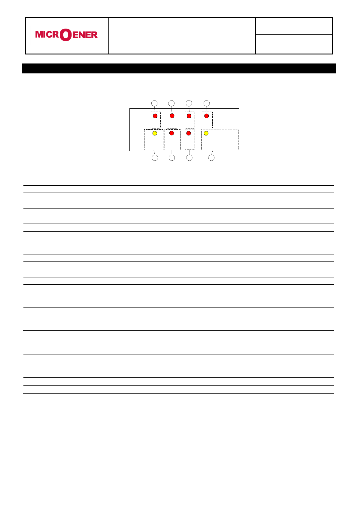
4. SIGNALIZATIONS
Eight signal leds (normally off) are provided:
a)
Red LED
I>
Flashing when measured current overcomes the set trip level [I>].
Illuminated on trip after expiry of the set trip time delay [tI>].
b)
Red LED
I>>
Same as above related to [I>>], [tI>>].
c)
Red LED
Io>
Same as above related to [O>], [tO>].
d)
Red LED
Io>>
Same, as above related to [O>>], [tO>>].
e)
Yellow LED
PROGRAM/
BLOCK FAIL
Flashing during the programming of the parameters or in case
Illuminated on Internal Relay Fault.
f)
Red LED
S.E.F.
Flashing when measured current overcomes the set trip level [I>].
Illuminated on trip after expiry of the set trip time delay [tI>].
g)
Red LED
I2>
Flashing when measured current overcomes the set trip level [I>].
Illuminated on trip after expiry of the set trip time delay [tI>].
h)
Yellow LED
BLOCK ACTIVE
BRKR FAIL
Flashing when a blocking signal is present at the relevant input
terminals.
Lit-on when the BREAKER FAILURE function is activated.
The reset of the leds takes place as follows:
Leds
a,b,c,d,g
From flashing to off, automatically when the lit-on cause disappears.
From ON to OFF, by "ENTER/RESET" push button only if the
tripping cause has disappeared.
Leds
e,f,h
From ON to OFF, automatically when the lit-on cause disappears.
In case of auxiliary power supply failure the status of the leds is recorded and reproduced when power
supply is restored.
I>
I>>
Io>
Io>>
BLOCK ACTIVE
BRKR FAIL
PROG/
S.E.F.
I2>
I.R.F.
a
b
c
d
e
f
g
h

IM30-SA
Doc. N° MO-0089-ING
Rev. 1FW: 1.01
Pag. 8 of 25
Copyright 2010 - Microener
5. OUTPUT RELAYS
Five output relays are available (R1, R2, R3, R4, R5)
The relays R1,R2,R3,R4 are normally deenergized (energised on trip): these output relays are user
programmable and any of them can be associated to one of the IM30-SA's functions.
One relay eventually associated to the instantaneous element of one of the functions, after pick-up
normally drops-out as soon as the tripping cause disappears (current below the set trip level).
If the current remains above the trip level longer than the time delay programmed for the relevant
function, the drop-out of the instantaneous relay is anyhow forced after an adjustable waiting time
[tBO].(Diasactivation of the blocking output eventually used to block a relay upstream in the
distribution system).
Moreover any of the relays R1,R2,R3,R4, can be programmed to be energised at the end of the
delay tBF(Breaker Failure function)
Reset of the output relays associated to any time delayed function can be programmed to take
place “Automatically” (tFRes= A) as soon as the tripping cause has disappeared, or “Manually”
(tFRes= M) only by operating the ENTER/RESET key on relay’s front or via the serial bus.
It has to be remarked that the programming structure does not allow to associate the same relay at
the same time to instantaneous and delayed elements. Therefore any relay already associated to
any time delayed element cannot be associated to any instantaneous element and viceversa.
The relay R5, normally energised, is not programmable and it is deenergized on:
internal fault
power supply failure
during the programming
6. SERIAL COMMUNICATION
The relays fitted with the serial communication option can be connected via a cable bus a fiber optic bus
for interfacing with a Personal Computer (type IBM or compatible).
All the functionalities that can be operated locally (for example reading of input measurement and
changing of relay’s settings) are also possible via the serial communication interface.
Furthermore the serial port allows the user to read event recording and stored data.
The unit has a RS232 / RS485 interface and can be connected either directly to a P.C. via a dedicated
cable or to a RS485 serial bus, allowing having many relays to exchange data with a single master P.C.
using the same physical serial line. A RS485/232 converter is available on request.
The communication protocol is MODBUS RTU (only functions 3, 4 and 16 are implemented).
Each relay is identified by its programmable address code (NodeAd) and can be called from the P.C.
A dedicated communication software (MSCOM) for Windows 95/98/NT4 SP3 (or later) is available.
Please refer to the MSCOM instruction manual for more information Microelettrica Scientifica.

IM30-SA
Doc. N° MO-0089-ING
Rev. 1FW: 1.01
Pag. 9 of 25
Copyright 2010 - Microener
7. DIGITAL INPUTS
Three digital inputs are provided: they are active when the relevant terminals are shorted
Bf
terminals
1 –2
:
it blocks the operation of the time delayed elements relevant to phase fault
detection.
Bo
terminals
1 –3
:
it blocks the operation of the time delayed elements relevant to earth fault and
Sensitive E/F detection.
RR
terminals
1 –14
:
Remote Reset
When a function is blocked the pick-up of its time delayed output is inhibited. Programming allows to
have the inhibition either permanent as long as the blocking input is active (tBf=OFF; tBo=OFF) or
automatically removed after the expiry of the set trip time delay of the function involved plus an
additional time 2tBF (tBf=2tBO; tBo=2tBO). By proper interconnection of the blocking inputs and outputs
of different relays it is possible to configurate very efficient arrangements of logic fault discrimination as
well as to feature a safe and quick breaker back-up protection.
8. TEST
Besides the normal "WATCHDOG" and "POWERFAIL" functions, a comprehensive program of self-test
and self-diagnostic provides:
Diagnostic and functional test, with checking of program routines and memory's content, run every
time the aux. power is switched-on: the display shows the type of relay and its version number.
Dynamic functional test run during normal operation every 15 min. (relay's operation is suspended
for less than 4 ms). If any internal fault is detected, the display shows a fault message, the Led
"PROG/IRF" illuminates and the relay R5 is deenergized.
Complete test activated by the keyboard or via the communication bus either with or without tripping
of the output relays.
IM30-SA
Doc. N° MO-0089-ING
Rev. 1FW: 1.01
Pag. 10 of 25
Copyright 2010 - Microener
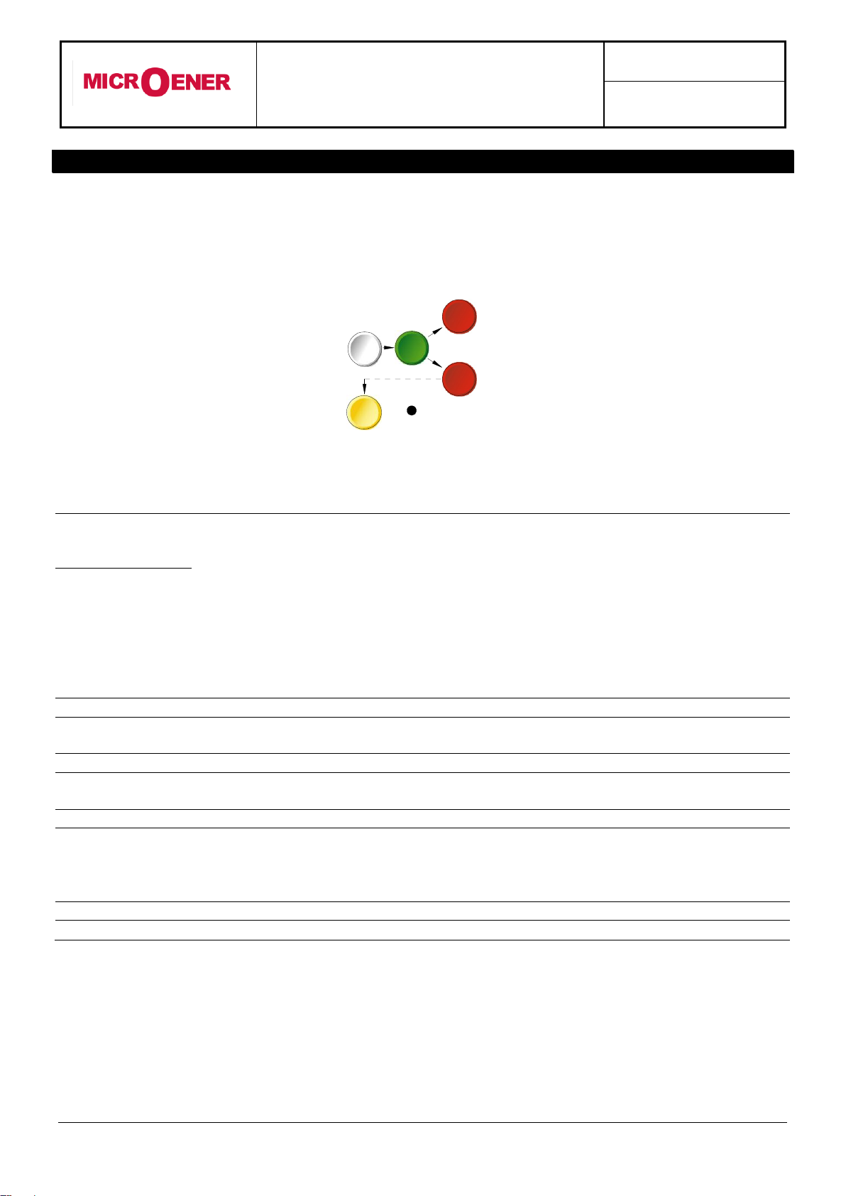
9. KEYBOARD AND DISPLAY OPERATION
All controls can be operated from relay's front or via serial communication bus.
The keyboard includes five hand operable buttons (MODE) - (SELECT) - (+) - (-) - (ENTER/RESET)
plus one indirect operable key (PROG) (see synoptic table a fig.1):
a)
-
White key
MODE
:
when operated it enters one of the following operation modes
indicated on the display :
MEASURES
=
Reading of all the parameters measured and of those recorded
in the memory
SET DISP
=
Reading of the settings and of the configuration of the output
relays as programmed.
PROG
=
Access to the programming of the settings and of relay
configuration.
TEST PROG
=
Access to the manual test routines.
b)
-
Green key
SELECT
:
When operated it selects one of the menus available in the
actual operation MODE
c)
-
Red key
“+”AND “-“
:
When operated they allow to scroll the different information
available in the menu entered by the key SELECT
d)
-
Yellow key
ENTER/RESET
:
It allows the validation of the programmed settings
- the actuation of test programs
- the forcing of the default display indication
- the reset of signal Leds.
e)
-
Indirect key
:
Enables access to the programming.
ENTER/RESET
MODE
SELECT
+
-
PROG.
IM30-SA
Doc. N° MO-0089-ING
Rev. 1FW: 1.01
Pag. 11 of 25
Copyright 2010 - Microener
10. READING OF MEASUREMENTS AND RECORDED PARAMETERS
Enter the MODE "MEASURE", SELECT the menus "ACT.MEAS"-"MAX VAL"-"LASTTRIP"- "TRIP
NUM", scroll available information by key "+" or "-" .
10.1 - ACT.MEAS
Actual values as measured during the normal operation. The values displayed are continuously
refreshed.
The display scrolls the different measurements every 2 seconds.
To stop on any of the measurements displayed just press the “Enter/Reset” push button.
Display
Description
I/Inxxx%
Highest among the 3 phase-currents displayed as % of the rated current of phase C.Ts
(0-999%)
IAxxxxxA
True R.M.S. value of the current of phase A displayed as primary Amps.(0 - 99999)
IBxxxxxA
As above, phase B.
ICxxxxxA
As above, phase C.
IoxxxxxA
As above, earth fault current.
I2xxxxxIn
Negative Sequence component of the 3-phase current system displayed as p.u. of C.Ts
rated current.
10.2 - MAX VAL
Maximum demand values recorded starting from 100ms after closing of main Circuit Breaker plus
highest inrush values recorded within the first 100ms from Breaker closing, (updated any time the
breaker closes).
Display
Description
IAxxxxIn
Max. value of phase A current after the first 100ms, displayed as p.u. of C.Ts rated
current.
IBxxxxIn
As above, phase B.
ICxxxxIn
As above, phase C.
IoxxxxOn
As above, earth fault current.
I2xxxxxIn
As above, negative sequence current component
SAxxxxIn
Max. current of phase A during the first 100ms.
SBxxxxIn
As above, phase B.
SCxxxxIn
As above, phase C.
SoxxxxOn
As above, earth fault current.
IM30-SA
Doc. N° MO-0089-ING
Rev. 1FW: 1.01
Pag. 12 of 25
Copyright 2010 - Microener
10.3 - LASTTRIP
Display of the function which caused the tripping of the relay plus values of the parameters at the
moment of tripping. The last five events are recorded
The memory buffer is refreshed at each new relay tripping with a decreasing numbering (FIFO logic).
Display
Description
LastTr-x
Indication of the recorded event (x= 0 to 4)
Example: Last event (LastTr -0) - Last but one event (LastTr-1) - etc...
F:xxxxxx
Function which produced the event being displayed and faulty phase in case of phase
current element’s trip I> ph A,B,C; I>> ph A,B,C; O>; O>>.
IAxxxxIn
Current of phase A. (value recorded at the moment of tipping)
IBxxxxIn
Current of phase B. (as above)
ICxxxxIn
Current of phase C. (as above)
IoxxxxOn
Earth fault current. (as above)
I2xxxxxIn
Negative Sequence component of current.
10.4 - TRIP NUM
Counters of the number of operations for each of the relay functions.
The memory is non-volatile and can be cancelled only with a secret procedure.
Display
Description
I> xxxx
Trip number of Low set overcurrent time delayed element [tI>].
I>>xxxx
Trip number of High set overcurrent time delayed element [tI>>].
Io> xxxx
Trip number of Low set earth fault time delayed element [tO>].
Io>>xxxx
Trip number of High set earth fault time delayed element [tO>>].
So>xxxxx
Trip number of Sensitive earth fault time delayed element [tSo>].
I2xxxxx
Trip number of Negative Sequence O/C time delayed element [tI2>].
IM30-SA
Doc. N° MO-0089-ING
Rev. 1FW: 1.01
Pag. 13 of 25
Copyright 2010 - Microener
11. READING OF PROGRAMMED SETTINGS AND RELAY'S CONFIGURATION
Enter the mode "SET DISP", select the menu "SETTINGS" or "F
RELAY", scroll information
available in the menu by keys "+" or "-".
SETTINGS= values of relay's operation parameters as programmed
F
RELAY= output relays associated to the different functions as programmed.
12. PROGRAMMING
The relay is supplied with the standard default programming used for factory test. [ Values here below
reported ( ----- ) ].
All parameters can be modified as needed in the mode PROG and displayed in the mode SET DISP
Local Programming by the front face key board is enabled only if no input current is detected
(main switch open). Programming via the serial port is always enabled but a password is
required to access the programming mode. The default password is the null string; in the
standard application program for communication “MS-COM” it is also provided an emergency
which can be disclosed on request only.
As soon as programming is enabled, the Led PRG/IRF flashes and the reclosing lock-out relay R5 is
deenergized.
Enter MODE "PROG" and SELECT either "SETTINGS" for programming of parameters or
"F
RELAY" for programming of output relays configuration; enable programming by the indirect
operation key PROG.
The key SELECT now scrolls the available parameters. By the key (+) , (-) the displayed values can be
modified; to speed up parameter's variation press the key SELECT while "+" or "-" are pressed.
Press key "ENTER/RESET" to validate the set values.
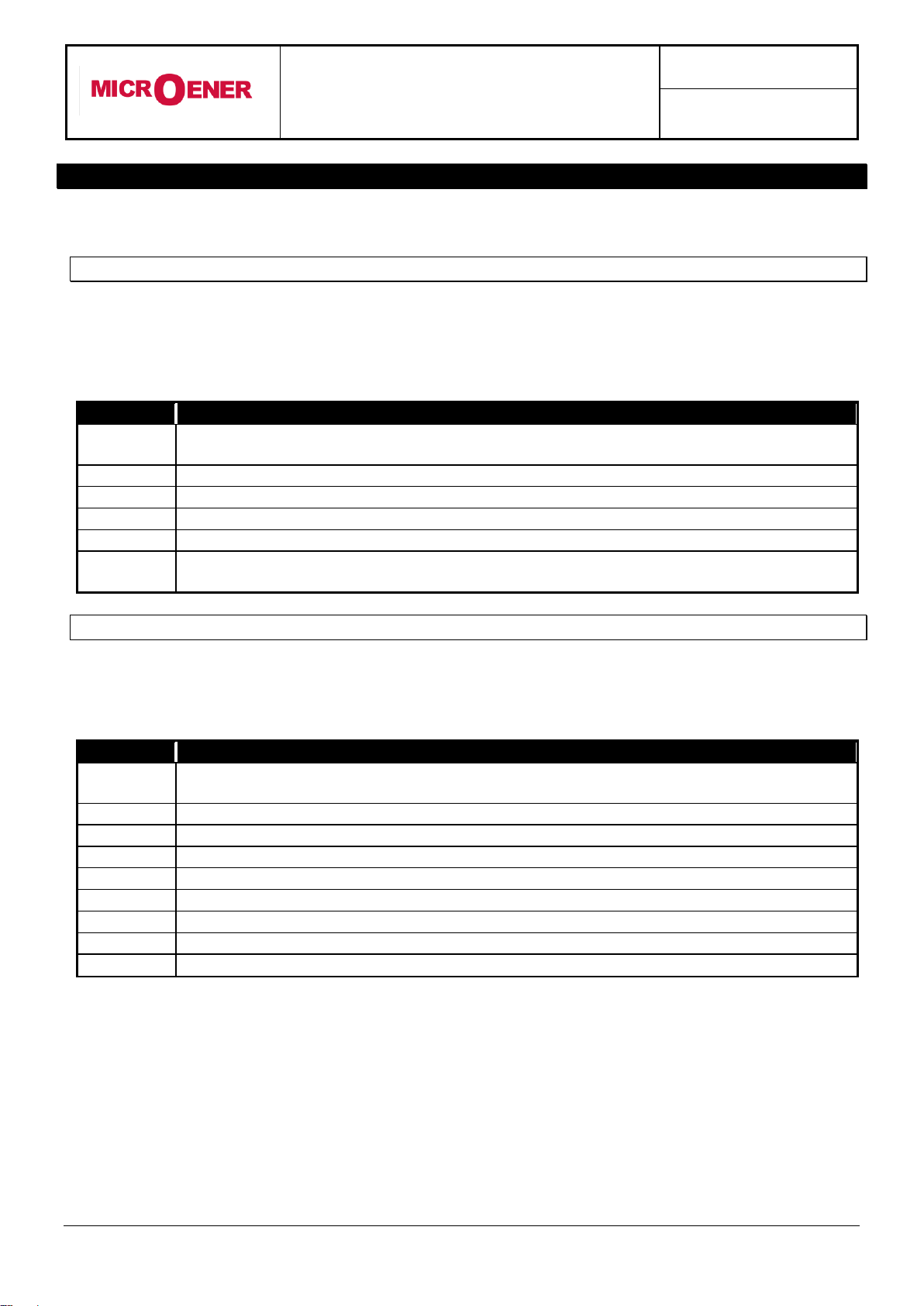
12.1 - PROGRAMMING OF FUNCTIONS SETTINGS
Mode PROG menu SETTINGS. (Production standard settings here under shown).
Display
Description
Setting Range
Step
Unit
Fn 50 Hz
Mains frequency
50 - 60
10
Hz
In 500Ap
Rated primary current of the phase C.Ts.
1 - 9999
1
A
On 500Ap
Rated primary current of the C.Ts. or of the tore C.T. supplying the
zero sequence current
1 - 9999
1
A
F(I>) D
Operation characteristic of the low-set overcurrent element:
(D) = Independent definite time
(A) = IEC Inverse Curve type A
(B) = IEC Very Inverse Curve type B
(C) = IEC Extremely Inverse Curve type C
(MI) = IEEE Moderate Inverse Curve
(SI) = IEEE Short Inverse Curve
(VI) = IEEE Very Inverse Curve
(I) = IEEE Inverse Curve
(EI) = IEEE Extremely Inverse Curve
D
A
B
C
MI
SI
VI
I
EI
D
A
B
C
MI
SI
VI
I
EI
-
In 500 Ap
Ap is the unit of measure,
Amps primary.
500 is the
setting default
In is the name
of the variable
IM30-SA
Doc. N° MO-0089-ING
Rev. 1FW: 1.01
Pag. 14 of 25
Copyright 2010 - Microener
Display
Description
Setting Range
Step
Unit
I> 0.5In
Trip level of low-set overcurrent element (p.u. of the rated current
of the phase C.Ts.)
0.16 - 4 - Dis
0.01
In
tI> 0.05s
Trip time delay of the low-set overcurrent element
In the inverse time operation [tI>] is the trip time delay
at I = 10x[I>].
0.01 - 30
0.01
s
2I>> ON
Automatic Cold Load pick-up
ON - OFF
ON-OFF
-
I>> 0.5In
Trip level of high-set overcurrent element (p.u. of the rated current
of the phase C.Ts.):
0.1 - 40 - Dis
0.1
In
tI>> 0.05s
Trip time delay of the high-set overcurrent element
0.01 - 3
0.01
s
F(O>) D
Operation characteristic of the low-set earth fault element:
(D) = Independent definite time
(A) = IEC Inverse Time Curve type A
(B) = IEC Very Inverse Time Curve type B
(C) = IEC Extremely Inverse Time Curve type C
(MI) = IEEE Moderate Inverse Curve
(SI) = IEEE Short Inverse Curve
(VI) = IEEE Very Inverse Curve
(I) = IEEE Inverse Curve
(EI) = IEEE Extremely Inverse Curve
D
A
B
C
MI
SI
VI
I
EI
D
A
B
C
MI
SI
VI
I
EI
-
O> 0.02On
Trip level of low-set earth fault element (p.u. of the rated current of
the C.Ts. for zero sequence detection)
0.02 - 0.4 - Dis
0.01
On
tO> 0.05s
Trip time delay of low-set earth fault element. In the inverse time
operation [tO>] is the trip time delay at I = 10x[O>].
0.01 - 30
0.01
s
O>>0.02On
Trip level of high-set earth fault element
(p.u. of the rated current of the C.Ts. for zero sequence detection)
0.02 - 4 - Dis
0.01
On
tO>> 0.05s
Trip time delay of the high-set earth fault element
0.01 - 3
0.01
s
So 0.05On
Trip level of Sensitive E/F element (p.u. of the rated current of the
C.Ts. for zero sequence detection)
0.01 - 0.05 - Dis
0.001
On
tSo 0.05s
Trip time delay Sensitive E/F element. In the inverse time operation
[tO>] is the trip time delay at I = 10x[O>].
0.01 - 30
0.1
s
F(I2) D
Operation characteristic of the Negative Sequence element:
(D) = Independent definite time
(A) = IEC Inverse Curve type A
(B) = IEC Very Inverse Curve type B
(C) = IEC Extremely Inverse Curve type C
(MI) = IEEE Moderate Inverse Curve
(SI) = IEEE Short Inverse Curve
(VI) = IEEE Very Inverse Curve
(I) = IEEE Inverse Curve
(EI) = IEEE Extremely Inverse Curve
D
A
B
C
MI
SI
VI
I
EI
D
A
B
C
MI
SI
VI
I
EI
-
I21.0In
Trip level of the negative sequence overcurrent element
(p.u. of the rated current of phase C.Ts)
0.05 –2.5 - Dis
0.01
In
tI2>0.05s
Trip time delay of the negative sequence element. In the inverse
time operation [tI2>] is the trip time delay at I2=10x[I2>]
0.05 –30
0.01
s
tBO0.05s
Max. reset time delay of the instantaneous elements after tripping
of the time delayed elements and time delay for activation of the
output relay associated to the Breaker Failure function
0.05 - 0.25
0.01
s
NodAd 1
Identification number for connection on serial communication bus
1 - 250
1
-
The setting Dis indicates that the function is disactivated.

IM30-SA
Doc. N° MO-0089-ING
Rev. 1FW: 1.01
Pag. 15 of 25
Copyright 2010 - Microener
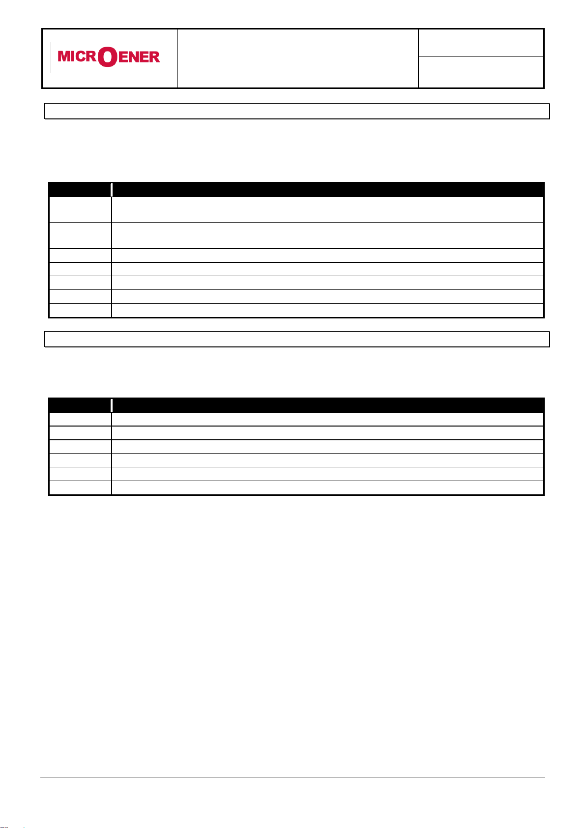
12.2 - PROGRAMMING THE CONFIGURATION OF OUTPUT RELAYS
Mode PROG menu FRELAY (Production standard settings here under shown).
The key "+" operates as cursor; it moves through the digits corresponding to the four programmable
relays in the sequence 1,2,3,4,(1= relay R1, etc.) and makes start flashing the information actually
present in the digit. The information present in the digit can be either the number of the relay (if this was
already associated to the function actually on programming) or a dot (-) if the relay was not yet
addressed.
The key "-" changes the existing status from the dot to the relay number or viceversa.
Display
Description
I> --3-
Instantaneous element of low-set overcurrent
(only one or more, whatever combination)
operates relays R1,R2,R3,R4.
tI> 1---
As above, time delayed element.
operates relay R1,R2,R3,R4.
I>> --3-
Instantaneous element of high-set overcurrent
operates relay R1,R2,R3,R4.
tI>> 1---
As above, time delayed element.
operates relay R1,R2,R3,R4.
O> ---4
Instantaneous element of low-set earth fault element
operates relay R1,R2,R3,R4.
tO> -2--
As above, time delayed element.
operates relay R1,R2,R3,R4.
O>> ---4
Instantaneous element of high-set earth fault element
operates relay R1,R2,R3,R4.
tO>> -2--
As above, time delayed element.
operates relay R1,R2,R3,R4.
So> ---4
Instantaneous element of Sensitive earth fault element
operates relay R1,R2,R3,R4.
tSo> -2--
As above, time delayed element.
operates relay R1,R2,R3,R4.
I2>--3-
Instantaneous element of Negative Sequence O/C
element
operates relay R1,R2,R3,R4.
tI2>1---
As above, time delayed element.
operates relay R1,R2,R3,R4.
tFRes: A
The reset after tripping of the relays associated to the time delayed elements can take
place: (A) automatically when current drops below the trip level.
(M) manually by the operation of the "ENTER/RESET" key.
Bf -Ii
The input (Bf) can block the operation of one or more of the time delayed O/C element,
N= Negative Sequence O/C (I2>), i= low-set O/C (I>), I= High-set O/C (I>>)
Bo -Oo
The input (Bo) can block the operation of one or more of the time delayed E/F element,
S= Sensitive E/F (So), o= low-set E/F (O>), O= High-set E/F (O>>)
tBf 2tB0
The blocking of the phase fault elements can be programmed so that it lasts as long as
the blocking input signal is present (tBf Dis) or so that, even with the blocking input still
present, it only lasts for the set trip time delay of the function plus an additional time 2xtBO
(tBf 2xtBO).
tBo 2tB0
As above, for the earth fault elements (tBo Dis) or (tBo 2tBO).
I> -2 - 4
This dash means
that output relay
number 1 is not
assigned to this
element
This is the name of
protective element
The number 2
means that
output relay 2 will
operate when
this element trips
This dash means
that output relay
number 3 is not
assigned to this
element
The number 4 means
that output relay 4 will
operate when this
element trips

IM30-SA
Doc. N° MO-0089-ING
Rev. 1FW: 1.01
Pag. 16 of 25
Copyright 2010 - Microener
13. MANUAL AND AUTOMATIC TEST OPERATION
13.1 - Mode "TESTPROG" subprogram "W/O TRIP"
Operation of the yellow key activates a complete test of the electronics and the process routines.
All the leds are lit-on and the display shows (TEST RUN). If the test routine is successfully
completed the display switches-over to the default reading (I/Inxxx%)
If an internal fault is detected, the display shows the fault identification code and the relay R5 is
deenergized. This test can be carried-out even during the operation of the relay without affecting the
relay tripping in case a fault takes place during the test itself.
13.2 - Mode "TESTPROG" subprogram "WithTRIP"
Access to this program is enabled only if the current detected is zero (breaker open).
Pressing the yellow key the display shows "TEST RUN?". A second operation of the yellow key
starts a complete test which also includes the activation of all the output relays.
The display shows (TEST RUN) with the same procedure as for the test with W/O TRIP.
Every 15 min during the normal operation the relay automatically initiates an auto test procedure
(duration 10ms). If any internal fault is detected during the auto test, the relay R5 is deenergized,
the relevant led is activated and the fault code is displayed.
WARNING
Running the WithTRIP test will operate all of the output relays. Care must be taken to ensure that no
unexpected or harmful equipment operations will occur as a result of running this test.
It is generally recommended that this test be run only in a bench test environment or after all
dangerous output connections are removed.
14. MAINTENANCE
No maintenance is required. Periodically a functional check-out can be made with the test procedures
described under MANUAL TEST chapter. In case of malfunctioning please contact
Microelettrica Scientifica Service or the local Authorised Dealer mentioning the relay's Serial No reported
in the label on relays enclosure.
WARNING
In case of Internal Relay Fault detection, proceed as here-below indicated :
If the error message displayed is one of the following “DSP Err”, “ALU Err” ,”KBD Err” ,”ADC Err”,
switch off power supply and switch-on again. If the message does not disappear send the relay to
Microelettrica Scientifica (or its local dealer) for repair.
If the error message displayed is “E2P Err”, try to program any parameter and then run “W/OTRIP”.
If message disappear please check all the parameters.
If message remains send the relay to Microelettrica Scientifica (or its local dealer) for repair.
15. POWER FREQUENCY INSULATION TEST
Every relay individually undergoes a factory insulation test according to IEC255-5 standard at
2 kV, 50 Hz 1min. Insulation test should not be repeated as it unusefully stresses the dielectrics.
When doing the insulation test, the terminals relevant to serial output must always be short circuited to
ground. When relays are mounted in switchboards or relay boards that have to undergo the insulation
tests, the relay modules must be drawn-out of their enclosures and the test must only include the fixed
part of the relay with its terminals and the relevant connections.
This is extremely important as discharges eventually tacking place in other parts or components of the
board can severely damage the relays or cause damages, not immediately evident to the electronic
components.

IM30-SA
Doc. N° MO-0089-ING
Rev. 1FW: 1.01
Pag. 17 of 25
Copyright 2010 - Microener
16. ELECTRICAL CHARACTERISTICS
APPROVAL: CE –RINA
REFERENCE STANDARDS IEC 60255 - EN50263 - CE Directive - EN/IEC61000 - IEEE C37
Dielectric test voltage
IEC 60255-5
2kV, 50/60Hz, 1 min.
Impulse test voltage
IEC 60255-5 : 5kV (c.m.), 2 kV (d.m.) - 1,2/50s
5kV (c.m.), 2kV (d.m.) –1,2/50s
Insulation resistance
> 100M
Environmental Std. Ref. (IEC 68-2-1 - 68-2-2 - 68-2-33)
Operation ambient temperature
-10°C / +55°C
Storage temperature
-25°C / +70°C
Humidity
IEC68-2-3 RH 93% Without Condensing AT 40°C
CE EMC Compatibility (EN50081-2 - EN50082-2 - EN50263)
Electromagnetic emission
EN55022
industrial environment
Radiated electromagnetic field immunity test
IEC61000-4-3
level 3
80-1000MHz
10V/m
ENV50204
900MHz/200Hz
10V/m
Conducted disturbances immunity test
IEC61000-4-6
level 3
0.15-80MHz
10V
Electrostatic discharge test
IEC61000-4-2
level 4
6kV contact / 8kV air
Power frequency magnetic test
IEC61000-4-8
1000A/m
50/60Hz
Pulse magnetic field
IEC61000-4-9
1000A/m, 8/20s
Damped oscillatory magnetic field
IEC61000-4-10
100A/m, 0.1-1MHz
Electrical fast transient/burst
IEC61000-4-4
level 3
2kV, 5kHz
HF disturbance test with damped oscillatory wave (1MHz
burst test)
IEC60255-22-1
class 3
400pps, 2,5kV (m.c.), 1kV (d.m.)
Oscillatory waves (Ring waves)
IEC61000-4-12
level 4
4kV(c.m.), 2kV(d.m.)
Surge immunity test
IEC61000-4-5
level 4
2kV(c.m.), 1kV(d.m.)
Voltage interruptions
IEC60255-4-11
Resistance to vibration and shocks
IEC60255-21-1 - IEC60255-21-2 10-500Hz 1g
CHARACTERISTICS
Accuracy at reference value of influencing factors
2% Rated Input - 0,1% On
for measure
2% +/- 10ms
for times
Rated Current
In = 1 or 5A - On = 1 or 5A
Current overload
200 A for 1 sec; 10A continuos
Burden on current inputs
Phase : 0.01VA at In = 1A; 0.2VA at In = 5A
Neutral : 0.03VA at On =1A ; 0.2VA at On = 5A
Average power supply consumption
8.5 VA
Output relays
rating 5 A; Vn = 380 V
A.C. resistive switching = 1100W (380V max)
make = 30 A (peak) 0,5 sec.
break = 0.3 A, 110 Vcc,
L/R = 40 ms (100.000 op.)
Microelettrica Scientifica S.p.A. - 20089 Rozzano (MI) - Italy - Via Alberelle, 56/68
Tel. (##39) 02 575731 - Fax (##39) 02 57510940
The performances and the characteristics reported in this manual are not binding and can modified at any moment without notice

IM30-SA
Doc. N° MO-0089-ING
Rev. 1FW: 1.01
Pag. 18 of 25
Copyright 2010 - Microener
17. CONNECTION DIAGRAM STANDARD OUTPUT (SCE1575 Rev.0)
17.1 CONNECTION DIAGRAM DOUBLE OUTPUT (SCE1576 Rev.0)

IM30-SA
Doc. N° MO-0089-ING
Rev. 1FW: 1.01
Pag. 19 of 25
Copyright 2010 - Microener
18. WIRING THE SERIAL COMMUNICATION BUS (SCE1309 Rev.0)
19. CHANGE PHASE CURRENT RATED INPUT 1 OR 5A
J1
Phase A
J2
Phase B
J3
Phase C
Rated
Input
Current
Rated Input
Current
Rated Input
Current
Jumper
Connector

IM30-SA
Doc. N° MO-0089-ING
Rev. 1FW: 1.01
Pag. 20 of 25
Copyright 2010 - Microener
20. TIME CURRENT CURVES IEC (TU0353 Rev.0 1/2)
Table of contents
Other MICROENER Relay manuals

MICROENER
MICROENER IM30-GLF User manual

MICROENER
MICROENER ELR-3B User manual

MICROENER
MICROENER ELRC-1 User manual

MICROENER
MICROENER IM3G-VX User manual

MICROENER
MICROENER MM30-W User manual

MICROENER
MICROENER M-LIB3 User manual

MICROENER
MICROENER MG30 User manual

MICROENER
MICROENER MC20-X/10-4 User manual

MICROENER
MICROENER IM30-B00 User manual

MICROENER
MICROENER ULTRA Series User manual


