8
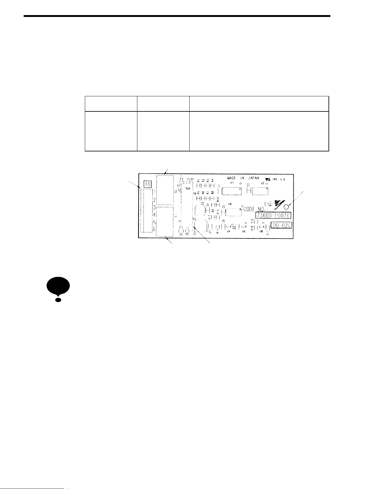
5Related constants for 2C-Relay Output Card DO-02C
Table 2Related constants for 2C-Relay Output Card DO-02C
Operator
function
display
Operator
display
Constant
No. Name Setting
range
Factory
setting
Change
during
operation
Reference
DO-02
Ch1 Select
F5-01 Channel 1 output
selection
0toFF 0 Disabled SRefer to Table 3 for the output func-
tion.
-
DO-02
Ch2 Select
F5-02 Channel 2 output
selection
0toFF 1 Disabled
S
e
er to t
e
unct
on se
ect
on o
t
e
multi-function output terminal of the
inverter for details of each function.
Table 3Multi-function Output Functions of DC-02C
Setting
value Function Setting
value Function
00 During run (ON: run command is input or during in-
verter output)
20 −
01 Zero speed 21 −
02 Frequency agree 1 22 −
03 Desired frequency agree 1 23 −
04 Frequency detection 1 24 −
05 Frequency detection 2 25 −
06 Inverter Operation ready 26 −
07 During undervoltage (UV) detection 27 −
08 During baseblock (NO contact output) 28 −
09 Frequency reference mode 29 −
0A Run command mode 2A −
0B Overtorque detection 1 (NO contact output) 2B −
0C Loss of frequency reference 2C −
0D Braking resistor fault 2D −
0E Fault (Faults other than CPF00 or CPF01) 2E −
0F −2F −
10 Alarm 30 During torque limit *2
11 Fault reset command active 31 During speed limit *1
12 Timer function output 32 −
13 Frequency agree 2 33 During zero-servo *1
14 Desired frequency agree 2 34 −
15 Frequency detection 3 35 −
16 Frequency detection 4 36 −
17 Overtorque detection 1 (NC contact output) 37 During run 2 (Other than Base block, DC injection
braking, initial excitation)
18 Overtorque detection 2 (NO contact output) 38 −
19 Overtorque detection 2 (NC contact output) 39 −
1A During reverse run 3A −
1B During baseblock (NC contact output) 3B −
1C −3C −
1D Regenerating/motoring mode (Closed during regener-
ating mode) *1
3D −
1E Restart enabled 3E −
1F Motor overload (OL1) pre-alarm 3F −
* 1. Can be used during Flux vector control mode.
* 2. Can be used during Open loop vector or Flux vector control mode.