Sterling Sterilisers Acuatic Vacuum 12 B User manual

Sterling Sterilisers
Acuatic Vacuum 12 B
User Instructions

Read these Instructions before using the Steriliser
Please take time to read these instructions before using the steriliser for the first time, then keep them in a safe
convenient place for future reference.
After Sales Service
Sterling Sterilisers staff are available to provide verbal advice and assistance by phone during normal office hours and
to answer written queries by post or email. For further information visit www.sterlingsterilisers.com
Symbol Explanation
Acuatic Vacuum steriliser
020 3289 9916
Sterling Sterilisers Ltd
Wenta Business Centre
Colne Way
Watford WD24 7ND
sales@sterlingsterilisers.com
This symbol confirms that the Acuatic Vacuum steriliser complies with Council Directive 93/42/EEC
concerning medical devices as amended by Directive 98/79/EC, Directive 2000/70/EC, Directive
2001/104/EC and Regulation (EC) No 1882/2003. 0086 indicates that the Notified Body employed to
check conformation with the above is BSI.
This symbol indicates that the number next to it is the serial number of the steriliser.
This symbol indicates that the information next to it is the date of manufacture and the name and
address of the manufacturer.
This symbol indicates that the user should read the User Instructions.
This symbol indicates that in order to comply with EU Directive 2002/96/EC for Waste Electrical and
Electronic Equipment (WEEE) the steriliser should be returned to Sterling Sterilisers or disposed of at
an appropriate facility at the end of its working life in order to enable recovery and recycling in an
environmentally sound manner.
This symbol is used to highlight the fact that there are specific warnings or precautions associated with
the steriliser that the reader should be aware of.
Copyright © 2012. Sterling Sterilisers Ltd. All trademarks or registered trademarks are the property of Sterling Sterilisers Ltd
User Instructions

Acuatic Vacuum steriliser
Introduction
Features ...................................................................1
Parts Supplied ...................................................................1
Guarantee ..................................................................1
Pressure Vessel ..................................................................1
Contents
Illustration
Illustration ...................................................................2
Cycle Charts ...................................................................2
Safety
General Safety ..................................................................3
Safety Features ..................................................................3
Ambient Conditions ..................................................................3
Processing Limitations ..................................................................3
Care and Data Logger
Daily Maintenance ..................................................................4
Daily Testing ..................................................................4
Weekly Testing .................................................................4
Servicing ..................................................................4
Annual Inspection .................................................................4
Annual Testing .................................................................4
Getting Started
Getting Started ...................................................................5
Filling .................................................................5
Water Quality .................................................................5
Draining .................................................................5
Options .................................................................5
Operation
Stand By ................................................................6
Instrument Preparation ..................................................................6
Starting a Cycle .................................................................6
Processing ..................................................................6
Cycle Completion .................................................................6
Error Messages .................................................................6
Securilog Data Logger
Securilog Data logger ................................................................7
Installing the application ..............................................................7
Importing cycle data ..............................................................7
Reading cycle data ..............................................................7
Securilog SD memory card ..............................................................8

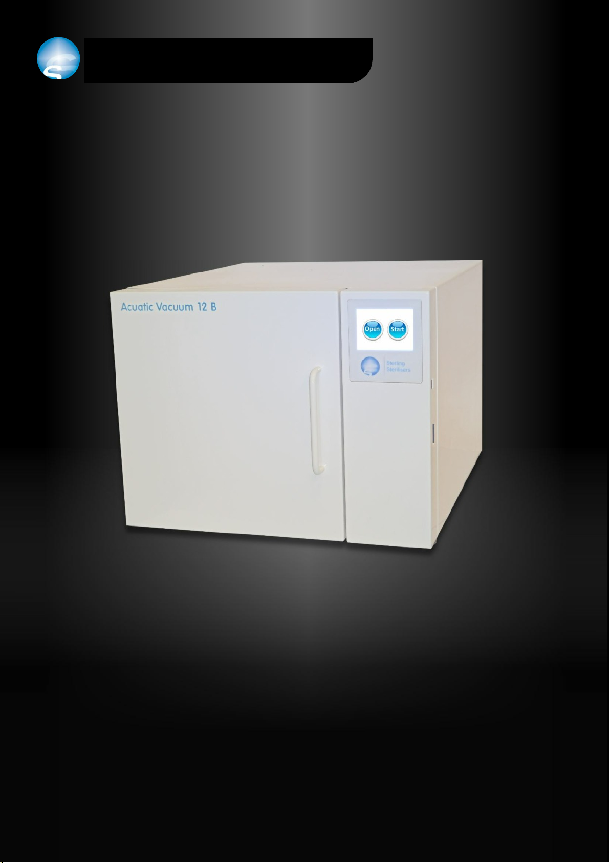
Thank you for choosing the Acuatic Vacuum 12 B steriliser from Sterling Sterilisers. We are confident that you have
purchased the finest steriliser of its type which will provide you with many years of efficient, reliable service.
Features
Fast - cycle times are between 12 and 35 minutes from start to finish not including drying - dependent on cycle
choice and loading
Simple to use - easy to understand colour touch screen display
Easy close and easy open door - push to close with vacuum assistance, touch button opening
Inbuilt Securilog data logger - to encrypt and record cycle details onto a memory card
Separate internal clean and used water reservoirs - water is only used once per cycle to ensure cleanliness
Easy to service and maintain - keeps downtime and maintenance costs to a minimum
No internal heating element - makes for easy cleaning of the chamber
N-type cycle - a fast, non vacuum cycle for solid unwrapped instruments
B-type cycle - a vacuum cycle for solid, hollow, tubular or porous loads, wrapped or unwrapped, pouched or not
Low energy consumption per cycle - keeps running costs to a minimum
Low water consumption per cycle - keeps water production or purchase costs to a minimum
No rust construction - structural parts are manufactured from stainless steel or aluminium
Impossible to overheat - innovative engineering eliminates downtime due to overheating
Easy water fill - just pour into the filling spout
Clean water auto fill - connects to an external water supply for automatic filling
Easy water drain - simple plug in drain hose
Used water auto drain - connect a tube to the rear of the steriliser for automatic draining
Self monitoring - an automatic control system continuously monitors cycle parameters to ensure effective, reliable
and complete sterilisation
Parts Supplied with the Acuatic Vacuum steriliser
These instructions
Four trays, tray rack and tray handle
Two drain tubes
Drying rack if the steriliser is supplied for use in the dental market
SD memory card and USB adaptor
Guarantee
No other steriliser manufacturer offers the security and assurance of a guarantee quite like the onesupplied by Sterling
Sterilisers. We're so confident in the quality and reliability of our product that each of our distributors provide a one
year parts and labour guarantee and a five year, fully transferable, unlimited usage parts guarantee. For full details of
the guarantee see www.sterlingsterilisers.com .
Pressure Vessel
The parts of the steriliser that are subject to steam pressure comply with the Pressure Systems Safety Regulations
2000.
1
Acuatic Vacuum steriliser
Introduction

2
Acuatic Vacuum steriliser Illustration
ABCD
E
F
G
N-type
-1
0
2
Pressure (bar)
138°C
134°C
Air removal
and heating
1
Time
Sterilising
Drying
138°C
134°C
-1
0
2
Pressure (bar)
1
Time
Air removal
and heating
Drying
Sterilising
B-type
A- door seal
B-chamber with tray rack and trays
C-water filling spout
D- touch screen display
E-clean water drain
F- used water drain
G-data logger
Cycle Charts
Pressure/time graphs are shown below for both N-type and B-type cycles.

3
Acuatic Vacuum steriliser
Safety
General Safety
Read these User Instructions carefully before using your steriliser and keep them for future
reference.
There are no user serviceable parts internally. Never remove the steriliser casing or try to
insert objects through holes or openings.
The steriliser is heavy - 23 kg. Exercise caution and seek assistance when lifting, moving or
carrying the steriliser.
Do not stack anything on top of the steriliser.
Ensure that nothing rests on the steriliser mains lead and that the mains lead is not located
where it can be stepped on or tripped over. Ensure that no part of the mains lead is under
the steriliser when in use.
Do not attempt to service the steriliser yourself. This should only be carried out by a
properly trained service engineer.
If you drop or damage the steriliser arrange to have it checked by a qualified service
engineer before you use it again.
Keep the steriliser on a flat, stable surface.
Ensure the steriliser is never used by untrained or unauthorised personnel.
The steriliser should not be kept in damp or wet conditions or in a zone of risk associated
with flammable anaesthetics.
On completion of a cycle the sterilised instruments, the internal surfaces of the steriliser
and the steriliser door may be hot. Do not touch these parts until cooling has taken place
and exercise care when handling just sterilised instruments. The tray handle should always
be used to remove trays from the steriliser.
Safety features
Electric door lock - door opening is disabled during a cycle.
Pressure door lock - door opening is disabled at all times when the pressure in the steriliser
chamber is greater than atmospheric pressure.
Pressure relief valve - prevents over pressurisation of the steriliser.
Control - the steriliser is fitted with sophisticated control software. All parameters are
constantly monitored and satisfactory completion of a cycle is not possible unless
sterilisation has taken place.
Door switch - prevents a cycle from being started unless the door is closed properly.
Overheat protection - the heating elements are self-controlling and cannot overheat.
Ambient Conditions
The steriliser is limited for use under the following conditions:-
At an ambient temperature of between 2 and 40°C
At a maximum relative humidity of 80% up to 31°C decreasing linearly to 50% at 40°C.
Processing Limitations
The steriliser should not be used to process:-
Paper except for pouches specifically designed for sterilising
Fluids
Porous items - except when using a B-type cycle
Items that are not suitable for sterilising at 134°C

Daily Maintenance
Clean the door seal using a lint free cloth and soapy water.
Check the door seal for any signs of damage and replace if necessary.
Clean the face of the chamber that the door seal closes onto.
Drain both reservoirs at the end of each day and leave empty overnight.
Daily Testing
Steam penetration test - put a TST test strip in a Helix tester. Put the Helix tester in the steriliser
and run a vacuum cycle. The test is passed if the TST test strip changes colour.
Automatic control test - run a cycle and observe. The test will be considered satisfactory if the
following requirements are met:
●the steriliser does not error at any point during the cycle
●the door cannot be opened until the cycle is complete
●a visual display of “cycle complete” occurs at the end of the cycle
●no mechanical or other anomaly is observed
Weekly Testing
Run the automatic air leakage test. This test will show that the steriliser is capable of pulling and
holding a certain level of vacuum. The display will indicate a pass or fail result at the end of the
test cycle. The test cycle is accessed from stand-by with the door open - press the “i” button, then
the “Options” button.
Servicing
Arrange to have the steriliser serviced by a trained service engineer every six months.
Annual Inspection
In order to comply with Health and Safety legislation you should arrange to have your steriliser
inspected for pressure safety by a “competent person” once a year.
Annual Testing (or Validation)
In order to check that all cycle parameters are being met you should arrange to have your
steriliser tested annually by a trained service engineer.
4
Do not permit any
person other than
qualified personnel
to supply parts for,
service or repair your
Acuatic Vacuum
steriliser.
Acuatic Vacuum steriliser
Care and Data Logger
Only use chlorine free
cleaning products.

Getting Started
Place the steriliser on a flat, level, strong, heat resistant and water resistant surface.
Ensure a clearance of 50 mm to the top and both sides of the steriliser for adequate
ventilation.
Ensure that nothing that can be affected by heat is above or behind the steriliser.
Plug into the mains. The mains plug should be easily accessible should it be necessary
to disconnect the steriliser from the mains electrical supply for any reason.
Switch the power on. The steriliser is now ready for use.
Filling
When the clean water reservoir is empty, the display will ask for the reservoir to be
filled.
To fill, pour water into the filling spout. The steriliser will be ready for use as soon as
the minimum water level in the clean water reservoir has been reached. This will be
indicated by the “Fill clean water tank” display being replaced by the time display.
Filling of the clean water reservoir can be continued until the filling spout is full.
There is also an auto fill connection on the rear of the steriliser that can be connected
to an external water supply to enable automatic filling of the steriliser.
Water Quality
The steriliser should be filled with distilled, reverse osmosis or purified water.
If the water used is low conductivity it will be acceptable. If poor quality water or
tap water is used the steriliser display will warn about water quality.
The steriliser may be used with poor quality water but this is not recommended
because of the risk of the heaters becoming scaled.
Draining
When the used water reservoir is full the display will ask for it to be drained. This will
need to be done before the steriliser will allow the next cycle to be run.
It is recommended that both water tanks are drained at the end of each working day
and left to dry overnight in order to keep the microbiological count as low as possible.
The clean water tank should then be filled at the start of the next working day.
Both water tank drains are located on the front of the steriliser. To drain either tank,
plug the drain pipe into the appropriate drain connector and allow the water to drain
into a sink or suitable container.
There is an additional used water drain connection on the rear of the steriliser. To
autodrain the used water, simply plug in a drain tube to this connection and run it to
a nearby sink or suitable container.
Options
The options menu is accessed from stand-by with the door open - press the “i” button,
then the “Options” button. The four options available are:-
1. Set drying time. This is the time that drying will run following sterilisation. It can
be set from anywhere between 0 and 60 minutes.
2. Run air leakage test. See Weekly Testing on the previous page.
3. Enable or disable autofill. Set to “Disable” for manual filling or “Enable” for
autofilling from an external water supply.
4. Enable or disable N-type cycle. Choose whether to enable or disable the N-type
cyclewhich is a fast non vacuum cycle suitable only for solid, unwrapped instruments.
5
Acuatic Vacuum steriliser
Getting Started
Fill clean
water tank
Drain used
water tank

6
Stand-by
With the door open the steriliser is in stand-by mode and will display the time, chamber
temperature and atmospheric pressure. To adjust the time displayed, press and hold
the time display and a time adjustment display will pop up.
Pressing the “i” button will display the date, cycle count information, water conductivity
information and the “Options” button from where you can adjust the amount of drying
time or run an air leakage test. To change the date press where the date is displayed
and a date adjustment display will pop up.
Pressing the orange triangle button will show the Securilog data logger display.
Pressing the “Door” button brings on the vacuum pump to assist in closing the door.
Instrument Preparation
Ensure instruments are cleaned and rinsed before sterilising. The use of a washer
disinfector or ultrasonic bath is recommended.
The perforated trays supplied with the steriliser should always be used. Paper or tray
liners that could block the tray perforations should not be used.
The drying rack should be used for processing pouched instruments.
Do not overload trays and ensure that pouches or instruments do not touch each other
or the chamber walls.
Starting a Cycle
Load the steriliser with the instruments to be sterilised.
Press the “Door” button and hold the door closed.
When the door has closed the steriliser will move to “ready” mode and the display
will show “Open” and “Start” buttons.
Pressing “Open” will open the door.
Pressing “Start” will start a cycle. If the N-type cycle is enabled you will be offered a
choice of starting N-type or B-type cycles.
Processing
When a cycle is running the display will show the cycle time elapsed, the operating
temperature and pressure and the cycle status.
When in the “Sterilising” part of the cycle a countdown timer counting down from 3
minutes will be displayed on the left hand part of the green timer bar.
Towards the end of the cycle a countdown timer will be displayed on the right hand
part of the green timer bar to countdown the last 3 minutes of the cycle before the
door can be opened.
Once a cycle has started it can only be interrupted by switching the steriliser off.
Cycle Completion
When the cycle has finished the display will show “Cycle completed”. The door can be
opened at this point by pressing the “Open” button.
If the door is not opened, drying will continue until the drying timer has timed out.
Error Messages
If the cycle should fail to complete for any reason an error message will be displayed.
Each error message is numbered and explained with a short message.
Contact your local service engineer or Sterling Sterilisers Ltd in the event of any fault
occurring. Please provide as much information as possible with regard to the problem
including the number and description of any error message displayed.
Acuatic Vacuum steriliser
Operation
135.5 C
STERILISING
2.24 bar
09:48
3:00
12:00
22.7 C 1017 mbar
Press here to display
extra information
Open Start
Cycle completed
Open
Drying time ... 25:47 -0.42 bar
Cycle time before drying... 15:32
Open
RESET
!!
Error 3
Loss of power
RESET
i
Door
Oil lubricated handpieces
must be pouched in order
to prevent oil from
entering the steriliser.

Securilog Data Logger
The inbuilt Securilog data logger securely records encrypted cycle data onto a memory
card. The cycle data can be copied to and read from a computer once the Securilog
application has been installed to that computer.
To record cycle data ensure that an SD memory card formatted with the FAT16 file system
is inserted in the steriliser. The steriliser is supplied with a suitable card fitted. If no card
is inserted or if the card is faulty or corrupted the display will flash ”Insert SD Card” when
the steriliser is in stand-by with the door closed.
To install the Securilog application to your computer, remove the SD memory card from
the steriliser following the removal procedure on the next page, insert it into the USB
adaptor provided and plug into a USB slot on your computer. The SD memory card should
appear as a “Removable Disk”. If for example the SD memory card appears as drive “D”,
open it and run the file named Securilog Installation Application.
To make the Securilog application easy to locate and run after it has been installed to your
computer, be sure to keep the “Add shortcut to desktop” checkbox ticked.
To import cycle data from the SD memory card to your computer, run the Securilog
application by double clicking the Securilog icon on your desktop. Remove the SD memory
card from the steriliser following the removal procedure on the next page, insert it into
the USB adaptor provided and plug into a USB slot on your computer.
Click on “Import Files” from within the Securilog application. The Securilog application
should automatically find the SD card and import the cycle data from the card to your
computer. If the SD card is not automatically detected, a file browser window will open.
Single click the memory card drive which is “Removable Disk (D:)” in the example shown
on the right. Then click “OK”. This will import the data from the SD card which can then
be removed from the PC and inserted back into the steriliser.
Each recorded cycle will have its own entry in the table shown below and can be clicked
on to show individual cycle detail on the right hand side of the screen which can then be
analysed and printed if required.
7
Do not remove power
or take the SD memory
card out of the steriliser
when it is running a
cycle. If you do, this
may result in corruption
of the data on the
memory card.
Acuatic Vacuum steriliser
Securilog Data Logger

Securilog SD memory card
The SD memory card that is supplied with your steriliser is used to store documentation
and cycle data that is recorded from the inbuilt Securilog data logger.
To remove the SD memory card from the steriliser the following procedure should be
followed to ensure that the card can be removed safely with no risk of data corruption.
Open the steriliser door. Press the “orange triangle” Securilog button to access the
Securilog display.
The “Securilog LED” should be green, indicating that the SD card is inserted and ready to
record. Press the “Securilog Button” and wait for the “Securilog LED” to go white. The SD
card can then be removed safely.
The SD card contains the following pdf files which can be read or printed:-
1. These User Instructions.
2. A Written Scheme of Examination for compliance with the Pressure Systems Safety
Regulations 2000.
3. An Inspection Certificate to confirm that the steriliser has been designed,
manufactured and tested in accordance with the Medical Devices Directive.
4. A Product Registration and Customer Survey form. Please take the time to print this
out, complete it and return it to Sterling Sterilisers so that we can keep our records
up to date and use your feedback to further develop our product to better suit
future needs.
The SD card also contains the Securilog Installation Application which is used to install the
Securilog application to your computer as described on the previous page plus the
associated Securilog Data Logger Application Files.
Finally, the SD card contains a Logbook folder which contains both spreadsheet and pdf
versions of the steriliser logbook which can be used to record the steriliser details and
ongoing maintenance, testing and inspection records.
The SD card should be reinserted into the steriliser prior to running the next cycle to ensure
that no data goes unrecorded. On reinsertion the “Securilog LED” should go green
indicating once again that the SD card is inserted and ready to record.
8
Ensure that the tab on
the SD memory card is
not in the “Lock”
position as this will
prevent the card from
recording cycle data.
Acuatic Vacuum steriliser
Securilog Data Logger

Made in UK
Notified Body
* Cycle time and exact electrical and water usage per cycle is dependent on cycle type, loading and cycle start
temperature. Cycle times quoted do not include drying which can be set to anywhere between 0 and 60 minutes.
Feature
Dimensions Width 425 mm
Height 340 mm
Length 500 mm
Weight 23 kg
Chamber diameter 218 mm
Chamber length 320 mm
Chamber volume 12 litres
Trays Number 4
Width 183 mm
Length 284 mm
Maximum loading per tray 1.5 kg
Sterilising Temperature 134°C to 138°C
Time 3 minutes 30 seconds minimum
Cycle time 12 to 30 minutes*
Cycle types N-type non vacuum For solid unwrapped instruments.
B-type vacuum For porous, tubular or hollow items, wrapped, pouched or not.
Limits Design pressure -1 to 3 bar
Design temperature 2 to 144°C
Water Water used per cycle 200 to 700 ml*
Clean water reservoir volume 2 litres
Used water reservoir volume 2 litres
Filling Through filling spout at front or auto fill connection at rear
Draining Through drain connection at front or auto drain at rear
Certification Council Directive 93/42/EEC Medical Devices
Cycle Recording Type Inbuilt “Securilog” data logger
Recording media SD Memory card
Memeory card capacity Lifetime of steriliser
Clearances Top and sides 50 mm
Rear None required
Display Between 0 and 150°C ± 2°C
Accuracy Between 134 and 138°C +0 / -1.5°C
Display Temperature 0.1°C
Resolution Pressure 0.01 bar
Electrical Voltage 230 V ac ± 10%
Current Variable up to 13 A
Power Variable up to 3 kW
Frequency 50 Hz
Plug top fuse 13 A
Internal fuse 1 A
Energy used per cycle 0.2 to 0.7 kWh*
Table of contents