Stern Engineering TRENDY FOAM Product manual

1
TOUCH FREE DECK MOUNTED FOAM SOAP DISPENSERS
БЕСКОНТАКТНЫЙ НАСТОЛЬНЫЙ ДОЗАТОР МЫЛЬНОЙ ПЕНЫ
РУКОВОДСТВО ПО МОНТАЖУ И ЭКСПЛУАТАЦИИ
InstallatIon and maIntenance guIde
GREEN 28 FOAM
TRENDY FOAM ELITE FOAM

1
INDEX TECHNICAL DATA
The information in this document reflects products at the date of printing. Stern Engineering Ltd reserves the right, subject to all applicable laws, at any time, at its sole discretion, and
without notice, to discontinue or change the features, designs, materials and other specications of its products, and to either permanently or temporarily withdraw any of the forgoing from
the market. All information in this document is provided “as is” without warranty of any kind, either expressed or implied, including but not limited to any implied warranties of merchant-
ability, tness for a particular purpose, or non-infringement. Stern Engineering Ltd assumes no responsibility for errors or omissions in the information presented in this document. In no
event shallStern Engineering Ltd be liable for any special, incidental, indirect or consequential damages of any kind, or any damages whatsoever arising out of or in connection with the use
or performance of this information. The tradenames, trademarks, logos and service marks presented in this document, including their design, are the property of Stern Engineering Ltd or
other third parties and you are not permitted to use them without the prior written consent of Stern Engineering Ltd or such third party as may own them.
GREEN 28 FOAM E
TRENDY FOAM E
ELITE FOAM E
Capacity Liter \. oz.
Power Supply V transformer
Soap viscosity up to cPs
Standard discharge Varies according to viscosity and soap consistency
Sensor range mm +/ mm /..” customizable by optional
remote control)
TECHNICAL DATA
PRE-INSTALLATION INFO
PACK CONTENTS
INSTALLATION
FILLING THE SOAP TANK
SETTINGS ADJUSTMENT
SPARE PARTS LIST
MAINTENANCE
WARRANTY
TROUBLESHOOTING

2 3
PRE-INSTALLATION INFO PACK CONTENTS
Check contents
Separate all parts from the packaging and check each part with the “Pack contents” section.
Make sure all parts are accounted for before discarding any packaging material.
If any parts are missing, do not attempt to install your touch free soap dispenser until you obtain the
missing parts.
Warnings
Do not install your electronic soap dispenser facing a mirror or any electronic system operated by an
infrared sensor.
To prevent reflection problems, it is recommended to keep a minimum distance of ’ (.m)
between the soap dispenser sensor and any other directly facing objects and
a minimum of 6” ( mm) between the soap dispenser and the adjacent faucet.
IMPORTANT: Keep in mind that when using the faucet installed next to the soap
dispenser, the user hands should not interfere with the soap dispenser sensor
detection area.
Familiarize yourself with the part names and ensure that all the parts are included in
your package.
1 X FOAM DISPENSER bODY
1 X FOAM COMPRESSOR wITH PIPE
1 X PUMP ASSEMbLY
wITH bOTTLE SUPPORT
AND SOAP TANK
2 SCREwS AND
2 ANCHORS
12V TRANSFORMER
CORRECT INSTALLATION INCORRECT INSTALLATION
DO NOT AIM SOAP SENSOR
AT WATER STREAM
Stern foam soap dispensers, with proper care, will provide long term trouble free service.
Quality liquid soap ofrecommendedviscosity and pH levels are the main factors for smooth operation
of your dispenser. If needed, use a viscometer to verify the viscosity of your soap to ensure maximum
benet. The recommended range for foam soap viscosity is up to cPs. Thicker liquid soap flows
slower and inhibits the pump valve, causing strain and damage.
Stern foam soap dispensers are suitable for use with any generic liquid soap of the correct viscosity
and pH. The pH level of all soap used in Stern foam soap dispensers should be between . to ..
Lower levels will cause corrosion to the metal dispenser and even the rubber and plastic components.
Higher pH levels will cause swelling to rubber parts and degradation of plastic components over time.
4 5
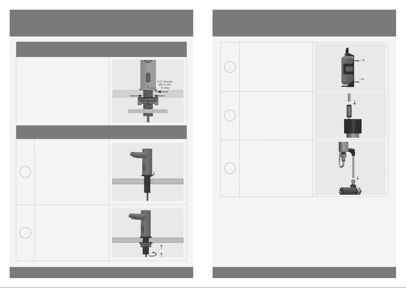
STEP 1 – REMOVE ALL MOUNTING HARDwARE
For TRENDY/ELITE Foam Dispensers:
Drill a hole (mm) in the deck or lavatory
for the soap dispenser body and a small hole
() for the anti rotation pin.
For GREEN Foam Dispenser:
Drill a hole () in the deck or lavatory for
the soap dispenser body.
Disassemble the nut, disk and gasket from the
base of the soap dispenser body.
/” diameter
(Ø X /”
deep
Recommended hole size
”
[Ø ]
3/4”
[19.3]
STEP 2 – INSTALLING THE SOAP DISPENSER
Insert the soap dispenser body and
the anti rotation pin along with the
rosette into the holes drilled.
Under the deck, secure the gasket,
disk and nut over the soap dispenser
body nipple.
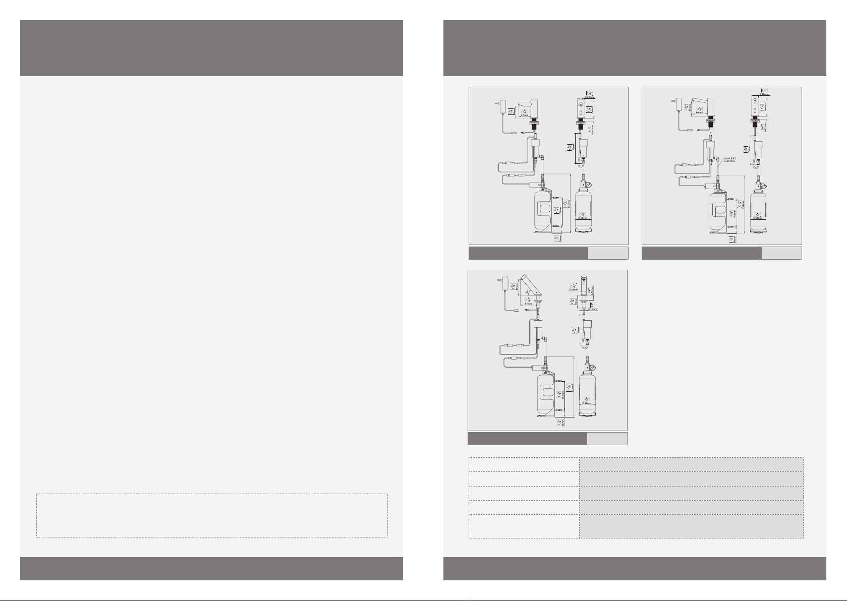
INSTALLATION
INSTALLATION
Fix the bottle support to the desired
location. The pump MUST be within
reach range of the Com cable and
black supply tube.
Connect the pipe from the dispenser
to the quick connection tting of the
compressor. Make sure it is rmly
plugged in.
Connect the second soap tube
provided in the packaging from
the compressor to the quick
connection tting at the top of the
soap dispenser pump assembly by
snapping it in.

6 7
STEP 3 – CONNECTING THE POwER SOURCE
Remove the protective sticker
covering the sensor.
Connect the soap dispenser pump
connector to its matching connector
on the electronic unit. Please
note that since the connector is
waterproof, some pressure must be
applied for a perfect seal.
O-RING VISIBLE –
NOT CONNECTED PROPERLY
ONLY THE GROOVES ARE VISIBLE –
CONNECTED PROPERLY
IMPORTANT: the contacts connector should be connected properly so that the white
o-ring is not visible and a clicking sound is heard.
PAY ATTENTION: If the contacts connectors are not connected properly, the soap
dispenser pump will not operate properly.
Plug the transformer into the
electricity socket and connect the
transformer connector FROM THE TRANSFORMER TO THE SOAP DISPENSER
Wait about seconds before
placing your hands in the sensor
range to avoid adjustment mode. 10
SECONDS
ABOUT
If your model is an MF model, please refer to the Multifeed installation guide.
INSTALLATION FILLING THE SOAP TANK
1Unscrew the soap tank from the pump assembly and
pull it out from the bottle support.
2Fill the bottle with liquid soap to the top line. Make
sure the bottle is clean before lling it with soap.
3Insert the bottle back into the bottle support.
4Screw the soap tank back into the pump assembly.
Make sure the tank is rmly secured into place.
5
Press and hold the rell button located at the back of
the pump assembly until soap is dispensed from the
soap dispenser spout.
Release the button once soap begins dispensing from
the spout.
Alternately, use the FILL function on the remote
control (if available). see page .
NOTE: When the soap in the soap tank reaches the
bottom line, the tank needs to be relled.
To rell the soap tank please refer to steps .

8 9
SPARE PARTS LIST
Seals & Screws Kit Elite/Trendy Foam
Seals & Screws Kit Green Foam
-Pack Sensor Kit Elite/Trendy Foam
-Pack Sensor Kit Green Foam
Soap Dispenser Pump
Pump+Compressor Kit
6-pack Soap Bottle L
pack L Bottle Support KIt
V Transformer (EU)
V Transformer (UK)
V Transformer (US)
V Transformer (AU)
Remote Control for Foam Dispenser (Optional)
Soap & Water Remote Control (Optional)
SETTINGS ADJUSTMENT wITH A REMOTE CONTROL
If available, the foam dispenser remote control can adjust the dispenser’s settings. To
use the remote control hold it in front of the sensor at a distance of 10-15cm (4-6”).
Attention: The remote control will not operate out of the recommended range (too close
or too far).
The remote control can be used to adjust the following functions:
1-SOAP QUANTITY
Press the + sign on the SOAP button to increase the soap quantity by increasing the
dispensing time. Press the - button to decrease it.
Indication: continuous blinking blue light in the sensor eye.
2-AIR QUANTITY
To improve soap consistency (“foamability) change the amount air to be mixed. Press the
+ sign on the AIR button to increase the air quantity and the - to
decrease it.
Indication: blinks of the blue light in the sensor eye.
3-RES
This function resets the sensor back to its factory settings.
4-TEMPORARY OFF FUNCTION
This function temporary disables the
dispenser. Use this function to preform
maintenance in front of the sensor without
activating the system (for example: cleaning).
The soap dispenser will shut o for one minute
aer this button is pressed once.
To return to normal operation before the
minute is over, press the On/O button again.
5-FILL THE SOAP TANK
Once the soap tank has been lled \ relled,
press the FILL button. The pump will run for
one minute, priming the piping with soap.
Once soap begins dispensing from the spout,
priming is complete. press the FILL button
again to stop the priming before the minute is
over.
Indication: continuous solid blue light in the
sensor eye.
Care and cleaning of chrome and special nishes
DO NOT use steel wool or cleansing agents containing alcohol, acid, abrasives, or their like. Use of
any prohibited cleaning or maintenance products or substances could damage the surface of the soap
dispenser. For surface cleaning use ONLY soap and water, then wipe dry with a clean cloth or towel. When
cleaning bathroom tiles, the soap dispenser should be protected from any splattering of harsh cleansers.
Disassemble of the soap pipe from the pump
The soap pipe can be disconnected from the soap pump by a simple slide & pull action. The sliding ring of
the quick connection xation nipple on the pump should be pulled down. It releases the open end of the
soap pipe which can then be easily pulled out.
Filter cleaning instructions (foam dispenser only)
This soap dispenser is provided with a foam lter. It is recommended to clean the lter every six () months.
If the soap supply has decreased, this may be caused by the clogged lter. The lter can be cleaned as
follows:
. Use a wrench to unscrew the quick connection tting from the foam compressor and pull out the
lter housing.
. Remove the lter from the housing.
. Replace the lter (recommended) or wash it under running water for a temporary x.
. Reassemble the parts.
Clean the soap tank
Clean out the tank prior to rell by flushing warm water through the hoses and pump until clean water is
released from the spout. TIP: Keeping a spare tank will enable this process to be completed in a speedy and
hygienic manner with minimal downtime.
MAINTENANCE
10 11
LIMITED wARRANTY
Y. Stern Engineering Ltd. warrants that its electronic products will be free of defects in
material and workmanship during normal use for two years from the date the product is
purchased.
If a defect is found in normal use, Y. Stern Engineering Ltd. will, at its discretion, repair,
provide a replacement part or product, or make appropriate adjustments. Damage caused
by accident, misuse, or abuse is not covered by this warranty. Improper care and cleaning
will void the warranty. Proof of purchase (original sales receipt) must be provided to Stern
Engineering Ltd. with all warranty claims.
Stern Engineering Ltd is not responsible for labor charges, installation, or other incidental
or consequential costs other than those noted above. In no event shall the liability of Stern
Engineering Ltd. exceed the purchase price of the product.
If you believe that you have a warranty claim, contact your Stern Distributor, Dealer or
Plumbing Contractor. Please be sure to provide all pertinent information regarding your
claim, including a complete description of the problem, the product, model number,
the date the product was purchased, from whom the product was purchased and the
installation date. Also include your original invoice.
Y. STERN ENGINEERING AND/OR SELLER DISCLAIM ANY LIABILITY FOR SPECIAL, INCIDENTAL
OR CONSEQUENTIAL DAMAGES. This warranty excludes product damage due to installation
error, incorrect maintenance, wear and tear, battery, product abuse, or product misuse,
whether performed by a contractor, service company, or the consumer. This warranty does
not cover product damage caused by the following:
- Incorrect installation.
- inversions of supply pipes.
- Pressures or temperatures exceeding recommended limits.
- Improper manipulation, tampering, bad or lapsed maintenance.
- Foreign bodies, dirt or scale introduced by the water supply or soap tank.
- Use of the soap outside of viscosity specications.
- Alteration of the original soap/foam dispenser components (including pipes).
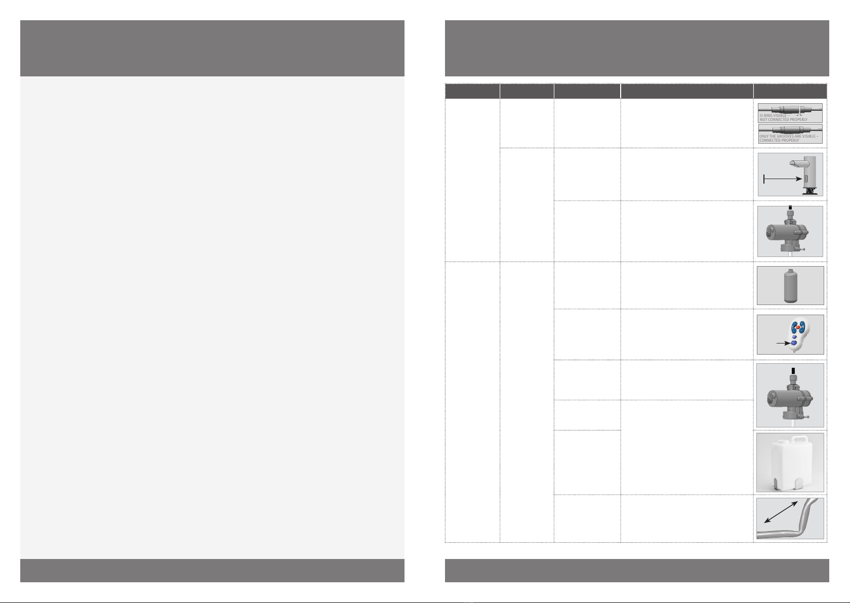
TROUbLESHOOTING
IllustrationSolutionCauseInvestigationIndication
O-RING VISIBLE –
NOT CONNECTED PROPERLY
ONLY THE GROOVES ARE VISIBLE –
CONNECTED PROPERLY
The connector should be inserted fully
until white o-ring is not visible. Remove
the o-ring if necessary
AUX connector not
fully inserted
Continuous
discharge from
the nozzle
False
activation:
Foam
dispensing
Min . M
Eliminate any cause of reflection and if
necessary use appropriate remote control
to shorten detection range.
Reflection issue
from other object
Random
discharge from
the nozzle
Replace the Pump. Rinse warm water
through the pipe and the body of the
soap dispenser all the way to the nozzle.
Soap discharging
from pump
housing.
Fill with soap with correct viscosity
(up to cPs) and prime pipes using the
ll button on remote control.
Soap tank is
empty.
Pump and
compressor
are making a
sound when
sensor is
activated
Foam not
dispensing
Press
FILL
Button
Prime the soap dispenser by pressing the
ll button on the remote or by pressing
the rell button located at the bottom of
the pump, until foam exits the nozzle.
Soap dispenser has
not been primed
Replace the pump.Damaged pump
(discharge from
housing)
Run warm water through pipe, pump, and
body all the way to the nozzle. Replace
with soap of correct viscosity. NOTE:
Using the soap dispenser with high
viscosity soap may cause permanent
damage to the pump and shorten the
lifecycle.
Debris or dried
soap in the pipe
or tank
Soap Viscosity
up to cPs)
High viscosity soap
(>100 cPs)
Unbend or straighten pipes.Bent pipes

12 13
TROUbLESHOOTING
IllustrationSolutionCauseInvestigationIndication
Replace the pump.Damaged pumpPump is making a
sound when sensor
is activated, but
the compressor is
not.
Foam not
dispensing
O-RING VISIBLE –
NOT CONNECTED PROPERLY
ONLY THE GROOVES ARE VISIBLE –
CONNECTED PROPERLY
Insert fully, remove the O ring if
necessary
AUX connector
not fully inserted
Compressor is making
a sound when sensor
is activated, but the
pump is not.
Replace the pump.Damaged Pump
O-RING VISIBLE –
NOT CONNECTED PROPERLY
ONLY THE GROOVES ARE VISIBLE –
CONNECTED PROPERLY
The connector should be inserted
fully until the white o-ring is
not visible. Remove the o-ring if
necessary
AUX connector
not fully inserted
Sensor is
blinking
when hand
is placed
in front
Pump
is not
making
sound
when the
sensor is
activated
Foam not
dispensing
Press
Replace the Pump. Rinse warm
water through the pipe and the
body of the soap dispenser all the
way to the nozzle.
Rell button
on pump does
not activate the
pump.
Damaged pump
(discharge from
housing).
Run warm water through pipe,
pump, and body all the way to
the nozzle. Replace with soap of
correct viscosity. NOTE: Using the
soap dispenser with high viscosity
soap may cause permanent
damage to the pump and shorten
the lifecycle.
Debris or dried
soap in the tank
or tubing
IllustrationSolutionCauseInvestigationIndication
Press
Transformer: Check operation
with functioning transformer.
Where necessary replace
with appropriate transformer.
For part numbers see spare
parts list.
Rell button on
pump does not
activate the pump.
Sensor is
not blinking
when hand
is placed in
front
Pump is
not making
sound when
the sensor is
activated
Foam not
dispensing
Min . M
Eliminate any cause
of reflection and use
appropriate remote control to
shorten detection range.
Reflection issue
from other object
Replace
sensor
If the above two solutions
have not resolved this issue
replace with appropriate
sensor. For part numbers see
spare parts list.
Damaged sensor
. Increase the air to soap
ratio.
Liquid rather than
foam is being
dispensed out of
the nozzle
Foam not dispensing
. Verify that the lter is
clean.
. Replace compressor
(supplied with pump). For
part numbers see spare
parts list.
Use remote to decrease soap
volume by pressing the "-
Soap" key.
Foam dosage is too
large
Foam is dispensing
Use remote to increase soap
volume by pressing the "+
Soap" key.
Foam dosage is too
small
Use remote to decrease the
amount of air in the foam by
pressing the "- Air" Key.
Foam is too dense
Use remote to increase the
amount of air in the foam by
pressing the " + Air" key.
Foam is too
liqueed
TROUbLESHOOTING
14 15
СОДЕРЖАНИЕ
The information in this document reflects products at the date of printing. Stern Engineering Ltd reserves the right, subject to all applicable laws, at any time, at its sole discretion, and
without notice, to discontinue or change the features, designs, materials and other specications of its products, and to either permanently or temporarily withdraw any of the forgoing from
the market. All information in this document is provided “as is” without warranty of any kind, either expressed or implied, including but not limited to any implied warranties of merchant-
ability, tness for a particular purpose, or non-infringement. Stern Engineering Ltd assumes no responsibility for errors or omissions in the information presented in this document. In no
event shallStern Engineering Ltd be liable for any special, incidental, indirect or consequential damages of any kind, or any damages whatsoever arising out of or in connection with the use
or performance of this information. The tradenames, trademarks, logos and service marks presented in this document, including their design, are the property of Stern Engineering Ltd or
other third parties and you are not permitted to use them without the prior written consent of Stern Engineering Ltd or such third party as may own them.
ТЕХНИЧЕСКИЕ ХАРАКТЕРИСТИКИ
GREEN 28 FOAM E
TRENDY FOAM E
ELITE FOAM E
Объём мл
Напряжение питания Адаптер В
Soap viscosity до Па·с
Объём порции мыла в зависимости от вязкости жидкого мыла
Зона срабатывания
ИК-датчика
мм +/ мм (регулируется при помощи пульта
дистанционного управления)
ТЕХНИЧЕСКИЕ ХАРАКТЕРИСТИКИ
ПРЕДУСТАНОВОЧНАЯ ИНФОРМАЦИЯ
КОМПЛЕКТ ПОСТАВКИ
МОНТАЖ
ЗАПРАВКА РЕЗЕРВУАРА
РЕГУЛИРОВКА ПАРАМЕТРОВ ПРИ
ПОМОЩИ ПУЛЬТА ДИСТАНЦИОННОГО
УПРАВЛЕНИЯ
ПЕРЕЧЕНЬ ЗАПАСНЫХ ЧАСТЕЙ
ТЕХНИЧЕСКОЕ ОБСЛУЖИВАНИЕ
УСЛОВИЯ ГАРАНТИИ
ПОИСК И УСТРАНЕНИЕ НЕИСПРАВНОСТЕЙ

16 17
ПРЕДУСТАНОВОЧНАЯ ИНФОРМАЦИЯ
Проверка комплектации
После извлечения дозатора из упаковки обратитесь к стр. 3 и убедитесь в его полной
комплектации. Выпишите серийный номер дозатора, указанный на упаковке,
прежде чем выбрасывать упаковку. В случае отсутствия каких-либо деталей комплектации
воздержитесь от установки дозатора до получения недостающих деталей.
Предостережения
Автоматический дозатор не следует монтировать напротив зеркала или других электронных
приборов, управляемых ИК-датчиком.
С целью предотвращения проблем, связанных с отражением, рекомендуется соблюдение
минимального расстояния в . метра между дозатором и любыми другими предметами, а также
минимум 150 мм между дозатором и установленным поблизости смесителем.
Важное замечание: Помните, что руки пользователя при использовании
смесителя, находящегося поблизости, не должны находиться в зоне действия
ИК-датчика дозатора.
ПРАВИЛЬНЫЙ МОНТАЖ НЕПРАВИЛЬНЫЙ МОНТАЖ
НЕ НАПРАВЛЯЙТЕ ИК-ДАТЧИК ДОЗАТОРА
В СТОРОНУ СТРУИ ОТ СМЕСИТЕЛЯ
При правильном применении дозаторов для мыльной пены Stern и соблюдении приведенных далее
указаний и рекомендаций производителем гарантируются их долговечность и электромеханическая
надежность. Качественное жидкое мыло в пределах рекомендованной вязкости и уровня pH - основные
условия оптимальной эксплуатации вашего дозатора. При необходимости используйте вискозиметр для
проверки вязкости вашего мыла. Рекомендуемый диапазон вязкости мыла для пены- до 100 Па-с. Более
густое мыло медленнее протекает по трубкам и может заблокировать клапан насоса, вызывая деформацию
и повреждение.
Дозаторы для мыльной пены Stern пригодны для использования с любым обычным жидким мылом с
правильной вязкостью и уровнем рН. Уровень pH мыла, используемого в дозаторах Stern, должен составлять
от 6,5 до 8,5 pH. Более низкие уровни pH могут привести к коррозии металлических деталей дозатора, и даже
в его резиновых и пластмассовых компонентах.
Более высокие уровни pH могут вызвать уплотнение резиновых деталей и деформацию пластмассовых
компонентов с течением времени.
КОМПЛЕКТ ПОСТАВКИ
Ознакомьтесь с наименованием деталей и убедитесь в полной комплектации
вашего дозатора.
1 Х КОРПУС
1 X КОМПРЕССОР С ТРУБКОЙ
1 Х НАСОС И
РЕЗЕРВУАР С
ДЕРЖАТЕЛЕМ
2 Х ДЮБЕЛЯ
2 Х ШУРУПА
АДАПТЕР 12В

18 19
ШАГ 1 - СНИМИТЕ КРЕПЕЖНЫЕ ДЕТАЛИ
Для моделей Trendy/Elite: Просверлите в
столешнице или раковине отверстие 25-29
мм для корпуса и небольшое отверстие 4 мм
для штифта, предотвращающего вращение.
Для модели Green 28: Просверлите в
столешнице или раковине отверстие 20-24
мм для корпуса.
Снимите гайку, шайбу и прокладку с
основания корпуса дозатора.
/” diameter
(Ø X /”
deep
Рекомендуемый размер отверстий
”
[Ø ]
3/4”
[19.3]
ШАГ 2 - УСТАНОВКА ДОЗАТОРА
Вставьте корпус дозатора вместе с
декоративной розеткой (и штифтом)
в монтажное отверстие
столешницы или раковины.
Под столешницей/раковиной
наденьте прокладку, шайбу и гайку
на корпус дозатора и закрепите их.
МОНТАЖ МОНТАЖ
Закрепите держатель резервуара
в желаемом месте. Насос должен
находиться не дальше расстояния,
предусмотренного длиной трубки
и соединительного кабеля,
выходящих из дозатора
Закрепите трубку, выходящую из
дозатора к компрессору, вставив её
в быстрый соединитель. Убедитесь,
что трубка прочно вставлена.
Вставьте вторую трубку из
комплекта между компрессором
и угловым быстрым соединителем
насоса.

20 21
ШАГ 3 - ПОДКЛЮЧЕНИЕ ПИТАНИЯ
Удалите защитную наклейк у с
ИК-датчика. Убедитесь, что в зоне
его действия нет людей или других
объектов.
Подсоедините коннектор от
ИК-датчика к соотетствующему
коннектору компрессора.
Подсоедините коннектор от
компрессора к соответствующему
коннектору насоса.
Обратите внимание, поскольку
коннекторы водонепроницаемые,
необходимо применить некоторое
усилия для их более плотного
соединения.
УПЛОТНИТЕЛЬНОЕ КОЛЬЦО ВИДНО -
НЕПРАВИЛЬНОЕ СОЕДИНЕНИЕ
ВИДЕН ТОЛЬКО ПАЗ - ПРАВИЛЬНОЕ СОЕДИНЕНИЕ
ВАЖНОЕ ЗАМЕЧАНИЕ: Все соединительных кабеля должны быть подключены
должнымобразом до щелчка и так чтобы скрыть белое уплотнительное кольцо.
ОБРАТИТЕ ВНИМАНИЕ: Если соединительных кабеля подключены некорректно,
система не будет работать в нормальном режиме.
Вставьте адаптер питания в розетку
электрической сети и подключите
соответствующие коннекторы. ОТ АДАПТЕРА К ДОЗАТОРУ
Подождите около секунд,
прежде чем поднести руки к
дозатору в зоне действия его ИК-
датчика. 10
секунд
Если ваша модель дозатора предназначена для мультифида, обратитесь к руководству
для мультифидных дозаторов.
МОНТАЖ ЗАПРАВКА РЕЗЕРВУАРА
1
Отвинтите резервуар для мыла от
перистальтического насоса и выньте его из
держателя.
2
Наполните ёмкость жидким мылом до верхней
отметки. Перед наполненим убедитесь в чистоте
резервуара.
3Вставьте ёмкость обратно в держатель.
4
Соедините резервуар для мыла с
перистальтическим насосом. Убедитесь,
что ёмкость хорошо закреплена.
5
Нажмите и удерживайте кнопку rell,
расположенную на задней части насоса, пока не
начнется подача мыла из носика дозатора.
Данная операция также может быть осуществлена
с помощью кнопки rell на пульте дистанционного
управления для дозаторов.
Внимание: Как только мыло в резервуаре достигает
нижней отметки, резервуар необходимо вновь
наполнить. Для наполнения, пожалуйста, следуйте
пунктам .

22 23
ПЕРЕЧЕНЬ ЗАПАСНЫХ ЧАСТЕЙ
РЕГУЛИРОВКА ПАРАМЕТРОВ ПРИ ПОМОЩИ ПУЛЬТА
ДИСТАНЦИОННОГО УПРАВЛЕНИЯ
При наличии, используйте пульт дистанционного управления для настройки
параметров. Держите пульт дистанционного управления прямо перед ИК-датчиком
дозатора на расстоянии см.
Внимание: Пульт дистанционного управления не функционирует вне
рекомендованной дистанции (слишком близко или слишком далеко от ИК-датчика).
Пульт можно использовать для настройки следующих функций:
1-ОБЪЕМ МЫЛА В ПОРЦИИ
Нажмите + на кнопке SOAP, чтобы увеличить объем мыла в порции. Нажмите - на
кнопке SOAP, чтобы уменьшить объем.
Индикация: постоянное мигание светодиода ИК-датчика.
2-ОБЪЕМ ВОЗДУХА
Для улучшения “пенности” мыла измените объем воздуха в порции. Нажмите + на
кнопке AIR, чтобы увеличить объем воздуха в порции, и -, чтобы уменьшить его.
Индикация: двойное мигание светодиода ИК-датчика.
3-СБРОС
Данная функция позволяет вернуться к заводским настройкам.
4-ВРЕМЕННОЕ ОТКЛЮЧЕНИЕ
Данная функция временно отключает
дозатор. Функция применяется во время
технического обслуживания, уборки или
других действий в зоне действия ИК-датчика
без включения системы. Дозатор останется
выключенным в течение 1 минуты
при одном нажатии на данную кнопку. Для
отмены функции и возвращения в обычный
режим эксплуатации нажмите снова на
кнопку On/O или подождите одну минуту.
5-НАПОЛНЕНИЕ РЕЗЕРВУАРА
После повторного Наполнения резервуара
для мыла, нажмите на кнопку FILL.
Перистальтический насос активируется на
одну минуту для того, чтобы начать подачу
мыла из носика дозатора. Для остановки
данного процесса, повторно нажмите на
кнопку FILL.
Индикация: продолжительное горение
светодиода ИК-датчика.
Комплект прокладок и шурупов для моделей Elite/Trendy Foam
Комплект прокладок и шурупов для модели Green Foam
Комплект из 10 ИК-датчиков для моделей Elite/Trendy Foam
Комплект из 10 ИК-датчиков для модели Green Foam
Перистальтический насос
Комплект насоса и компрессора
Комплект из 6 резервуаров 1000мл
Комплект из 6 держателей для резервуара
Адаптер В
Пульт дистанционного управления для дозаторов мыльной пены
(опциональный)
Пульт дистанционного управления для дозаторов и смесителей
(опциональный)
Уход и очистка хромированных и других специальных покрытий.
НЕ применяйте стальную вату, абразивы или детергенты, содержащие алкоголь,
кислоту и т.д. Использование любых запрещенных моющих средств или материалов может повредить
поверхность дозатора. Для очистки поверхности дозатора используйте ТОЛЬКО мыло и воду, и
вытирайте сухой чистой тряпкой или полотенцем. При мытье кафеля в ванной комнате, дозатор должен
быть защищен от брызг моющих средств.
Отсоединение трубки от насоса
Остоединить трубку от насоса можно простым действием. Опустите подвижную часть быстрого
соединителя. Это освободит конец трубки, и ее можно будет легко вытащить из соединителя.
Инструкции по очистке фильтра (только для дозаторов мыльной пены)
Этот дозатор оборудован специальным фильтром. Рекомендуется прочищать фильтр каждые 6 месяцев.
Если объем мыла при подаче уменьшился, причина может быть в засоренном фильтре. Прочистить
фильтр можно следующим образом:
1. При помощи гаечного ключа открутите быстрый соединитель от компрессора и выньте корпус с
фильтром.
2. Выньте фильтр из корпуса.
3. Замените фильтр (рекомендуется) или промойте его в проточной воде в качестве временной меры.
4. Соберите фильтр и его корпус обратно и закрутите быстрый соединитель компрессора.
Очистка резервуара для мыла
Перед заполнением ёмкости мылом промойте её, пропустив проточную воду через трубки и насос до
тех пор, пока из носика дозатора не потечет чистая вода. Рекомендуется иметь запасной резервуар,
чтобы сэкономить время при эксплуатации.
ТЕХНИЧЕСКОЕ ОБСЛУЖИВАНИЕ

24 25
ГАРАНТИЯ
Производитель обеспечивает двухлетнюю гарантию с момента приобретения на изделия при
нормальной эксплуатации изделий. При обнаружении повреждения в условиях нормального
использования компания-производитель по своему усмотрению обеспечит ремонт или замену
детали или изделия или же
осуществит необходимые настройки. Повреждение, причиненное в результате
аварии или неправильной эксплуатации, не покрывается данной гарантией.
Ненадлежащий уход или очистка приводят к отмене гарантии. Доказательство осуществления
покупки (оригинальный чек) должно быть предоставлено компании Stern Engineering Ltd. вместе
с подаваемой претензией по гарантии.
Компания Stern Engineering Ltd. не несет ответственности за стоимость
трудозатрат, установку или за другие косвенные стоимости, кроме упомянутых выше. Ни при каких
условиях денежные обязательства компании Stern Engineering Ltd. не превысят цены фактической
продажи смесителя, смывного
устройства или душевой системы. Если вы считаете, что у вас есть основания на предъявление
претензии по гарантии, свяжитесь с дистрибьютором компании
Stern, вашим агентом по продаже или с подрядчиком. Пожалуйста, предоставьте всю информацию,
относящуюся к вашей претензии, включая полное описание
возникшей проблемы, изделия, номер модели, дату производства, дату приобретения продукта,
данные продавца и дату установки. Кроме того, приложите оригинал оплаченного вами
счета. ПРОИЗВОДИТЕЛЬ И /ИЛИ ПРОДАВЕЦ НЕ НЕСУТ ОТВЕСТВЕННОСТИ И НЕ БЕРУТ НА СЕБЯ
ОБЯЗАТЕЛЬСТВ ЗА ОСОБЫЕ, СЛУЧАЙНЫЕ ИЛИ КОСВЕННЫЕ ПОВРЕЖДЕНИЯ.
Данная гарантия исключает причиненные подрядчиком, обслуживающей фирмой или
пользователем повреждения изделия в результате некорректной
установки, некорректного технического обслуживания, амортизации, состава воды или
неправильной эксплуатации изделия. Данная гарантия не покрывает повреждения, причиненные
изделию в следующих случаях:
- Некорректная установка,
- Замена подводок и трубок
- Эксплуатация изделия при давлении и в температурах, превышающих рекомендованные.
- Некорректное использование, нанесение повреждений, плохое или недостаточное техническое
обслуживание.
- Попадание посторонних предметов, мусора или накипи через подачу воды или мыла.
- Использование мыла вне рекоммендованной вязкости.
- Замена заводских компонентов (включая трубки).
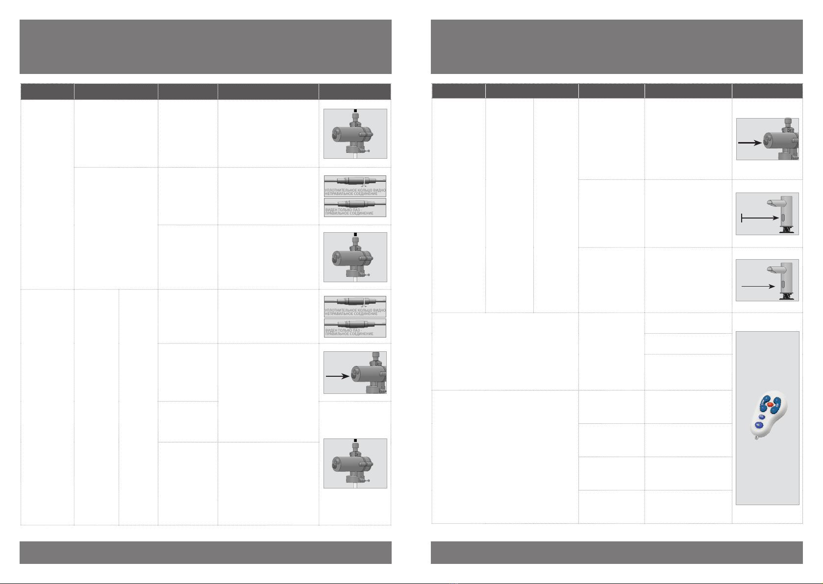
ПОИСК И УСТРАНЕНИЕ НЕИСПРАВНОСТЕЙ
IllustrationSolutionCauseInvestigationIndication
УПЛОТНИТЕЛЬНОЕ КОЛЬЦО ВИДНО -
НЕПРАВИЛЬНОЕ СОЕДИНЕНИЕ
ВИДЕН ТОЛЬКО ПАЗ -
ПРАВИЛЬНОЕ СОЕДИНЕНИЕ
Коннектор должен быть вставлен
полностью, пока белое уплотнительное
кольцо не станет невидным. При
необходимости снимите уплотнительное
кольцо.
Коннектор AUX
вставлен не до конца
Постоянная
подача пены
из дозатора
Ложная
активация:
Пена подается
Мин. .м
Устраните предмет, вызывающий
отражение. При необходимости
используйте ПДУ для уменьшения
диапазона действия ИК-датчика.
Отражение от
другого объекта
Произвольная
подача пены
из дозатора
Замените насос. Пропустите теплую
воду через трубку и дозатор до носика.
Мыло вытекает из
корпуса насоса.
Наполните ёмкость мылом
рекомендованной вязкости (до 100
Па-с) и обеспечьте подачу мыла через
трубки нажатием кнопки FILL на ПДУ.
Резервуар для мыла
пуст
Насос и
компрессор
издают звуки
при активации
ИК-датчика
Пена не
подается
Нажать
кнопку
FILL
Обеспечьте подачу мыла нажатием
кнопки FILL на ПДУ или на задней части
корпуса насоса, пока мыло не достигнет
носика дозатора и не начнется подача
пены.
Резервуар для мыла
был наполнен, но
мыло не достигло
носика дозатора.
Замените насос.
Поврежденный
насос (течь мыла из
корпуса насоса)
Пропустите воду через трубку, насос
и корпус, пока она не достигнет
носика дозатора. Замените мыло
на рекомендованное. Внимание:
использование мыла высокой вязкости
может повредить насос и сократить
срок эксплуатации дозатора.
Мелкий мусор или
засохшее мыло
в трубках или в
резервуаре
Вязкость мыла
до Па-с
Мыло слишком
высокой вязкости
>100 Па-с
Разогните или выпрямите трубки.
Деформир-
ованные трубки
26 27
ПОИСК И УСТРАНЕНИЕ НЕИСПРАВНОСТЕЙ
ИллюстрацияСпособ устранения
Вероятная
причина
Следствие
Неисправность
Замените насос.Поврежденный
насос
Насос издает звуки при
активации ИК-датчика, а
компрессор – нет.
Пена не
подается
УПЛОТНИТЕЛЬНОЕ КОЛЬЦО ВИДНО -
НЕПРАВИЛЬНОЕ СОЕДИНЕНИЕ
ВИДЕН ТОЛЬКО ПАЗ -
ПРАВИЛЬНОЕ СОЕДИНЕНИЕ
Проверьте соединение. Белого
уплотнительного кольца не
должно быть видно. При
необходимости снимите
уплотнительное кольцо.
Коннектор AUX
не до конца
подсоединен
Компрессор издает
звуки при активации ИК-
датчика, а насос – нет.
Замените насос.Поврежденный
насос
УПЛОТНИТЕЛЬНОЕ КОЛЬЦО ВИДНО -
НЕПРАВИЛЬНОЕ СОЕДИНЕНИЕ
ВИДЕН ТОЛЬКО ПАЗ -
ПРАВИЛЬНОЕ СОЕДИНЕНИЕ
Проверьте соединение. Белого
уплотнительного кольца не
должно быть видно. При
необходимости снимите
уплотнительное кольцо.
Коннектор AUX
не до конца
подсоединен
ИК-датчик
мигает,
когда рука
находится
в зоне его
действия
Насос не
издает
звуки при
активации
ИК-датчика
Пена не
подается
Нажать
Замените насос. Пропустите
теплую воду через трубку,
насос и корпус, пока она не
достигнет носика дозатора.
Кнопка FILL
на насосе не
активирует насос
Поврежденный
насос (течь
мыла из корпуса
насоса)
Пропустите теплую воду через
трубку, насос и корпус, пока
она не достигнет носика
дозатора. Замените мыло на
рекомендованное. Внимание:
использование мыла высокой
вязкости может повредить
насос и сократить срок
эксплуатации дозатора.
Мелкий мусор
или засохшее
мыло в трубках
или в резервуаре
ИллюстрацияСпособ устранения
Вероятная причин
СледствиеНеисправность
Нажать
Проверьте систему
с функциональным
адаптером. Если
необходимо, замените
источник питания.
Кнопка FILL
на насосе не
активирует насос
Светодиод
ИК-датчика
не мигает,
когда рука
находится
в зоне
действия
датчика
Насос не
издает
звуки при
активации
ИК-датчика
Пена не
подается
Мин. .м
Устраните предмет,
вызывающий отражение.
При необходимости
используйте ПДУ для
уменьшения диапазона
действия ИК-датчика.
Отражение от
другого объекта
Заменить
датчик
Если ни один из
предложенных выше
способов не устранил
неисправность, замените
ИК-датчик.
Поврежденный
ИК-датчик
Увеличьте объем воздуха
в порции.
Жидкое мыло, а не
пена вытекает из
носика дозатора
Пена не подается
Убедитесь, что фильтр не
засорен.
Замените компрессор
(поставляется только
вместе с насосом).
Уменьшите объем мыла в
порции нажатием «- Soap»
на ПДУ.
Объем порции
пены очень
большой
Пена подается
Увеличьте объем мыла
в порции нажатием «+
Soap» на ПДУ.
Объем порции
пены очень
маленький
Уменьшите объем мыла в
порции нажатием «- Air»
на ПДУ.
Пена слишком
густая
Увеличьте объем мыла в
порции нажатием «+ Air»
на ПДУ.
Пена недостаточно
густая
ПОИСК И УСТРАНЕНИЕ НЕИСПРАВНОСТЕЙ

28
. B
Passaic Avenue, Clifton NJ,, USA
Tel: + |Fax: +
Toll Free:
info@sternfaucets.com | tech@sternfaucets.com
Passaic Avenue, Clifton NJ,, USA
Tel: + |Fax: +
Toll Free:
info@sternfaucets.com | tech@sternfaucets.com
This manual suits for next models
6
Table of contents
Languages:
Other Stern Engineering Dispenser manuals


