Stern Engineering TUBULAR Product manual

TUBULAR & EVER
HAND DRYER
INSTALLATION AND MAINTENANCE GUIDEINSTALLATION AND MAINTENANCE GUIDE

1
INDEX PRE-INSTALLATION INFO
The information in this document reflects products at the date of printing. Stern Engineering Ltd reserves the right, subject to all applicable laws, at any time, at its sole discretion,
and without notice, to discontinue or change the features, designs, materials and other specications of its products, and to either permanently or temporarily withdraw any of the
forgoing from the market. All information in this document is provided “as is” without warranty of any kind, either expressed or implied, including but not limited to any implied
warranties of merchantability, tness for a particular purpose, or non-infringement. Stern Engineering Ltd assumes no responsibility for errors or omissions in the information
presented in this document. In no event shall Stern Engineering Ltd be liable for any special, incidental, indirect or consequential damages of any kind, or any damages whatsoever
arising out of or in connection with the use or performance of this information. The tradenames, trademarks, logos and service marks presented in this document, including their
design, are the property of Stern Engineering Ltd or other third parties and you are not permitted to use them without the prior written consent of Stern Engineering Ltd or such
third party as may own them.
CHECK CONTENTS
Separate all parts from the packaging and check each part with the pack contents sec-
tion. Pay attention to the variations of the dierent models.
Make sure all parts are accounted for before discarding any packaging material.
If any parts are missing, do not attempt to install your electronic hand dryer until you
obtain the missing parts.
IMPORTANT
Wiring / installation of the appliance should be done according to AS/NZS
(Australian/New Zealand Wiring Rules).
WARNING
) To avoid reflection problems keep
a distance of more than mm.
between the sink and the spout.
) Model that have an infrared sensor
pointing down, are not intended to be
used together with a sink of a reflective
material such as stainless steel.
Min mm.
Bottom of the washbasin
PREINSTALLATION INFORMATION
INSTRUCTIONS FOR SAFE USE
TECHNICAL DATA ALL MODELS
PACK CONTENTS TUBULAR HD
TECHNICAL DATA TUBULAR HD
PACK CONTENTS TUBULAR DP HD
TECHNICAL DATA TUBULAR DP HD
PACK CONTENTS EVER HD
TECHNICAL DATA EVER HD
INSTALLATION
MAINTENANCE
SETTINGS ADJUSTMENT
LIMITED WARRANTY
TROUBLESHOOTING
SPARE PARTS LIST

2 3
INSTRUCTIONS FOR SAFE USE
This appliance is not intended for use by persons (including
children) with reduced physical, sensory or mental capabilities,
or lack of experience and knowledge, unless supervised or
unless they have been given instruction concerning the use of
the appliance by a person responsible for their safety.
This appliance can be used by children aged from 8 years and
above if they have been given supervision or instruction
concerning the use of the appliance in a safe way and understand
the hazards involved (EN , EN /A).
Children shall not play with the appliance (EN ,
EN /A.
Keep the appliance and its cord out of reach of children aged less
than 8 years.
When connecting the unit to electricity, there must be means
incorporated in the xed wiring for a disconnection of the unit
from the supply mains in accordance with the wiring rules, having
a contact separation in all poles that provide full disconnection
under overvoltage category III conditions.
The insulation of the xed wiring must be protected , for example
by insulating sleeving having an appropriate temperature rating.
WARNING
WARNING! RISK OF FIRE OR ELECTRICAL SHOCK
All electrical work is to be done in accordance with applicable codes and regulations.
All electrical work must be done by qualied electricians
Use this unit only in the manner intended by the manufacturer.
Disconnect power before installing or servicing.
TECHNICAL DATA
Operating Voltage Vac, / Hz, .. A, .Kw
Vac, / Hz, .. A, .Kw
Motor Thermal
Protection
Auto Resetting Thermostat turns unit o,
V at °C °F, V at °C °F
Heater Element W, adjustable
Heater Thermal
Protection:
Auto Resetting Thermostat turns unit o at °C °F
Thermal fuse cuts unit o at °C °F
Standy by Power .. W
Circuit Operation Infrared Automatic, self adjusting
Sensor Range ” to ” [ mm to mm], Adjustable; standart .”
[ mm ± mm]
Timing Protection seconds auto shut o
Drip proof IP
4 5
TECHNICAL DATA
Tubular HD
Tubular HD AISI
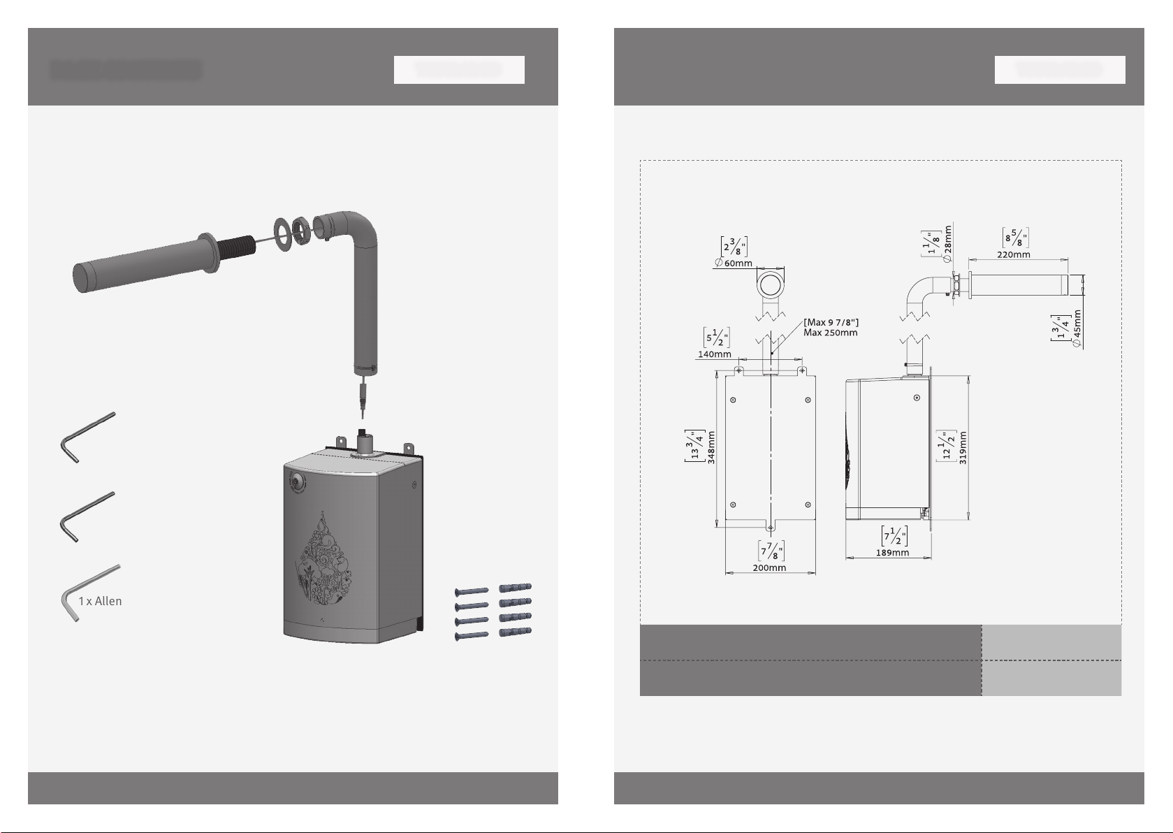
TUBULAR HD
PACK CONTENTS
x Hand dryer and attachments
x Hand dryer unit
TUBULAR HD
x Allen key mm
x Allen key .mm
x Allen key mm
x Screws & Ancors
Hose + clamps
6 7
TECHNICAL DATA
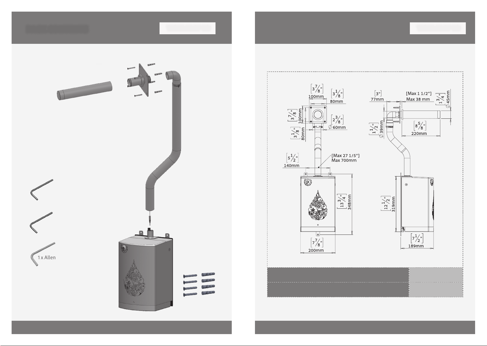
PACK CONTENTS TUBULAR DP HD
Tubular DP HD
Tubular DP HD AISI 316
x Hand dryer and attachments
x Hand dryer unit
TUBULAR DP HD
x Allen key mm
x Allen key .mm
x Allen key mm
x Screws & Ancors
x Screws & Ancors
Hose + clamps
This manual suits for next models
1
Table of contents
Popular Dryer manuals by other brands


ffuuss
ffuuss eos user manual

KitchenAid
KitchenAid 53-3498 installation instructions

Schulthess
Schulthess Spirit topLine TW 8340 operating instructions

Whirlpool
Whirlpool LGR4624BW0 parts list

World Dryer
World Dryer AirMax D M5-972A manual

Alliance Laundry Systems
Alliance Laundry Systems ADEE9BSS user guide


