Stern Engineering JUPITER 2030 Product manual

1
INSTALLATION AND MAINTENANCE GUIDE
ELECTRONIC FLUSH VALVE FOR URINAL

INDEX
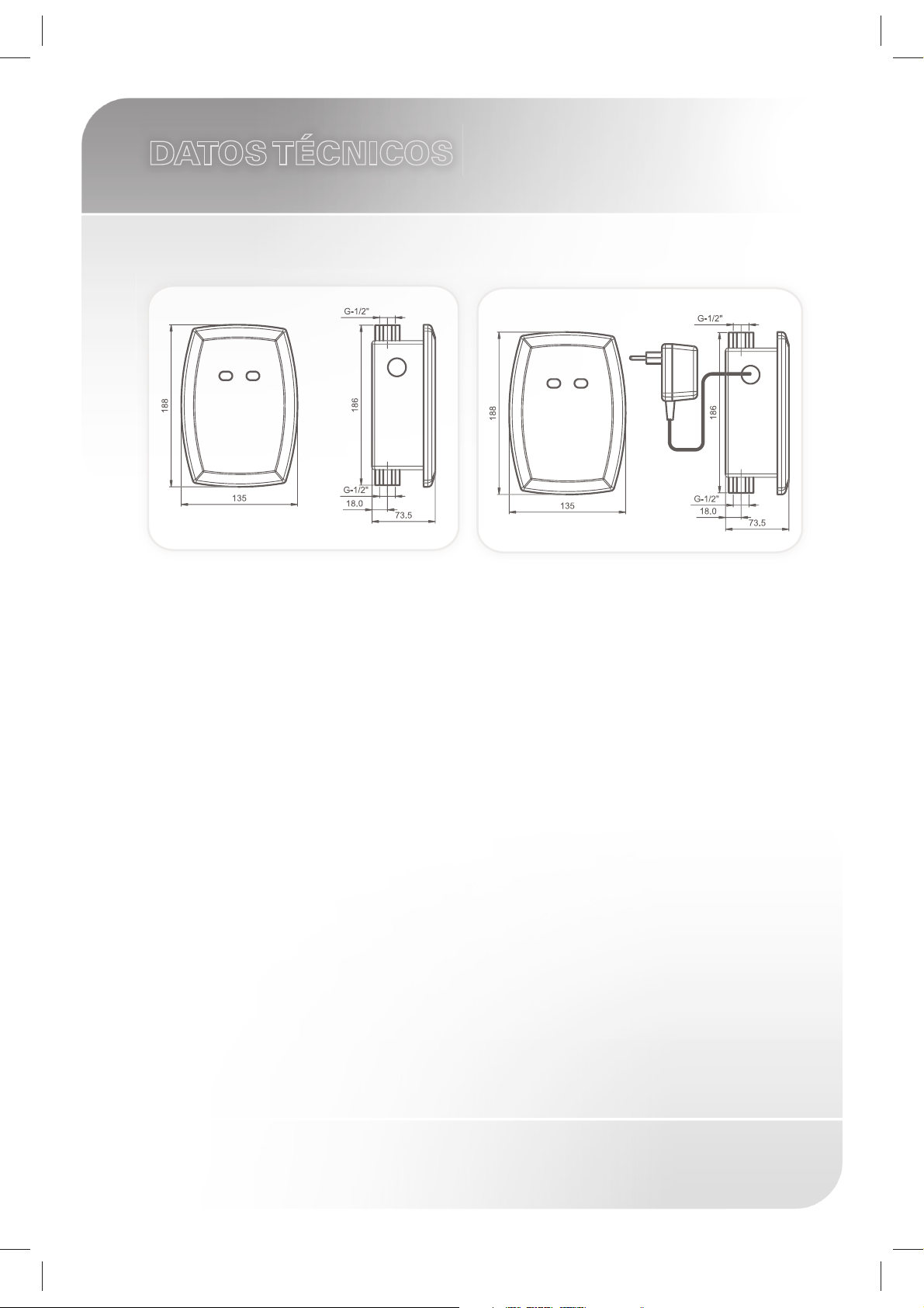
1 TECHNICAL DATA
2 PACK CONTENTS
3 PRE-INSTALLATION INFORMATION
4 INSTALLATION
5-8 SETTINGS ADJUSTMENT
9 BATTERY REPLACEMENT INSTRUCTIONS
10 MAINTENANCE
Filter cleaning instructions
Care and cleaning of chrome and special finishes
11 SPARE PARTS LIST
12 LIMITED WARRANTY
13 SERVICE CHECK LIST
1
DATOS TÉCNICOS
JUPITER 2030 JUPITER 2030 E
Power Supply: 9V battery or 9V transformer
Operating water pressure: 0.5-8.0 bar.
24 hours automatic flush when not used
to improved hygiene.
Sensor range: 600 mm. Factory set. Adjustable manually or with a
remote control.
Flushing Time: 6 secs. Factory set. Adjustable: 3 to 20 secs.
Prior use Flush Mode: Optional feature.

2
PACK CONTENTS
1 x M4x10 Screw
1 x Transformer
JUPITER 2030 E
Familiarize yourself with the part names and confirm that the parts are included.
1 x Plastic box with
concealed flush valve
1 x Temporary
protective panel
1 x Plastic seat for
the cover plate
1 x Wall cover plate with
the electronic unit and
battery box
4 x Screws
1 x Allen key

3
PRE–INSTALLATION INFO
Check contents
Separate all parts from packaging and check each part with the pack
contents section.
Make sure all parts are accounted for before discarding any packaging
material. If any parts are missing, do not attempt to install the electronic
flush valve until you obtain the missing parts.
Warnings
Do not install the system facing a mirror or any other electronic system
operated by an infra-red sensor.
To prevent reflection problems, it is recommended keep a minimum
distance of 1.50 meters between the flush valve and other objects.
Preparation for installation
Flush water supply lines thoroughly before installing the flush valve.
Do not allow dirt, Teflon tape or metal particles to enter the flush valve.
All plumbing is to be installed in accordance with applicable codes and
regulations.
Care and cleaning of chrome and special finishes
DO NOT use steel wool or cleansing agents containing alcohol, acid,
abrasives, or the like. Use of any prohibited cleaning or maintenance
products or substances could damage the surface of the flush valve.
For surface cleaning use ONLY soap and water, then wipe dry with
clean cloth or towel. When cleaning bathroom tile, the flush valve
should be protected from any splattering of harsh cleansers.
If system chemical disinfection is practiced, chlorine can be used (calculated
chlorine concentration of 50mg/l maximum in water per one hour dwell time)
at service interval frequency.
This manual suits for next models
1
Table of contents
Popular Toilet manuals by other brands


American Standard
American Standard CONCEPT Cube TF-2704 installation manual

BIOLAN
BIOLAN ECO Instructions for installation, use and maintenance

Thetford
Thetford C260 Series user manual

KELISS
KELISS T162A Series instruction manual

Silent Venus
Silent Venus SVP600 Installation & maintenance

Kohler
Kohler K-22241K Installation and care guide