manuals.online logo
Brands
  1. Home
  2. •
  3. Brands
  4. •
  5. steute
  6. •
  7. Switch
  8. •
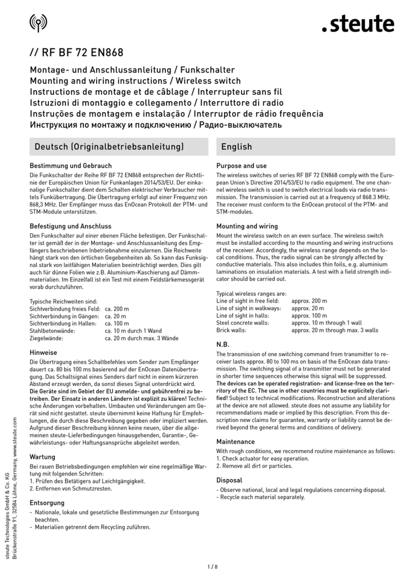
  9. steute RF 96 ST EN868 Programming manual

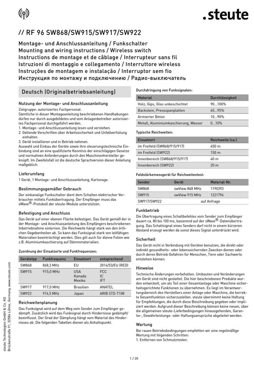
steute RF 96 ST EN868 Programming manual

steute Schaltgeräte GmbH & Co. KG
Brückenstraße 91, 32584 Löhne, Germany, www.steute.com
Deutsch
//
RF 96 ST EN868
Montage- und Anschlussanleitung / Funkschalter
Mounting and wiring instructions / Wireless switch
Instructions de montage et de câblage / Interrupteur de radio
Istruzioni di montaggio e collegamento / Interruttori di radio
Instruções de montagem e instalação / Interruptores de rádio frequência
Инструкция по монтажу и подключению / Переключатели c сигнальной технологией
Bestimmung und Gebrauch
Die Funkschalter der Reihe RF 96 ST EN868 entsprechen den Europä-
ischen Normen für Funkanlagen und Telekommunikationsendeinrich-
tungen 1999/5/EG. Der RF 96 ST besteht im wesentlichen aus drei Tei-
len. Der Energieversorgung mit der Lithiumbatterie, dem Funkteil mit
integriertem Interface für die externe Sensorik und dem Anschlussteil
für die externe Sensorik. Die Energieversorgung erfolgt mit einer nicht
wiederaufladbaren 3,6 V Lithium-Thionylchlorid-Batterie und einer
Nennkapazität von 8,5 Ah. Der Sensor/Schalter-Teil ist an dem M8-,
M12-Stecker herausgeführt. An diesem Stecker können die RF IS
M8/M12/M18- oder M30-Induktivsensoren oder andere mechanische
Schalter mit Goldkontakten angeschlossen werden. Hierfür kann die
als Zubehör erhältliche Anschlussleitung Mat.-Nr. 1189960 benutzt
werden. Bei den mechanischen Schaltern wird ein Schließer/Öffner-
Kontakt von Plus (Pin 1) zum Eingang (Pin 4) benötigt. Bei Überschrei-
ten des Schwellwertes wird eine Sendung des Funkteils ausgelöst.
Bei jeder Sendung wird auch der Spannungszustand der Batterie mit
übertragen. Die Übertragung erfolgt auf einer Frequenz von 868,3
MHz. Der Empfänger muss das EnOcean®Protokoll unterstützen.
Befestigung / Anschluss
Den Funkschalter auf einer ebenen Fläche befestigen. Der Funk-
schalter ist gemäß der in der Montage- und Anschlussanleitung des
Empfängers beschriebenen Inbetriebnahme einzulernen. Die Reich-
weite hängt stark von den örtlichen Gegebenheiten ab. So kann das
Funksignal stark von leitfähigen Materialien beeinträchtigt werden.
Dies gilt auch für dünne Folien wie z. B. Aluminium- Kaschierung auf
Dämmmaterialien. Typische Reichweiten sind:
Sichtverbindung freies Feld: ca. 300 m
Sichtverbindung in Gängen: ca. 30 m
Sichtverbindung in Hallen: ca. 100 m
Stahlbetonwände: ca. 10 m durch 1 Wand
Ziegelwände: ca. 20 m durch max. 3 Wände
Reichweitenplanung
Da es sich bei den Funksignalen um elektromagnetische Wellen han-
delt, wird das Signal auf dem Weg vom Sender zum Empfänger ge-
dämpft. D.h. sowohl die elektrische als auch die magnetische Feld-
stärke nimmt ab, und zwar umgekehrt proportional zum Quadrat des
Abstandes von Sender und Empfänger (E,H~1/r²) Neben dieser natürli-
chen Reichweiteneinschränkung kommen noch weitere Störfaktoren
hinzu: Metallische Teile, z. B. Armierungen in Wänden, Metallfol ien
von Wärmedämmungen oder metallbedampftes Wärmeschutzglas re-
flektieren elektromagnetische Wellen. Daher bildet sich dahinter ein
sogenannter Funkschatten. Zwar können Funkwellen Wände durch-
dringen, doch steigt dabei die Dämpfung noch mehr als bei Ausbrei-
tung im Freifeld. Durchdringung von Funksignalen:
Holz, Gips, Glas unbeschichtet 90...100%
Backstein, Pressspanplatten 65...95%
Armierter Beton 10...90%
Metall, Aluminiumkaschierung 0...10%
Sicherheit
Der Funkschalter darf nicht in Verbindung mit Geräten benutzt wer-
den, die direkt oder indirekt gesundheits- oder lebenssichernden Zwe-
cken dienen oder durch deren Betrieb Gefahren für Menschen, Tiere
oder Sachwerte entstehen können. Die Konformitätserklärung senden
wir Ihnen auf Wunsch gerne zu. Sie kann auch im Internet abgerufen
werden. Die hier beschriebenen Produkte wurden entwickelt, um als
Teil einer Gesamtanlage oder Maschine Funktionen zu übernehmen.
Es liegt im Verantwortungsbereich des Herstellers einer Anlage oder
Maschine, die korrekte Gesamtfunktion sicherzustellen.
Externe Sensoren/Schalter
Es sind unbedingt bei der Montage der Externen Sensoren/Schalter
deren Montageanleitungen zu beachten.
Hinweise
Die Verarbeitung eines Schaltbefehles vom Sender zum Empfänger
dauert ca. 80 bis 100 ms basierend auf der EnOcean Datenübertra-
gung. Das Schaltsignal eines Senders darf nicht in einem kürzeren
Abstand erzeugt werden da sonst dieses Signal unterdrückt wird.
Die Geräte sind im Gebiet der EU, der Schweiz und in Zypern anmel-
de- und gebührenfrei zu betreiben. Der Einsatz in anderen Ländern
ist explizit zu klären! Änderungen, die dem technischen Fortschritt
dienen, vorbehalten. Umbauten und Veränderungen am Schalter sind
nicht gestattet. steute übernimmt keine Haftung für Empfehlungen,
die durch diese Beschreibung gegeben oder impliziert werden. Auf-
grund dieser Beschreibung können keine neuen, über die allgemeinen
steute-Lieferbedingungen hinausgehenden, Garantie-Gewährleis-
tungs- oder Haftungsansprüche abgeleitet werden.
Wartung
Bei rauen Betriebsbedingungen empfehlen wir eine regelmäßige
Wartung mit folgenden Schritten:
1. Entfernen von Schmutzresten.
2. Bei Schaltern mit mechanischem Antrieb sind die beweglichen Ele-
mente gegeben falls nachzuschmieren und auf Leichtgängigkeit zu
prüfen.
Batterie
Die verbliebene Kapazität anhand der Batteriespannung zu bewerten
ist schwierig im Zweifelsfall und bei einer Batteriespannung ca. < 3,4 V
bei 20 °C ist von einer leeren Batterie auszugehen, für eine sichere
Funktion ist diese dann zu tauschen. Hierzu muss das Gehäuse mit
einem Torx 8 Schraubendreher an den 5 Deckelschrauben geöffnet
werden. Auf die Polung ist gemäß der Symbole im Gehäuse zu achten.
Es ist nur der vorgesehene oder komplementäre Batterietyp zu ver-
wenden. Je nachdem in welches Land das Gerät ausgeliefert wird, ist
eine AA Lithium-Batterie SL- 760/3,6V/2,2Ah in einem Batterieadapter
oder eine Lithium-Batterie SL-2770, 3,6 V, 8,5 Ah ohne Adapter bzw.
eine komplementäre enthalten. Ersatzteil bei steute: ET Lithium Bat-
terie SL-2770/S 3,6V/8,5Ah, Mat-Nr. 1202806, ET Lithium Batterie SL-
760 3,6V/2,2Ah, Mat-Nr. 1351045.
Entsorgung
Gebrauchte Elektro- und Elektronikgeräte dürfen gemäß europäischer
Vorgaben nicht mehr zum unsortierten Abfall gegeben werden. Das
Symbol der Abfalltonne auf Rädern weist auf die Notwendigkeit der
steute Schaltgeräte GmbH & Co. KG
Brückenstraße 91, 32584 Löhne, Germany, www.steute.com
Deutsch
//
RF 96 ST EN868
Montage- und Anschlussanleitung / Funkschalter
Mounting and wiring instructions / Wireless switch
Instructions de montage et de câblage / Interrupteur de radio
Istruzioni di montaggio e collegamento / Interruttori di radio
Instruções de montagem e instalação / Interruptores de rádio frequência
Инструкция по монтажу и подключению / Переключатели c сигнальной технологией
getrennten Sammlung hin. Helfen auch Sie mit beim Umweltschutz
und sorgen dafür, dieses Gerät, wenn Sie es nicht mehr nutzen, in die
hierfür vorgesehenen Systeme der Getrenntsammlung zu geben.
Ruchtlinie 2002/96/EG des europäischen Parlaments und des Rates
vom 27. Januar 2003 über Elektro- und Elektronik-Altgeräte. Weitere
Informationen zu Entsorgungsmöglichkeiten erhalten Sie bei Ihrem
zuständigen Entsorgungsunternehmen. Leere Batterien sofort entfer-
nen und umweltgerecht entsorgen. Batterien nicht in den Hausmüll
werfen. Auskunft über umweltgerechte Entsorgung gibt die kommu-
nale Behörde. Gemäß gesetzlichen Vorgaben ist der Endverbraucher
zur Rückgabe gebrauchter Batterien verpflichtet.
Statussignal
Ein Statussignal ist nicht vorgesehen.
ESD
Bei allen arbeiten die das Öffnen des Gerätes erforderlich machen ist
auf ausreichenden ESD-Schutz zu achten.
English
Destination and use
The wireless switches of series RF 96 ST EN868 comply with the Eu-
ropean standards on radio equipment and telecommunications termi-
nal equipment 1999/5/EC. The RF 96 ST consists of three parts. The
energy supply with lithium battery, the wireless part with integrated
interface for the external sensors and the connection part for the ex-
ternal sensors. The ernergy supply is carried out by a not rechargeable
3.6 V lithium-thionylchloride battery and a nominal capacity of 8.5 Ah.
The sensor/switch part is evident at the M12 plug-in connector. At this
plug-in connector the inductive sensors RF IS M8/M12/M18- or M30
or other mechanical switches with gold-plated contacts can be con-
nected. Therefor the connecting cable material number 1189960 can
be used that is available as accessory. The mechanical switches must
be equipped with a NO/NC contact. It must be connected to plus (pin 1)
and to the entry (pin 4). When exceeding the threshold a wireless sig-
nal ot the wireless part is transmitted. The battery status is transmit-
ted with every signal transmission. The transmission is carried out at a
frequency of 868.3 MHz. The receiver must conform to the EnOcean®
protocol.
Mounting / Wiring
The wireless switch should be mounted on an even surface. The sens-
ing range accordingly depends on the local conditions. Thus the radio
signal can be strongly affected by conductive materials. This also in-
cludes thin foils, e.g. aluminium laminations on insulation materials.
Typical sensing ranges are:
Sight connection outside: approx. 300 m
Sight connection in walkways: approx. 30 m
Sight connection in halls: approx. 100 m
Steel concrete walls: approx. 10 m through 1 wall
Brick walls: approx. 20 m through max. 3 walls
Design of sensing range
Because radio signals are electromagnetic waves the signal is attenu-
ated on its way from the transmitter to the receiver. This means the
electrical as well as the magnetic field strengths decrease and in fact
inversely proportional to the squared distance of transmitter and re-
ceiver (E,H~1/r²). In addition to this natural restriction of the sensing
range further interference factors occur: Metal parts, e. g. armours in
walls, metal foils of thermal insulations or vapour deposited metal
layer heat protection glass reflect electromagnetic waves. Therefore a
socalled deadspot can be found behind them. Indeed radio waves are
able to penetrate walls but the attenuation increases even more than
in the free field. Penetration of radio waves:
wood, gypsum, glas uncoated 90...100%
brick stone, press boards 65...95%
armoured concrete 10...90%
metal, aluminium lamination 0...10%
Notices
The transmission of one switching command from transmitter to re-
ceiver lasts approx. 80 to 100 ms on basis of the EnOcean data trans-
mission. The switching signal of a transmitter must not be generated
in shorter time sequences otherwise this signal will be suppressed.
The devices can be operated registration- and license-free on the
territory of the EC, Switzerland and Cyprus. The use in other coun-
tries must be explicitely clarified! Subject to technical modifications.
Reconstruction and alterations at the switch are not allowed. Moreover
steute does not assume any liability for recommendations made or
implied by this description. From this description new claims for guar-
antee, warranty or liability cannot be derived beyond the general terms
and conditions of delivery.
Safety
The wireless switch must not be used in connection with devices that
directly or indirectly serve health- or life-saving purposes or which
may when operated endanger human beings, animals or assets. The
declaration of conformity is available on request or can be downloaded
from our website. The products described were developed to function
as part of an overall plant or machine. The functioning of the overall
plant or machine is the responsibility of the manufacturer.
External sensors / switches
When mounting external sensors/switches, the mounting instructions
must be observed at all times.
Maintenance
With rough conditions, we recommend routine maintenance as follows:
1. Remove all dirt or particles.
2. Regarding switches with a mechanical drive, movable parts might
require further greasing and must be checked for smooth running.
Battery
The remaining capacity of a battery is hard to evaluate, but an empty
battery can be assumed in case of doubt and with a battery voltage <
3.4 V at 20 °C. The battery should be replaced to ensure reliable func-
tioning. To do this, open the enclosure by removing the 5 cover screws
using a Torx 8 screwdriver. Check that polarity matches the symbols
inside the enclosure. Use only the designated or a complementary bat-
steute Schaltgeräte GmbH & Co. KG
Brückenstraße 91, 32584 Löhne, Germany, www.steute.com
English
//
RF 96 ST EN868
Montage- und Anschlussanleitung / Funkschalter
Mounting and wiring instructions / Wireless switch
Instructions de montage et de câblage / Interrupteur de radio
Istruzioni di montaggio e collegamento / Interruttori di radio
Instruções de montagem e instalação / Interruptores de rádio frequência
Инструкция по монтажу и подключению / Переключатели c сигнальной технологией
tery type. Depending on the country of delivery, the device will be
equipped with an AA lithium battery SL- 760/ 3.6V/ 2.2Ah in a battery
adapter; or a lithium battery SL-2770/ 3.6 V/ 8.5 Ah without an adapter;
or a complementary battery. Spare parts available at steute: ET lithium
battery SL-2770/ S 3.6V/ 8.5Ah, material number 1202806; ET lithium
battery SL-760/ 3.6V/ 2.2Ah, material number 1351045.
Disposal
In accordance with the European guidelines, electrical and electronic
devices may not be disposed of with unsorted waste. The wheelie bin
symbol indicates the necessity for separate waste disposal. Help us to
save the environment by taking care to dispose of the device correctly,
in the separate collection, when it is no longer required. See Directive
2002/96/EC of the European parliament and council from January
27th, 2003 about used electrical and electronic devices. You can obtain
further information about disposal options from your waste collector.
Empty batteries must be removed immediately and disposed of in an
environmentally friendly manner, not in the unsorted household waste.
Information on environmentally compatible disposal of batteries is
available from your municipal authority. According to the legal stipula-
tions, end users are obliged to return used batteries to a designated
collection point.
Status signal
A status signal is not designed.
ESD
With all operations that require opening of the enclosure, sufficient
ESD protection must be guaranteed.
Français
Destination et emploi
Les interrupteurs de position RF 96 ST EN868 répondent aux exi-
gences des normes européennes relatives aux équipements radio et
de télécommunication 1995/5/CE. Le RF 96 ST se compose essentiel-
lement de trois parties. L'alimentation en énergie avec un accumula-
teur au lithium, l'unité de radio avec interface intégrée pour la tech-
nique sensorielle externe et l’élément connecteur pour la technique
sensorielle externe. L'alimentation en énergie est fournie par une pile
de 3,6 V Lithium Chlorure de Thionyl non rechargeable et une capa-
cité nominale de 8,5 Ah. La partie capteur/commutateur fait partie
intégrante du connecteur M12. Les capteurs inductifs RF IS M8/M12/
M18- ou M30 ou autres commutateurs mécaniques avec des contacts
dorés peuvent y être connectés. Pour cela, le câble de connexion Mat.
N°1189960, livrable en option, peut être utilisé. Pour les interrupteurs
mécaniques, un contact NO / NF de Plus (broche 1) à l'entrée (broche
4) est nécessaire. Lorsque la valeur seuil est dépassée, une émission
de l’unité de radio est déclenchée. Avec chaque émission, l’état de ten-
sion de la batterie est également transmis. La transmission radio a
lieu sur une fréquence fixe de 868,3 MHz. Le récepteur de commande
utilise le protocole de communication EnOcean®.
Montage / Raccordement
L'interrupteur de position est à fixer exclusivement sur des surfaces
planes. La distance de détection est grandement dépendante des
conditions locales. Ainsi le signal radio est fortement influé par les
matériaux conducteurs. Ceci concerne également les tôles fines,
telles les feuilles d‘aluminium co-laminées des matériaux isolants.
Quelques portées typiques:
En vision directe champ libre: environ 300m
En vision directe dans un couloir: environ 30m
En vision directe en atelier: environ 100m
A travers un mur en béton armé: environ 10m
A travers des cloisons brique/plâtre: environ 20m (3 cloisons maxi)
Planification du rayon d’action
Comme il s’agit dans les signaux radioélectriques d’ondes électroma-
gnétiques, le signal s’affaiblit en allant de l’émetteur au récepteur.
Cela veut dire que l’intensité du champ électrique et magnétique dimi-
nue, proportionnellement inverse au carré de la distance entre émet-
teur et récepteur (E,H~1/r²). Outre cette limite de rayon d’action natu-
relle s’ajoutent des éléments perturbateurs supplémentaires:
Des parties métalliques, par exemple, des armatures dans les murs,
des feuilles métalliques contenues dans l’isolation thermique ou du
verre calorifuge métallisé au vide, reflètent les ondes électromagné-
tiques. En conséquence, il se produit une soi-disant zone morte dans
les radio-émissions. Certes les ondes radioélectriques peuvent traver-
ser des murs, mais l’affaiblissement augmente encore plus que lors
de la propagation en espace libre. Pénétration des signaux radio:
bois, plâtre, verre non enduit 90...100%
brique, panneaux stratifiés 65...95%
béton armé 10...90%
métal, placage aluminium 0...10%
Remarques
La durée de transmission d’un émetteur vers le récepteur est d’environ
80 à 100msec, sur la base de la technologie radio EnOcean. Un nou-
veau signal ne doit pas être généré dans un laps de temps inférieur,
sans quoi il risque de ne pas être pris en compte. Ces appareils sont
utilisables sans licence et sans enregistrement préalable, dans les
pays de l’UE, en Suisse et Chypre.
L'application dans autres pays in
doit être clarifier de façon explicite!
Sous réserve de modifications
techniques. Toute modification ou transformation de l’interrupteur est
interdite. Les caractéristiques et recommandations figurant dans ce
document sont données exclusivement à titre d’information et sans
engagement contractuel de la part de steute.
Sécurité
L’interrupteur sans fil ne doit pas être utilisé avec des dispositifs qui
servent, directement ou indirectement, à la santé ou à la sécurité, ou
qui peuvent présenter un danger pour les personnes, les animaux ou
les biens matériels lors de leurs utilisations. La déclaration de confor-
mité peut vous être envoyée sur simple demande. Elle est également
disponible sur internet. Les produits décrits ici ont été développés
pour assumer des fonctions en tant que partie d’une d’installation
complète ou d’une machine. Il en va de la responsabilité du fabricant
de l’installation ou de la machine d’assurer le fonctionnement correct
de l’ensemble.
steute Schaltgeräte GmbH & Co. KG
Brückenstraße 91, 32584 Löhne, Germany, www.steute.com
//
RF 96 ST EN868
Montage- und Anschlussanleitung / Funkschalter
Mounting and wiring instructions / Wireless switch
Instructions de montage et de câblage / Interrupteur de radio
Istruzioni di montaggio e collegamento / Interruttori di radio
Instruções de montagem e instalação / Interruptores de rádio frequência
Инструкция по монтажу и подключению / Переключатели c сигнальной технологией
Français
Capteurs / interrupteurs externes
Il faut absolument respecter les instructions de montage des capteurs
/ interrupteurs externes lors de leur installation.
Entretien
En cas de fonctionnement dans un environnement difficile, il est
recommandé d'effectuer un entretien régulier qui consiste à:
1. Eliminer les salissures.
2. Pour les interrupteurs à entraînement mécanique, les éléments
mobiles doivent être éventuellement lubrifiés et leur souplesse
d’utilisation est à contrôler.
Pile
En cas de doute il est difficile d’évaluer la capacité restante par la ten-
sion de la pile. Avec une tension d’environ < 3,4 V à 20 °C, il faut consi-
dérer la pile comme déchargée et donc la remplacer pour assurer sa
fonction fiable. Pour cela, dévisser les 5 vis du couvercle du boîtier
avec un tournevis Torx 8. Veiller à la polarité conformément aux sym-
boles dans le boîtier. Il ne doit être utilisé que le type de pile prévu ou
complémentaire. Selon le pays dans lequel l'appareil sera livré, une
pile lithium AA SL- 760 / 3.6 V / 2.2 Ah dans un adaptateur pile, ou une
pile lithium SL-2770 / 3,6 V / 8,5 Ah sans adaptateur ou bien une pile
complémentaire est inclue. Pièce de rechange steute: ET pile lithium
SL-2770/S / 3.6 V / 8,5 Ah, code-article 1202806, ET pile lithium SL-760
/ 3,6 V / 2,2 Ah, code-article 1351045.
Elimination des déchets
Selon les directives européennes, les appareils électriques et électro-
niques usagés ne doivent plus être jetés sans être triés. Le symbole de
la poubelle sur roues signale la nécessité de la collecte sélective.
Aidez vous aussi à préserver l’environnement et, si vous ne l'utilisez
plus, veillez à ce que cet appareil rejoigne le système de collecte sé-
lective prévu à cet égard. Directive 2002/96/EG du Parlement européen
et du Conseil du 27 janvier 2003 relative aux déchets d’équipement
électriques et électroniques. Pour de plus amples informations
concernant les méthodes d’élimination appropriées, veuillez contacter
votre entreprise de collecte des déchets compétente. Les piles vides
sont à enlever immédiatement et à éliminer en respectant l’environne-
ment. Ne pas jeter les piles dans les ordures ménagères. L’adminis-
tration communale informe sur l’élimination écologique des déchets.
Selon les directives légales, l’utilisateur final est obligé de rendre les
piles usagées.
Signal d’état
Un signal d'état n'est pas prévu.
ESD
Il faut veiller à une protection suffisante contre les décharges électros-
tatiques lors de tous travaux qui exigent l’ouverture de l’appareil.
Italiano
Destinazione ed uso
I interruttori di radio della serie RF 96 ST EN868 adempiono alle
normative Europee per per impianti di radiotrasmissione e apparec-
chiature terminali di telecomunicazione 1999/5/EG. Il dispositivo RF
96 ST consiste essenzialmente di tre parti. L’alimentatore con batteria
al litio, l’unità radio con interfaccia integrata per i sensori esterni e il
connettore per i sensori esterni. Viene alimentato da una batteria al
litio-cloruro di tionile non ricaricabile da 3,6 V ed una capacità nomina-
le di 8,5 Ah. L’unità del sensore/interruttore è connesso al connettore
M12. A questo connettore possono essere collegati i sensori di prossi-
mità induttivi RF IS M8/M12/M18 o M30, oppure altri interruttori mec-
canici con contatti dorati. A questo scopo può essere utilizzato il cavo
di collegamento, disponibile come accessorio con il codice1189960.
Con gli interruttori meccanici, è necessario un contatto NC/NA dall’in-
gresso Pin 1 all’ingresso Pin 4. Quando viene azionato, l’unità radio
genera un messaggio, trasmettendo anche lo stato di carica della bat-
teria. La trasmissione avviene ad una frequenza di 868,3 MHz. I ricevi-
tore devono supportare il protocollo EnOcean®dei moduli PTM e STM.
Montaggio e collegamenti
Il finecorsa di posizione così dovrebbero essere montati su una super-
ficie uniforme. Il campo d’azione dipende molto dalle caratteristiche del
luogo d’impiego. Infatti il segnale radio può venire peggiorato da mate-
riali conduttibili. Questo vale anche per sottili fogli come i rivestimenti
d’alluminio su materiali isolanti. Le distanze tipiche sono:
Collegamento a vista su campo aperto: ca. 300 m
Collegamento a vista in corridoi: ca. 30 m
Collegamento a vista in capannoni: ca. 100 m
Muri di cemento armato: ca. 10 m attraverso 1 muro
Muri di mattoni: ca. 20 m attraverso max. 3 muri
Progettazione del raggio d'azione
Poiché nel caso dei segnali radio si tratta di onde elettromagnetiche, il
segnale viene attenuato lungo il percorso che va dal trasmettitore al
ricevitore. Ciò significa che si riduce sia l'intensità di campo elettrica
che quella magnetica, in maniera inversamente proporzionale al qua-
drato della distanza da trasmettitore a ricevitore (E,H~1/r²). A parte
questa limitazione naturale del raggio d'azione esistono ulteriori fatto
ri di disturbo: parti metalliche, ad es. armature sulle pareti, fogli me-
tallici di isolamenti termici o vetro di sicurezza termico metallizzato a
vapore riflettono onde elettromagnetiche. Dietro questi ostacoli si
forma dunque una cosiddetta zona d'ombra. Per quanto le onde radio
siano in grado di attraversare le pareti, l'attenuazione è superiore ri-
spetto alla propagazione in campo aperto. Penetrazione di segnali
radio:
Legno, gesso, vetro non rivestito 90...100%
Laterizio, pannello di trucciolato 65...95%
Cemento armato 10...90%
Metallo, rivestimento in alluminio 0...10%
Indicazioni
La trasmissione di un comando di commutazione dal trasmettitore al
ricevitore impiega ca. 80 – 100 ms in base alla trasmissione dati secondo
EnOcean. Il segnale di commutazione di un trasmettitore non deve essere
steute Schaltgeräte GmbH & Co. KG
Brückenstraße 91, 32584 Löhne, Germany, www.steute.com
//
RF 96 ST EN868
Montage- und Anschlussanleitung / Funkschalter
Mounting and wiring instructions / Wireless switch
Instructions de montage et de câblage / Interrupteur de radio
Istruzioni di montaggio e collegamento / Interruttori di radio
Instruções de montagem e instalação / Interruptores de rádio frequência
Инструкция по монтажу и подключению / Переключатели c сигнальной технологией
Italiano
generato ad una distanza inferiore altrimenti il segnale verrà soppresso.
L’utilizzo di questi apparecchi è esente da tasse per la licenza d’uso
nell’area UE, in Svizzera e Cipro. L’impiego in altre nazioni deve essere
chiarito in modo esplicito! Soggetta a modifiche tecniche. Ricostruzioni
e modifiche dell’interruttore non sono permesse. steute non si assume
alcuna responsabilità per suggerimenti impliciti od espliciti forniti da
questa descrizione. Da questa descrizione nuovi reclami di assicura-
zione, garanzia o responsabilità non possono essere formulati oltre le
condizioni generali e modalità di consegna.
Sicurezza
L’interruttore a pedale wireless non deve essere utilizzato insieme a
dispositivi che direttamente o indirettamente servono a scopi di salute
o salva-vita, oppure che con il loro funzionamento possano rappresen-
tare un pericolo per persone, animali o cose. Su richiesta, vi invieremo
la dichiarazione di conformità. E’ possibile richiederla anche tramite il
sito internet. I prodotti qui descritti sono stati sviluppati per adempiere
a funzioni come parte di una macchina o di un impianto completo. E’
responsabilità del costruttore della macchina o dell’impianto assicura-
re il corretto funzionamento complessivo.
Sensori / interruttori esterni
Per il montaggio di sensori/interruttori esterni, devono essere osser-
vate le relative istruzioni di montaggio.
Manutenzione
In condizioni di impiego in ambienti gravosi si consiglia una manuten-
zione periodica come segue:
1. Rimuovere tutti i residui di sporco.
2. Negli interruttori con azionamento meccanico, gli elementi mobili
devono essere lubrificati e si deve verificare che possano muoversi
con facilità.
Batteria
E‘ difficile stimare la capacità residua di una batteria. In caso di dubbi
e con una tensione < 3,4 V a 20 °C, si può assumere che la batteria
sia scarica. Per un funzionamento sicuro, la batteria deve essere
sostituita. A questo scopo è necessario aprire l’alloggiamento utiliz-
zando un cacciavite Torx 8 per le 5 viti del coperchio. Rispettare la
polarità secondo i simboli riportati sul coperchio. Utilizzare soltanto il
tipo di batteria previsto o un complementare. A seconda del Paese in
cui viene fornito l’apparecchio, è inclusa una batteria al litio AA SL-
760/3,6V/2,2Ah in un adattatore per batteria, oppure una batteria al
litio SL-2770, 3,6 V, 8,5 Ah senza adattatore, oppure una complemen-
tare. Ricambi steute: ET Lithium Battery SL-2770/S 3,6V/8,5Ah, Codice
materiale 1202806, ET Lithium Battery SL-760 3,6V/2,2Ah, Codice
materiale 1351045.
Smaltimento
Secondo le direttive europee, le apparecchiature elettriche ed elettro-
niche usate non devono più essere gettate nei rifiuti indifferenziati. Il
simbolo del bidone dei rifiuti su ruote indica la necessità di raccolta
differenziata. Aiutate anche voi a proteggere l’ambiente e abbiate cura
che questo apparecchio, quando non sarà più utilizzato, venga getta-
Português
Definições e uso
Os interruptores de rádio frequência da linha RF 96 ST EN868 aten-
dem plenamente as exigências nos termos das normas européias para
equipamentos de rádio e telecomunicações 1999/5/EC. O RF 96 ST
constitui-se basicamente de três partes. A bateria de lítio como fonte
de energia, o transmissor com interface integrada para os sensores
externos e o conector para o acoplamento de sensores externos. O
fornecimento da energia ocorre por meio de uma bateria de íon-lí-
tio não recarregável de 3,6V e uma capacidade de 8,5 Ah. A parte do
sensor faz a conexão via o conector M12. Neste conector podem-se
conectar os módulos RF IS M8/M12/M18 ou sensores indutivos M30 ou
outras chaves mecânicas com contatos de ouro. Para isso pode-se uti-
lizar o cabo de conexão com número de produto 1189960 vendido como
acessório. Para chaves mecânicas é necessário o uso de um bloco de
contato NA/NF do positivo (pino 1) para a saída (pino 4). Ao exceder o
nível de sinal uma transmissão é realizada. A cada transmissão tam-
bém é transmitido o nível de tensão da bateria. A transmissão é reliza-
da numa Frequência de 868,3 MHz. O receptor deverá dar suporte ao
protocolo EnOcean®.
Montagem/Conexão
Fixar os fins de curso sobre uma superfície plana. A programação do
interruptor atuado por rádio Frequência deverá ser realizada de acor-
do com o que consta nas instruções de montagem, ligação e colocação
em funcionamento do receptor. Assim o sinal da rádio Frequência pode
ser comprometido significativamente por materiais de boa conduti-
bilidade. Esta assertiva també é aplicável para os casos de forrações
acústicas, como em revestimentos que se utilizem de laminados de
aluminio. Distâncias de alcance típico são:
Comunicação visual, em área livre: aprox. 300 m
Comunicação visual, em corredores: aprox. 30 m
Comunicação visual, em pavilhões / galpões: aprox. 100 m
Paredes de aço e concreto: aprox. 10 m através de 1 parede
Paredes de tijolo: aprox. 20 m através de 3 paredes
to all’interno del sistema di raccolta differenziata previsto. Direttiva
2002/96/EG del Parlamento Europeo e Consiglio del 27 gennaio 2003
sulle apparecchiature elettriche ed elettroniche usate. Per ulteriori
informazioni sulle opzioni di smaltimento è possibile rivolgersi alle
aziende di smaltimento competenti. Rimuovere immediatamente le
batterie scariche ed eliminarle nel rispetto dell‘ambiente. E’ possibile
reperire informazioni riguardo lo smaltimento nel rispetto dell’am-
biente presso le autorità locali. Secondo la normativa, l’utilizzatore
finale è tenuto a restituire le batterie usate.
Segnale di stato
Non è previsto un segnale di stato.
ESD
Per tutte le operazioni che richiedono l’apertura dell’apparecchio, as-
sicurare un’adeguata protezione ESD.
steute Schaltgeräte GmbH & Co. KG
Brückenstraße 91, 32584 Löhne, Germany, www.steute.com
//
RF 96 ST EN868
Montage- und Anschlussanleitung / Funkschalter
Mounting and wiring instructions / Wireless switch
Instructions de montage et de câblage / Interrupteur de radio
Istruzioni di montaggio e collegamento / Interruttori di radio
Instruções de montagem e instalação / Interruptores de rádio frequência
Инструкция по монтажу и подключению / Переключатели c сигнальной технологией
Português
Definindo o alcance
Os sinais de radio são basicamente ondas eletromagnéticas o sinal é
atenuado no caminho entre o transmissor e o receptor. Isto significa
que a intensidade dos campos elétrico e magnético é reduzida de
forma inversamente proporcional ao quadrado da distância do trans-
missor ao receptor (E,H~1/r²). Adicionalmente a esta restrição natural
do alcance outros fatores de interferência acontecem. Partes metáli-
cas, por exemplo, vergalhões nas paredes, folhas de alumínio ou vi-
dros com camadas de metal depositadas por vaporização usados em
isolamento térmico podem refletir ondas magnéticas. Desta forma um
“ponto cego” pode ser localizado atrás destes elementos. Na realidade
ondas de rádio podem atravessar paredes, porém a atenuação é maior
do que em através do ar. Penetração das ondas de rádio:
Madeira, gesso, vidro sem tratamento 90... 100%
Tijolo, compensado 65... 95%
Concreto armado 10... 90%
Metais, lâminas de alumínio 0... 10%
Comunicação visual, em área livre aprox. 450 m
Segurança
A chave wireless não deve ser utilizada em conexão com dispositivos
que podem servir direta ou indiretamente para propósitos na área da
saúde ou socorro de vidas ou provocar riscos de operação para seres
humanos, animais ou bens. A declaração de conformidade está dispo-
nível sob solicitação ou pode ser baixada em nosso site. Os produtos
descritos foram desenvolvidos de forma a assumir as funções de se-
gurança, como parte de uma instalação ou equipamento. A responsa-
bilidade tomada pelo fabricante de uma máquina ou instalação implica
a garantir a total e correta função.
Sensore / chaves externas
Ao montar os sensores/chaves externas devem ser observadas as ins-
truções de montagem.
Observações
A transmissão do comando de comutação, do transmissor ao receptor,
tem uma duração de aproximadamente 80 a 100 ms, isto baseado na
transmissão de dados no protocolo EnOcean. O sinal de comutação do
transmissor não pode ser gerado em intervalo menor, uma vez que
este será suprimido. A instalação destes equipamentos está libe-
rada, isto é, sem obrigatoriedade de registro e pagamento de taxas
de licença, nas áreas da EU = Comunidade Européia, Suíça e Chipre.
A aplicação em outros países deverá ser verificada explicitamente!
Estão reservados todos os direitos para executar alterações em prol
do desenvolvimento. Modificações e alterações no interruptor não são
permitidas. A steute não assume qualquer responsabilidade por reco-
mendações que possam vir a ser deduzidas, ou, implicitadas ao texto
constante nesta descrição. Esta descrição não permite que se façam
quaisquer tipos de exigências adicionais que possam vir a ultrapassar
ao estabelecido nas condições gerais de fornecimento, garantias, res-
ponsabilidades e/ou penalidades.
Manutenção
Nos casos em que os equipamentos estiverem instalados em condi-
ções ambientes adversas é recomendado que seja realizada a conser-
vação obedecendo os passos seguintes:
1. Eliminar restos de sujeira.
2. Nas chaves com acionamento mecânico as, partes móveis devem
ser lubrificadas se necessário e o movimento deve ser verificado.
Bateria
A capacidade remanescente de uma bateria é de difícil avalição. Em
caso de dúvida e com uma tensão de bateria <3,4 V a 20 ° C pode se
assumir que a bateria esteja vazia. Para uma função segura a bateria
deve ser substituída. Neste caso o invólucro deve ser aberto por um
chave Torx 8 removendo os 5 parafusos da tampa. Observar a polari-
dade de acordo com os símbolos dentro do invólucro. Somente bate-
riais originais ou bateria similar deve ser utilizada. Dependendo do
país para onde o dispositivo é fornecido desde então é equipado com
uma bateria de lítio SL- AA 760 / 3,6V / 2,2Ah em um adaptador de ba-
teria ou uma bateria de lítio SL-2770, 3.6 V, 8.5 Ah, sem adaptador ou
uma bateria complementar é fornecida. Peça de reposição na steute:
ET lítio SL-2770 / S 3,6V / 8,5Ah, número de material 1.202.806, ET lítio
SL-760 3,6V / 2,2Ah, número de material 1.351.045.
Descarte
De acordo com as orientações europeias, aparelhos elétricos e eletrô-
nicos usados devem ser descartados separadamente. O símbolo de li-
xeiras indica a necessidade de coleta seletiva de resíduos. Ajude-nos a
salvar o nosso meio ambiente, cuidando do descarte correto quando o
dispositivo não for mais necessário. Existem sistemas destinados ao
descarte seletivo (Diretiva 2002/96 / CE do Parlamento Europeu e do
Conselho de 27 de Janeiro de 2003 sobre aparelhos elétricos e eletró-
nicos descartados). Maiores informações sobre opções de descarte
você pode receber da Área de Gestão de Resíduos de sua empresa.
Baterias vazias devem ser removidas imediatamente e eliminadas
ecologicamente. As baterias não devem ser descartadas no lixo do-
méstico. Informações sobre o descarte ambientalmente correto são
fornecidas pelo município. De acordo com os requisitos legais, o usuá-
rio final é obrigado a devolver as baterias usadas.
Sinal de status
Um sinal de status não é fornecido.
ESD
Como todas as operações que requerem uma abertura do invólucro, a
proteção ESD deve ser assegurada.
steute Schaltgeräte GmbH & Co. KG
Brückenstraße 91, 32584 Löhne, Germany, www.steute.com
//
RF 96 ST EN868
Montage- und Anschlussanleitung / Funkschalter
Mounting and wiring instructions / Wireless switch
Instructions de montage et de câblage / Interrupteur de radio
Istruzioni di montaggio e collegamento / Interruttori di radio
Instruções de montagem e instalação / Interruptores de rádio frequência
Инструкция по монтажу и подключению / Переключатели c сигнальной технологией
Русский
Предназначение и использование
Pадиовыключатели серий RF 96 ST EN868 подчинены Европейским
Стандартам для радиооборудования и телекоммуни-кационного
оборудования 1999/5/ЕС. RF 96 ST состоит в основном из трех
частей. Из блока энергообеспечения с литиевой батарей, радио-
блока со встроенным интерфейсом для внешних датчиков и блока
подключения внешних датчиков. Энергообеспечение осуществля-
ется не заряжаемой литиево-тионилхлоридной батареей на 3,6 V
и номинальной емкостью 8,5 Ah. Блок датчиков и выключателей
выведен на M12-штекер. К этому штекеру могут быть подключены
RF IS M8/M12/M18- или M30 индуктивные датчики или другие ме-
ханические выключатели с золотыми контактами. Для этого может
применяться поставляемый в качестве принадлежностей кабель
подключения Mat.-Nr. 1189960. У механических выключателей
требуется один НЗ/НР-контакт с плюса (пин 1) ко входу (пин 4). При
превышении порогового значения запускается передача радио
блока. При каждой передаче передается и состояние напряжения
батареи. Передача сигнала происходит на частоте 868,3 мГц. При-
емник должен поддерживать протокол EnOcean®.
Монтаж / Подключение
Позиционные переключатели могут быть смонтированы на любых
подходящих поверхностях. Выключатель необходимо настроить в
соответствии с условиями ввода в эксплуатацию, описанными в Ин-
струкции по монтажу и подключению. Дальность передачи сильно
зависит от местных условий. Так например токопроводящие матери-
алы могут ухудшать радиосигнал. Это касается также тонкой фольги,
как например алюминиевое покрытие изоляционных материалов.
Типичные значения дальности передачи:
в пределах прямой видимости в чистом поле: прибл. 300 м
в пределах прямой видимости в проходах: прибл. 30 м
в пределах прямой видимости в помещениях: прибл. 100 м
железобетонные стены: прибл. 10 м через 1 стену
кирпичные стены: прибл. 20 м через максимум 3 стены
Планирование дальности передачи
Так как при передаче радиосигналов речь идет об электромагнит-
ных волнах, сигнал на пути от передатчика к приемнику затухает.
Это означает что сила поля как и электрического так и магнитного
снижается, а именно обратно пропорционально квадрату расстоя-
ния от передатчика к приемнику (E,H~1/r²) К этому естественному
ограничению дальности передачи добавляются и другие мешаю-
щие факторы: металлические части, например, арматура в стенах,
металлическая фольга утеплителей или металлическое напыление
на теплозащитном стекле отражают электромагнитные волны. Поэ-
тому за ними образуется зона отсутствия приема. И хотя радиовол-
ны могут проникать через стены, затухание увеличивается еще
сильнее, чем при распространении в свободном пространстве. Про-
никновение радиосигналов:
Дерево, гипс, стекло без покрытия 90...100%
Кирпич, ДСП 65...95%
Армированный бетон 10...90%
Металл, каширование алюминием 0...10%
Безопасность
Не допустимо использовать радио-выключатель в сочетании с при-
борами, которые прямо или косвенно служат целям обеспечения
здоровья или жизни или работа которых может нести угрозу для
людей, животных или материальных ценностей. По Вашему жела-
нию мы охотно пришлем Вам сертификат соответствия. Его можно
также посмотреть и в интернете. Описанные здесь продукты были
разработаны так, чтобы в качестве составной части целой установ-
ки или машины взять на себя выполнение функций. Обеспечение
общей корректной работы установки или машины входит в круг
обязанностей ее изготовителя.
Внешние датчики / выключатели:
При монтаже внешних датчиков или выключателей необходимо
обязательно обратить внимание на их инструкции по монтажу.
Замечания
Передача команды включения от передатчика к приемнику, основан-
ная на протоколе передачи данных EnOcean, длится приблизительно от
80 до 100 мс. Сигнал включения передатчика не должен подаваться в
течение более короткого промежутка времени, иначе этот сигнал будет
подавлен. На территории Европейского союза, Швейцарии и Кипра
приборы могут использоваться без регистрации и без оплаты пошлин.
Условия использования в других странах необходимо обязательно
выяснять! Возможны некоторые технические изменения и несоответ-
ствия вследствие модификации. Реконструкции и изменения в вы-
ключателе не позволены. Кроме того steute (Штойтэ) не принимает
ответственности за рекомендации, сделанные или подразумеваемые
этим описанием. Из этого описания новые требования к гарантии,
гарантия или ответственность не могут быть получены вне основных
терминов и условий поставки.
Техническое обслуживание
В тяжелых условиях эксплуатации, мы рекомендуем профилактику,
как указано ниже:
1. Удалите всю грязь или частицы.
2. У выключателей с механическим приводом если необходимо сма-
зать движущиеся элементы и проверить их на легкость хода.
Батарея
Оценить остаточную емкость на основе рабочего напряжения до-
вольно сложно, в случае сомнения и при напряжении батареи
менее 3,4 В при 20 °C можно исходить из того, что батарея разряже-
на, для надежной работы необходимо ее заменить. Для этого нужно
открыть корпус, отвинтив 5 винтов крышки при помощи отвертки
для винтов с внутренней звездочкой размером Т8. Необходимо об-
ратить внимание на смещение в соответствии с символами на
крышке. Необходимо использовать только предусмотренный или
комплементарный тип батареи. В зависимости от того, в какую
страну поставляется устройство, в нем присутствует одна AA литие-
вая батарея SL- 760/3,6V/2,2Ah в адаптере батареи или одна литие-
вая батарея SL-2770, 3,6 V, 8,5 Ah ьез адаптера либо комплементар-
ная батарея. Запасные части фирмы Штогйтэ: ET литиевая батарея
SL-2770/S 3,6V/8,5Ah, артикул 1202806, ET литиевая батарея SL-760
3,6V/2,2Ah, артикул 1351045.
steute Schaltgeräte GmbH & Co. KG
Brückenstraße 91, 32584 Löhne, Germany, www.steute.com
//
RF 96 ST EN868
Montage- und Anschlussanleitung / Funkschalter
Mounting and wiring instructions / Wireless switch
Instructions de montage et de câblage / Interrupteur de radio
Istruzioni di montaggio e collegamento / Interruttori di radio
Instruções de montagem e instalação / Interruptores de rádio frequência
Инструкция по монтажу и подключению / Переключатели c сигнальной технологией
Русский
Утилизация
Подержанные электроприборы и электроника более не разрешает-
ся в соответствии с европейскими нормами выбрасывать в не со-
ртированный мусор. Значок с мусорным контейнером на колесах
указывает на необходимость отдельного сбора отходов. Посодей-
ствуйте и Вы защите природы и обеспечьте, чтобы это устройство,
если Вы им больше не пользуетесь, было доставлено в предназна-
ченные для этого системы раздельного сбора отходов. Директива
2002/96/EG Европейского парламента и Европейского Совета от 27
января 2003 о старых электроприборах и приборах электроники.
Дальнейшую информацию Вы получите у Вашего уполномоченного
предприятия по утилизации отходов. Разрядившиеся батареи сразу
вынуть и утилизировать с учетом экологических требований. Бата-
реи не выбрасывать в бытовой мусор. Информацию об утилизации
с учетом экологических требований можно получить в коммуналь-
ных службах. В соответствии с нормативными требованиями конеч-
ный пользователь обязан сдавать назад использованные батареи.
Сигнал состояния
Сигнал состояния не предусмотрен.
Защита от электростатического разряда
При всех работах, которые требуют открытия устройства, необходи-
мо обратить внимание на достаточную защиту от электростатиче-
ского разряда.
Abmessungen
Dimensions
Dimensions
Dimensioni
Dimensões
Габариты
M12 x 1
1 BN +UB
2 WH NC
3 Bu -UB
4 BK Sensor/switch input
Entré de capteur/d'interrupteur
Ingresso del sensore / interruttore
Entrada sensor/chave
Вход датчика/выключателя
Sensor
Sensor
Détecteur
Sensore
Sensor
Датчик
4
1
3
RL
4BK
1BN
Extermer Kontakt
External contact
Contact externe
Contatto esterno
Contato externo
Внешний контакт
steute Schaltgeräte GmbH & Co. KG
Brückenstraße 91, 32584 Löhne, Germany, www.steute.com
//
RF 96 ST EN868
Montage- und Anschlussanleitung / Funkschalter
Mounting and wiring instructions / Wireless switch
Instructions de montage et de câblage / Interrupteur de radio
Istruzioni di montaggio e collegamento / Interruttori di radio
Instruções de montagem e instalação / Interruptores de rádio frequência
Инструкция по монтажу и подключению / Переключатели c сигнальной технологией
Deutsch
Technische Daten
Vorschriften EN 61000-6-2, -6-3, -4-2, -4-20; 60947-5-1;
EN 301 489-1, -3; EN 300 220-1, -2
Gehäuse glasfaserverstärkter, schlagfester Thermo-
plast, selbstverlöschend UL 94-V0
Schaltsystem externer Sensor/Schalter
Anschlussart Stecker M12 x 1, 4-polig
Schutzart IP 67 nach IEC/EN 60529
Protokoll EnOcean®
Umgebungstemperatur - 20 °C … + 65 ºC
Schaltfrequenz 5 Hz
Ruhestrom 30 µA
Spannungsversorgung Lithium-Batterie (auswechselbar),
SL-2770 8,5 Ah, SL-760 2,2 Ah
Kapazität 8,5 Ah
Frequenz 868,3 MHz
Sendeleistung +8 dbm (EIRP)
Modulationsverfahren ASK
Telegrammtyp RPS Typ 2
Datenrate 120 kbps
Kanalbandbreite 280 kHz
Reichweite max. 300 m im Außenbereich,
max. 30 m im Innenbereich
Mechan. Lebensdauer > 1 Million Schaltspiele
Betätigungsdauer min. 80 ms
Batterielebensdauer je nach Schalthäufigkeit
SL-2770 (C) : 1 s - ca. 780 Tage, 10 s - ca. 1300
Tage, 100 s - ca. 1400 Tage
SL-760 (AA): 1 s - ca. 220 Tage, 10 s - ca. 390
Tage, 100 s - ca. 420 Tage
Hinweis Statussignal ab Werk einstellbar
Übertragung der Batteriezellenspannung
English
Technical data
Standards EN 61000-6-2, -6-3, -4-2, -4-20; 60947-5-1;
EN 301 489-1, -3; EN 300 220-1, -2
Enclosure glass-fibre reinforced, shock-proof
thermoplastic, self-extinguishing UL 94-V0
Switching system external sensor/swich
Connection plug-in connector M12 x 1, 4-pole
Degree of protection IP 67 to IEC/EN 60529
Protocol EnOcean®
Ambient temperature -20 °C … +65 °C
Switching frequency 5 Hz
Standby current 30 µA
Voltage supply Lithium battery (replaceable),
SL-2770 8,5 Ah, SL-760 2,2 Ah
Capacity 8,5 Ah
Frequency 868.3 MHz
Transmission power +8 dbm (EIRP)
Modulation procedure ASK
Telegram type RPS type 2
Data rate 120 kbps
Bandwidth channel 280 kHz
Sensing range max. 300 m outside,
max. 30 m inside
Mechanical life > 1 million operations
Actuating time min. 80 ms
Battery life depending on the switching frequency
SL-2770 (C): 1 s - approx. 780 days, 10 s -
approx. 1300 days, 100 s - approx. 1400 days
SL-760 (AA): 1 s - approx. 220 days, 10 s -
approx. 390 days, 100 s - approx. 420 days
Note status signal can be set in factory
transmission of battery power
steute Schaltgeräte GmbH & Co. KG
Brückenstraße 91, 32584 Löhne, Germany, www.steute.com
//
RF 96 ST EN868
Montage- und Anschlussanleitung / Funkschalter
Mounting and wiring instructions / Wireless switch
Instructions de montage et de câblage / Interrupteur de radio
Istruzioni di montaggio e collegamento / Interruttori di radio
Instruções de montagem e instalação / Interruptores de rádio frequência
Инструкция по монтажу и подключению / Переключатели c сигнальной технологией
Français
Données techniques
Normes de référence EN 61000-6-2, -6-3, -4-2, -4-20; 60947-5-1;
EN 301 489-1, -3; EN 300 220-1, -2
Boîtier thermoplastique renforcé de fibres de verre,
résilient, auto-extinguible UL 94-V0
Système de
commutation capteurs/interrupteurs externes
Raccordement connecteur M12 x 1, 4 pôles
Etanchéité IP 67 selon IEC/EN 60529
Protocole EnOcean®
Température ambiante -20 °C … +65 °C
Fréquence de
commutation 5 Hz
Courant de repos 30 µA
Alimentation en
courant Pile Lithium (interchangeable),
SL-2770 8,5 Ah, SL-760 2,2 Ah
Capacité 8,5 Ah
Fréquence 868,3 MHz
Energie d'émission +8 dbm (EIRP)
Type de modulation ASK
Type de télégramme RPS type 2
Taux de transfert 120 kbps
Largeur d'une voie 280 kHz
Rayon d'action max. 300 m extérieur,
max. 30 m intérieur
Durée d'actionnement min. 80 ms
Longévité de la batterie selon la fréquence de commutation
SL-2770 (C): 1 s – env. 780 jours, 10 s – env.
1300 jours, 100 s – env. 1400 jours
SL-760 (AA): 1 s – env. 220 jours, 10 s – env.
390 jours, 100 s – env. 420 jours
Remarque signal d'état ajustable en usine
transmission du tension de batterie
Italiano
Dati tecnici
Normative EN 61000-6-2, -6-3, -4-2, -4-20; 60947-5-1;
EN 301 489-1, -3; EN 300 220-1, -2
Custodia termoplastica rinforzata con fibre di vetro,
antiurto, autoestinguente UL 94-V0
Sistema di commu-
tazione sensori/interruttori esterni
Collegamento connettore M12 x 1, 4 poli
Grado di protezione IP 67 secondo IEC/EN 60529
Protocollo EnOcean®
Temperatura circo-
stante -20 °C … +65 °C
Frequenza di
commutazione 5 Hz
Corrente di riposo 30 µA
Alimentazione Batteria al litio (cambiabile),
SL-2770 8,5 Ah, SL-760 2,2 Ah
Capacità 8,5 Ah
Frequenza 868,3 MHz
Capacità di
trasmissione +8 dbm (EIRP)
Modulazione ASK
Tipo di telegramma RPS tipo 2
Velocità di trasmissione 120 kbps
Larghezza di banda
del canale 280 kHz
Raggio d’azione max. 300 m all’esterno,
max. 30 m all’interno
Durata di azionamento min. 80 ms
Durata della batteria in base alla frequenza di commutazione,
SL-2770 (C) : 1 s - ca. 780 giorni, 10 s - ca.
1300 giorni, 100 s - ca. 1400 giorni
SL-760 (AA): 1 s - ca. 220 giorni, 10 s - ca. 390
giorni, 100 s - ca. 420 giorni
Indicazione segnale di stato programmabile da fabbrica,
trasmissione della tensione delle batterie
steute Schaltgeräte GmbH & Co. KG
Brückenstraße 91, 32584 Löhne, Germany, www.steute.com
//
RF 96 ST EN868
Montage- und Anschlussanleitung / Funkschalter
Mounting and wiring instructions / Wireless switch
Instructions de montage et de câblage / Interrupteur de radio
Istruzioni di montaggio e collegamento / Interruttori di radio
Instruções de montagem e instalação / Interruptores de rádio frequência
Инструкция по монтажу и подключению / Переключатели c сигнальной технологией
Português
Dados técnicos
Normas EN 61000-6-2, -6-3, -4-2, -4-20; 60947-5-1;
EN 301 489-1, -3; EN 300 220-1, -2
Invólucro termoplástico reforçado com fibras de vidro,
resistente a impacto, autoextintor UL 94-V0
Sistema de comutação sensore/chaves externas
Conexão conector M12 x 1, 4 pólos
Grau de proteção IP 67 de acordo com IEC/EN 60529
Protocolo EnOcean®
Temperatura ambiente -20 °C … +65 °C
Frequência de
comutação 5 Hz
Corrente de repouso 30 µA
Suprimento de energia Bateria lithium (intercambiável),
SL-2770 8,5 Ah, SL-760 2,2 Ah
Capacidade 8,5 Ah
Frequência 868,3 MHz
Capacidade de
transmissão +8 dbm (EIRP)
Modulação ASK
Telegrama tipo RPS tipo 2
Velocidade de dados 120 kbps
Amplitude da banda 280 kHz
Alcance máx. 300 m em área externa,
máx. 30 m em área interna
Tempo de atuação min. 80 ms
Vida útil da bateria depende dos ciclos de ciclos de operação
SL-2770 (C): 1 s - aprox. 780 dias, 10 s -
aprox. 1300 dias, 100 s - aprox. 1400 dias
SL-760 (AA): 1 s - aprox. 220 dias, 10 s -
aprox. 390 dias, 100 s - aprox. 420 dias
Observação o envio do estado da tensão das células de
bateria é ajustado de fábrica
Русский
Технические данные
Стандарты EN 61000-6-2, -6-3, -4-2, -4-20; 60947-5-1;
EN 301 489-1, -3; EN 300 220-1, -2
Корпус армированный стекловолокном, ударопроч-
ный термопластик, не поддерживающий
горение UL 94-V0
Переключающая
система внешние датчики/выключатели
Подключение штекер M12 x 1, 4-полюсный
Класс защиты IP 67 по IEC/EN 60529
Протокол EnOcean®
Oкружающая
температура -20 °C … +65 °C
Частота переключений 5 Гц
Ток покоя 30 µA
Питание Батарея литий (заменяемый),
SL-2770 8,5 Ah, SL-760 2,2 Ah
Мощность 8,5 Ah
Частота 868,3 МГц
Максимальная мощ-
ность передачи +8 dbm (EIRP)
Метод модуляции ASK
Тип телеграмм RPS тип 2
Скорость передачи
данных 120 kБит/сек
Полоса пропускания 280 kГц
Дистанция чувстви-
тельности макс. 300 м вне помещений,
макс. 30 м внутри помещений
Время срабатывания мин. 80 мс
Срок службы батареи в зависимости от частоты включений SL-
2770 (C) : 1 сек - прибл. 780 дней, 10 сек -
прибл. 1300 дней, 100 сек - прибл. 1400 дней
SL-760 (AA): 1 сек - прибл. 220 дней, 10 сек
- прибл. 390 дней, 100 сек - прибл. 420 дней
Примечание сигнала присутствия заводская настройка,
перенос напряжения элементов батареи
steute Schaltgeräte GmbH & Co. KG
Brückenstraße 91, 32584 Löhne, Germany, www.steute.com
Zusatzinformation zu Montage- und Anschlussanleitungen
Additional information on mounting and wiring instructions
Information complémentaire aux instructions de montage et de câblage
Ulteriori informazioni sulle istruzioni di collegamento e montaggio
Informação adicional para as instruções de montagem
Дополнительная информация по монтажу и инструкциям по подключению
Auf Anfrage erhalten Sie diese Montage- und Anschlussanleitung auch
in Ihrer Landessprache.
This mounting and wiring instruction is also available in your national
language on request.
Ces Instructions de montage et de câblage sont disponibles sur de-
mande, dans votre langue nationale.
Questa istruzione di collegamento e montaggio e'inoltre disponibile
nella vostra lingua su richiesta.
Estas instrucciones de montaje y conexionado se pueden solicitar en
su idioma.
Instruções de ligação e montagem podem ser disponibilizadas em ou-
tros idiomas também – consulte-nos.
Εφόσον το ζητήσετε λαμβάνετε αυτές τις οδηγίες τοποθέτησης και
σύνδεσης και στην γλώσσα της χώρας σας.
Niniejsza instrukcja montażu i podłączenia jest dostępna na życzenie w
języku polskim.
Op aanvraag kunt u deze montage- en installatiehandleiding ook in uw
taal verkrijgen.
Den här monterings- och elinstallationsinstruktionen finns även till-
gänglig på ditt nationella språk efter förfrågan.
På anmodning kan De også rekvirere denne montage- og tilslutnings-
vejledning på Deres eget sprog.
Pyydettäessä asennus- ja kykentäohjeet on saatavana myös sinun
omalla äidinkielellä.
При поискване Вие ще получите тази асамблея, а също и връзката
ръчно майчиния си език.
La cererea Dumneavoastră, vă trimitem instrucţiunile de folosire şi
instrucţiunile de montaj şi în limba romana.
Na požádání obdržíte tento návod na montáž a připojení také v jazyce
vaší země.
Na vyžiadanie obdržíte tento návod na montáž a pripojenie takisto v
jazyku vašej krajiny.
Egyeztetés után, kérésére, ezt a szerelési- és csatlakoztatási leírást,
biztosítjuk az Ön anyanyelvén is.
Na zahtevo boste dobili ta navodila za montažo in priklop tudi v vašem
domačem jeziku.
Dan il-manwal dwar il-muntaġġ u konnessjonijiet huwa disponibbli
wkoll fil-lingwa tiegħek.
Soovi korral on see installimis- ja ühendusjuhend saadaval ka teie
riigikeeles.
Jei jums reikėtų šios įdiegimo ir pajungimo instrukcijos valstybine
kalba, teiraukitės pardavėjo.
Šo montāžas un pieslēgšanas instrukciju pēc pieprasījuma varat
saņemt arī savas valsts valodā.
141 02 55 / 12.2017 / Index -

Other steute Switch manuals

steute Ex ES 99 ST Programming manual

steute

steute Ex ES 99 ST Programming manual

steute Ex ES 97 -60 C Series Programming manual

steute

steute Ex ES 97 -60 C Series Programming manual

steute RF I/O SW868-4E-2,2Ah Programming manual

steute

steute RF I/O SW868-4E-2,2Ah Programming manual

steute Ex ZS 73-3D Programming manual

steute

steute Ex ZS 73-3D Programming manual

steute Ex ZS 73 SR-3D Programming manual

steute

steute Ex ZS 73 SR-3D Programming manual

steute Ex T 356 Programming manual

steute

steute Ex T 356 Programming manual

steute RF 96 SW868-NET Programming manual

steute

steute RF 96 SW868-NET Programming manual

steute ES 41 Programming manual

steute

steute ES 41 Programming manual

steute Ex T 356 Programming manual

steute

steute Ex T 356 Programming manual

steute Ex AZ 16 Programming manual

steute

steute Ex AZ 16 Programming manual

steute RF BF 74 SW868 Programming manual

steute

steute RF BF 74 SW868 Programming manual

steute Ex 95 SB Programming manual

steute

steute Ex 95 SB Programming manual

steute ES95 Programming manual

steute

steute ES95 Programming manual

steute RF 10 SW868 Programming manual

steute

steute RF 10 SW868 Programming manual

steute ZS 71 Extreme Programming manual

steute

steute ZS 71 Extreme Programming manual

steute ZS 71 VD Programming manual

steute

steute ZS 71 VD Programming manual

steute RF GF SW868 Programming manual

steute

steute RF GF SW868 Programming manual

steute RF GFSI SW868 Programming manual

steute

steute RF GFSI SW868 Programming manual

steute Ex ZS 90 SR Programming manual

steute

steute Ex ZS 90 SR Programming manual

steute RF GFSI SW868 Programming manual

steute

steute RF GFSI SW868 Programming manual

steute RF I/O SW868-4E-Vcc-extern Programming manual

steute

steute RF I/O SW868-4E-Vcc-extern Programming manual

steute ES 98 SR Programming manual

steute

steute ES 98 SR Programming manual

steute Ex 95 Programming manual

steute

steute Ex 95 Programming manual

steute RF 10 SW868 Programming manual

steute

steute RF 10 SW868 Programming manual

Popular Switch manuals by other brands

Lenovo RackSwitch G8264 Product guide

Lenovo

Lenovo RackSwitch G8264 Product guide

Link 2600 Installation and operating manual

Link

Link 2600 Installation and operating manual

HPE 5820X Series Configuration guide

HPE

HPE 5820X Series Configuration guide

Lantronix SUN-PC Product guide

Lantronix

Lantronix SUN-PC Product guide

Netberg Aurora 820 installation guide

Netberg

Netberg Aurora 820 installation guide

ATCOM APBX IP04 user manual

ATCOM

ATCOM APBX IP04 user manual

Cisco 6503 - Catalyst Firewall Security Sys White paper

Cisco

Cisco 6503 - Catalyst Firewall Security Sys White paper

D-Link DGS-1100-05PDV2 user manual

D-Link

D-Link DGS-1100-05PDV2 user manual

D-Link xStack DGS-3420 Series How to set up

D-Link

D-Link xStack DGS-3420 Series How to set up

Marathon TS 910 owner's manual

Marathon

Marathon TS 910 owner's manual

CTC Union SB262 Series product manual

CTC Union

CTC Union SB262 Series product manual

SECO-LARM ENFORCER VA-1102B-WQ manual

SECO-LARM

SECO-LARM ENFORCER VA-1102B-WQ manual

ZyXEL Communications XS1930-12HP user guide

ZyXEL Communications

ZyXEL Communications XS1930-12HP user guide

Bay Networks Centillion 5000 5000BH Using

Bay Networks

Bay Networks Centillion 5000 5000BH Using

American Dynamics AD168 installation instructions

American Dynamics

American Dynamics AD168 installation instructions

NBK EORP-200 instruction manual

NBK

NBK EORP-200 instruction manual

inventum VMN-47LM54 Installation and operation instruction

inventum

inventum VMN-47LM54 Installation and operation instruction

Digital Products LineMan reference guide

Digital Products

Digital Products LineMan reference guide

manuals.online logo
manuals.online logoBrands
  • About & Mission
  • Contact us
  • Privacy Policy
  • Terms and Conditions

Copyright 2025 Manuals.Online. All Rights Reserved.