STEYR MOTORS MO94K33 Installation guide

1
www.steyr-motors.com
STEYR MOTORS GmbH
Im Stadtgut B1, A-4407 Steyr-Gleink, AUSTRIA
STEYR MOTORS MARINE ENGINES
OPERATION,
MAINTENANCE AND
WARRANTY MANUAL
P/N Z001140-0 7th Edition November 2018
4 CYLINDERS
+ 6 CYLINDERS
4 CYLINDERS
+ 6 CYLINDERS

This Page is intentionaly blank

WELCOME ABOARD
Congratulations on your decision of choosing a STEYR MOTORS GmbH
marine engine for your boat, and we hope you will enjoy it.
STEYR MOTORS GmbH has developed a high-speed diesel engine with
two stage high-pressure fuel injection specifically for the marine environ-
ment. STEYR MOTORS GmbH marine engines are designed to be adapted
to various propulsion systems.
To come up to your expectations, please study thoroughly this manual for
your new STEYR MOTORS GmbH marine engine to get sufficient infor-
mation on its operation and handling and to permit an optimal use of the
various built-in functions.
With kind regards,
STEYR MOTORS GmbH
STEYR MOTORS GmbH
After Sales Service
Im Stadtgut B1
4407 Steyr, Austria
www.steyr-motors.com 7th Edition, November 2018 P/N Z001140-0
YOUR STEYR MOTORS GmbH
MARINE DEALER
3

4
How to use this manual
Table of Contents
GENERAL PART PAGE 10 - 21
This section contains user instructions and general notes on safety for
STEYR MOTORS GmbH marine engines.
START-UP AND FUNCTIONS PAGE 22 - 49
This section contains brief instruction, function description and normal operation, as
well as correct start-up and handling of STEYR MOTORS GmbH marine engines.
FUEL AND LUBRICANTS PAGE 50 - 53
This section defines the requirements as to fuel and lubricants for STEYR
MOTORS GmbH marine engines.
TECHNICAL DATA PAGE 54 - 63
This section contains technical data and product description of STEYR
MOTORS GmbH marine engines.
MAINTENANCE, TROUBLE SHOOTING PAGE 64 - 107
This section contains instructions for required maintenance and notes on the fault
finding on your STEYR MOTORS GmbH marine engine.
DEALER´S RESPONSIBILITIES PAGE 108 - 121
This section contains instructions for installation acceptance tests, propeller
selection, removal from service, start-up after storage, adequate disposal and
dealer´s test list.
WARRANTY, DISTRIBUTORS PAGE 122 - 134
This section contains warranty conditions (services and obligations) for owners
and manufacturers of STEYR MOTORS GmbH marine engines.
full load
speedrange
100%
90%
80%
70%
60%
50%
40%
30%
B
C D
RPM
A
OUTPUT
POWER

5
This page is intentionaly blank

7
Safety Precautions
Introduction
This Operation, Maintenance and Warranty Manual contains the information you will need to operate the engine cor-
rectly. Check that you have the correct Operation, Maintenance and Warranty Manual for your engine.
Read the book carefully before operating or servicing the engine. Incorrect operation or servicing of the engine could
result in personal injury or material damage as well as damaging the engine itself. If you do not understand or are
uncertain on any operation in this book, contact your dealer who can explain or demonstrate the procedure for you.
Before starting work on the engine read the "Safety Precautions", of this manual carefully.
Immobilize the engine by turning off the power supply to the engine at the main switch (switches/break-
ers) and lock it (them) in the OFF position before starting work. Set up a warning notice at the engine
control point or helm.
As a general rule all service operations must be carried out with the engine stopped. However, some
work, for example certain adjustments require that the engine is running when they are carried out.
Approaching an engine which is operating is a safety risk. Loose clothing or long hair can fasten in rotat-
ing parts and cause serious personal injury. If working in proximity of an engine which is operating, care-
less movements or a dropped tool can result in personal injury.
Take care to avoid contact with hot surfaces (exhaust pipes, turbocharger, air intake pipe, start element
etc.) and hot liquids in lines and hoses on an engine which is running or which has just been stopped.
Reinstall all protective parts removed during service operations before starting the engine.
Check that the warning or information labels on the engine are always clearly visible. Replace labels
which have been damaged or painted over.
Engines with turbocharger: Never start the engine without installing the air cleaner filter. The rotating
compressor in the turbo can cause serious personal injury. Foreign objects entering the intake ducts can
also cause mechanical damage.
Never use start spray products or similar when starting the engine. They may cause an explosion in the
inlet manifold. Danger of personal injury.
Avoid opening the filler cap for engine coolant system (freshwater cooled engines) when the engine is still
hot. Steam or hot coolant can spray out. Open the filler cap slowly and release the pressure in the system.
Take great care if a cock, plug or engine coolant line must be removed from a hot engine. Steam or hot
coolant can spray out in any direction.
Hot oil can cause burns. Avoid getting hot oil on the skin. Ensure that the lubrication system is not under
pressure before carrying out any work. Never start or operate the engine with the oil filler cap removed,
otherwise oil could be ejected.

8
Stop the engine and close the sea cock before carrying out operations on the engine cooling system.
Only start the engine in a well-ventilated area. If operating the engine in an enclosed area ensure that
there is exhaust ventilation leading out of the engine compartment or workshop area to remove exhaust
gases and crankcase ventilation emissions.
Always use protective glasses or goggles when carrying out work where there is a risk of splinters, grind-
ing sparks, acid splashes or where other chemicals are used. The eyes are extremely sensitive, an injury
could result in blindness!
Avoid getting oil on the skin! Repeated exposure to oil or exposure over a long period can result in the
skin becoming dry. Irritation, dryness and eczema and other skin problems can then occur. Used oil is
more dangerous than fresh oil from a health aspect. Use protective gloves and avoid oil soaked clothes
and shop rags. Wash regularly, especially before eating. There are special skin creams which counteract
drying out of the skin and make it easier to clean off dirt after work is completed.
Many chemicals used on the product (for example engine and transmission oils, glycol, gasoline and
diesel oil), or chemicals used in the workshop (for example degreasing agents, paint and solvents) are
dangerous to health. Read the instructions on the product packaging carefully! Always follow the safety
precautions for the product (for example use of protective mask, glasses, gloves etc.). Make sure that
other personnel are not exposed to hazardous chemicals, for example in the air. Ensure good ventilation
in the work place. Follow the instructions provided when disposing of used or leftover chemicals.
Exercise extreme care when leak detecting on the fuel system and testing the fuel injector jets. Use eye
protection. The jet from a fuel injector nozzle is under extremely high pressure and has great penetrative
energy, so the fuel can penetrate deep into the body tissue and cause serious personal injury. Danger of
blood poisoning.

9
All fuels and many chemical substances are flammable. Do not allow naked flame or sparks in the vicin-
ity. Fuel, certain thinner products and hydrogen from batteries can be extremely flammable and explosive
when mixed with air.
Smoking is not to be permitted in the vicinity!
Ensure that the work area is well ventilated and take the necessary safety precautions before starting
welding or grinding work. Always ensure that there are fire extinguishers at hand when work is being car-
ried out.
Ensure that rags soaked in oil or fuel and used fuel or oil filters are stored safely. Rags soaked in oil can
spontaneously ignite under certain circumstances. Used fuel and oil filters are environmentally danger-
ous waste and must be deposited at an approved site for destruction together with used lubricating oil,
contaminated fuel, paint remnants, solvent, degreasing agents and waste from washing parts.
Never expose a battery to naked flame or electrical sparks. Never smoke in proximity to the batteries.
The batteries give off hydrogen gas during charging which when mixed with air can form an explosive gas
-oxyhydrogen. This gas is easily ignited and highly volatile. Incorrect connection of the battery can cause
a single spark which is sufficient to cause an explosion with resulting damage. Do not shift the connec-
tions when attempting to start the engine (spark risk) and do not lean over any of the batteries.
Always ensure that the Plus (positive) and Minus (negative) battery leads are correctly installed on the
corresponding terminal posts on the batteries. Incorrect installation can result in serious damage to the
electrical equipment. Refer to the wiring diagrams.
Always use protective goggles when charging and handling the batteries. Battery electrolyte contains
sulfuric acid which is highly corrosive. Should the battery electrolyte come into contact with unprotected
skin wash off immediately using plenty of water and soap. If battery acid comes in contact with the eyes,
immediately flush with plenty of water and obtain medical assistance at once.
Turn the engine off and turn off the power at the main switch(es) before carrying out work on the electrical
system.
Clutch adjustments must be carried out with the engine stopped.

10
GENERAL PART
General......................................................................................................11
Marine 4 Cyl Engines Overview ................................................................12
Marine 6 Cyl Engines Overview ................................................................13
Product References, Illustrations and Specifications ................................15
Insurance...................................................................................................15
Stolen Unit.................................................................................................15
Warranty Registration Approval.................................................................15
Dealer Service - Maintenance ...................................................................16
Illustration Symbols ...................................................................................16
Repair Service...........................................................................................17
Replacement Parts....................................................................................17
Before Casting Off.....................................................................................17
Engine Submersion ...................................................................................18
Bottom Painting .........................................................................................18
Boat Bottom...............................................................................................18
Boating Responsibilities ............................................................................19
Safety ........................................................................................................19
WARNING .................................................................................................19
Symbols.....................................................................................................20

11
General
This MANUAL is published by STEYR MOTORS GmbH with the main intention to provide information in form of
technical data and know-how based on our experience in the marine diesel engine business, which will enable you,
after thorough study to operate and check the engines on your boat, ensuring their operating safety, reliability and
long service life.
CE conformity:
Under regular maintenance, as described in the chapter “Maintenance and Trouble Shooting”, the exhaust gas emis-
sion levels adhere to the limits stipulated, for pleasure boat operation, throughout the life time of the engine.
All warranty claims to be addressed to your local STEYR MOTORS Marine Dealer.
(We have to rely on your assistance however) For continuous improvement with regard to form and contents of the
information required.
Your comments on the following questions would be much appreciated
– Which descriptions or terms are not understandable?
– Which enlargements or complements do you suggest?
– Where did content-related mistakes slip in?
Please address your comments and ideas to your STEYR MOTORS - Marine Dealer.
Since this manual covers the whole family of STEYR MOTORS marine engines, differing sections are marked as
follows:
1.)
whole page applies to all engines
2.)
MO144K33
whole page applies to specified engine types only
3.)
GENERAL
MO114K33 < 3700 rpm whole page applies in principle for all en-
gine types, but different data, e.g. techni-
cal data, is marked.

12
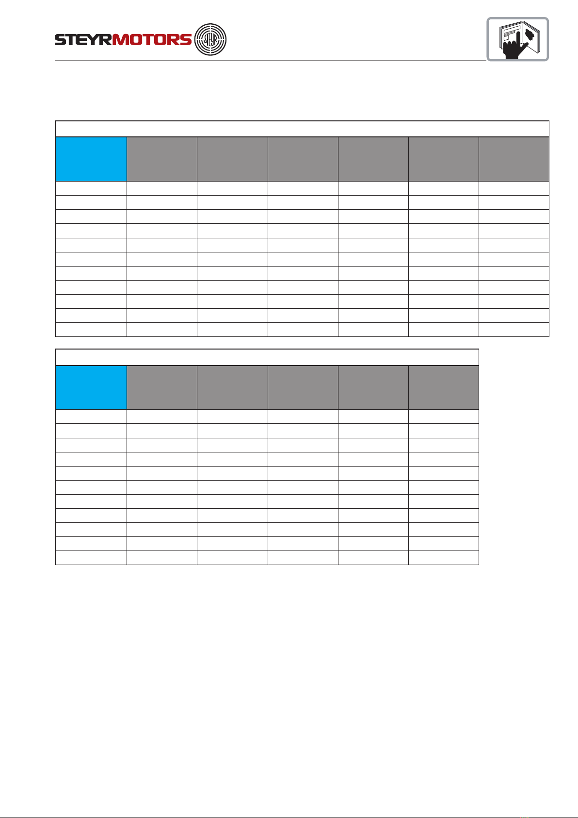
Marine 4 Cyl Engines Overview
MO & SE 4-cylinder engine models
engine type number of
cylinders
displacement
[cm³]
rated power
[kW]
rated speed
(rpm)
Propeller
selection
range (rpm)
Jet selection
range (rpm)
MO84K32 4 2100 55 3200 3000-3200 /
MO94K33 4 2100 66 3300 3100-3300 /
MO114K33 4 2100 81 3300 3100-3300 /
MO144M38 4 2100 106 3800 3500-3800 /
MO164M40 4 2100 120 4000 3700-4000 /
MO174V40 4 2100 125 4000 3700-4000 /
SE144E38 4 2133 106 3800 3700-3900 3300-3800
SE164E40 4 2133 118 4000 3900-4100 3550-4000
MO & SE 4-cylinder engine models
engine type dry weight
(kg)
Fuel cons @
rated power
(kg/h)
MAP
[mbar]
compression
ratio
max. exhaust
backpressure
(mbar)
MO84K32 243 14,2 1900 ε = 17,5 100
MO94K33 243 17,5 1900 ε = 17,5 100
MO114K33 255 18,6 1900 ε = 17,5 100
MO144M38 258 26,8 / ε = 17,5 100
MO164M40 258 31,6 2740 ε = 17,5 100
MO174V40 276 33,4 3100 ε = 17,0 150
SE144E38 263 27 2520 ε = 17,0 150
SE164E40 263 29,7 2650 ε = 17,0 150
MO & SE 4-cylinder engine models
engine type
backpressure
tolerance
(mbar)
max. engine
cooling water
outlet temp
(°C)
max. engine
coolant outlet
temperature
(°C)
Oil filling
quantity
[lt.]
Coolant water
quantity
[lt.]
MO84K32 +/-50 / / 8,4 9,0
MO94K33 +/-50 / / 8,4 9,0
MO114K33 +/-50 / / 8,4 9,0
MO144M38 +/-50 / / 8,4 9,0
MO164M40 +/-50 / / 8,4 9,0
MO174V40 +0/- 50 / / 8,4 9,0
SE144E38 +0/- 50 83 105 8,75 10,7
SE164E40 +0/- 50 83 105 8,75 10,7
13
Marine 6 Cyl Engines Overview
SE 6-cylinder engine models
engine type number of
cylinders
displacement
[cm³]
rated power
[kW]
rated speed
(rpm)
Propeller
selection
range (rpm)
Jet selection
range (rpm)
SE126E25 6 3200 88 2500 2300-2550 /
SE156E26 6 3200 110 2600 2400-2650 /
SE156E32 6 3200 110 3200 3000-3250 /
SE156E34 6 3200 110 3400 3200-3500 /
SE196E35 6 3200 140 3500 3300-3550 /
SE236E40 6 3200 170 4000 3900-4100 /
SE236S36 6 3200 170 3600 3400-3650 /
SE266E40 6 3200 190 4000 3850-4050 /
SE266S36 6 3200 190 3600 3300-3650 /
SE286E40 6 3200 205 4000 3900-4150 /
SE306J38 6 3200 215 3800 3500-3850 /
SE 6-cylinder engine models
engine type dry weight
(kg)
Fuel cons @
rated power
(kg/h)
MAP
[mbar]
compression
ratio
max. exhaust
backpressure
(mbar)
SE126E25 340 20,1 2130 ε = 17,0 150
SE156E26 340 25,4 2200 ε = 17,0 150
SE156E32 340 25,8 2280 ε = 17,0 150
SE156E34 340 25,1 2240 ε = 17,0 150
SE196E35 340 33,7 2280 ε = 17,0 150
SE236E40 340 42,5 2790 ε = 17,0 150
SE236S36 340 40,9 2560 ε = 17,0 150
SE266E40 340 47,3 2840 ε = 17,0 150
SE266S36 340 46,1 2740 ε = 17,0 150
SE286E40 340 51 2990 ε = 17,0 150
SE306J38 340 52,2 3060 ε = 17,0 150

14
SE 6-cylinder engine models
engine type
backpressure
tolerance
(mbar)
max. engine
cooling water
outlet temp
(°C)
max. engine
coolant outlet
temperature
(°C)
Oil filling
quantity
[lt.]
Coolant water
quantity
[lt.]
SE126E25 +0/- 50 81 105 17,0 15,5
SE156E26 +0/- 50 83 105 17,0 15,5
SE156E32 +0/- 50 83 105 17,0 15,5
SE156E34 +0/- 50 105
SE196E35 +0/- 50 83 105 17,0 15,5
SE236E40 +0/- 50 85 105 17,0 15,5
SE236S36 +0/- 50 86 105 17,0 15,5
SE266E40 +0/- 50 86 105 17,0 15,5
SE266S36 +0/- 50 86 105 17,0 15,5
SE286E40 +0/- 50 86 105 17,0 15,5
SE306J38 +0/- 50 87 105 17,0 15,5

15
Product References, Illustrations and Specifications
When reference is made in this manual to a brand name, number, product or specific tool, an equivalent product may
be used in place of the product referred to unless specifically stated otherwise. Equivalent products which are used
must meet all current local regulations and standards to avoid hazards.
Some countries may apply additional internal regulation. Please follow their advices appropriately, example:
Austria: Bundesamt für Schifffahrt
Sweden: Navigation Office
Finland: Navigation Office
Norway: DNV = Det Norske Veritas
USA: USCG = United States Coast Guard
USA: ABYC = American Boat Yacht Council
USA: NMMA = National Marine Manufacturers Association
England: LR = Lloyds Register of Shipping
France: BV = Bureau Veritas
Germany: GL = GERMANISCHER Lloyd
Italy: RINA = Registro Italiano Navale
All information, illustrations and specifications contained in this manual are based on the latest product informa-
tion available at the time of printing. STEYR MOTORS GmbH reserves the right to make changes at any time,
without notice, to specifications and models and also to discontinue models, as well as the right to change
specifications or parts at any time without incurring any obligation to equip same on models manufactured
prior to date of such change.
Continual accuracy of this manual cannot be guaranteed.
All illustrations used in this manual may not depict actual models or equipment and are intended as representative
views for reference only.
Insurance
Insurance on your STEYR MOTORS GmbH Marine Engine and boat should be obtained as soon as practical for
protection against loss by fire, theft, etc. Consult your local insurance agent.
Stolen Unit
The model and serial numbers on your engine are important for you. As to the location of these important numbers,
refer to Model and Serial Numbers in the section Technical Data.
Record each of these numbers in the spaces provided at the end of this manual and on a separate sheet. Store the
separate sheet in a safe place other than your boat.
In case of theft, report the model and serial numbers to your local authorities and your insurance agent.
Warranty Registration Approval
When you purchases your boat, your dealer was obliged to issue a Warranty Registration Approval for your
STEYR MOTORS Marine Engine.
This Warranty Registration Approval gives proof and is to be submitted in case of warranty claims.

16
Your STEYR MOTORS Marine dealer is also obliged to complete the Warranty Registration Approval (Chapter “War-
ranty”). Required tests and measurements are to be carried out from your STEYR MOTORS Marine dealer and sent
to STEYR MOTORS GmbH for approval of warranty registration.
Dealer Service - Maintenance
NOTE: Please do not forget to have confirmed in your manual that the installation and maintenance
have been carried out in accordance with the guidelines.
This is also an opportunity to clarify with your STEYR MOTORS GmbH marine dealer possible questions arisen dur-
ing the first running hours on your boat, and to establish a service- and maintenance routine.
Services will be performed by STEYR MOTORS GmbH Marine Dealers at local rates.
Costs for service material to be paid by the owner.
Illustration Symbols
Refer to the photograph or drawing described in
that paragraph.
Refer to specific items or features described in the
text and illustrated on the photograph.
Refer to the general subject of the text.
Refer to an item or feature not clearly visible on
the photograph.

17
Repair Service
All repair works on your STEYR MOTORS GmbH marine engine should be carried out by a licensed STEYR MO-
TORS GmbH Marine Dealer with his professional knowledge, trained staff and special-purpose tools to solve all oc-
curing problems. Preferably, all work on your STEYR MOTORS GmbH marine engine should be carried out by the
STEYR MOTORS GmbH Marine Dealer that sold the equipment to you - he knows you and the equipment.
If problems occur during a trip, bring your engine to the next STEYR MOTORS GmbH Marine Dealer.Information
on Dealers and Distributors can be found at the end of this manual.
Replacement Parts
Your STEYR MOTORS GmbH Marine Engine was designed to operate in a marine environment use STEYR MO-
TORS GmbH original replacement parts.
Before Casting Off
Check the weather report, wind and water conditions. Tell someone where you are going to and when you expect to
arrive or return.
Recommended Minimum
On-Board Tools
Screwdriver Set lubrication oil spray
Metric Socket Set 12-volt pilot lamp
Metric Allen Key Set flashlight
Metric Spanner Set insulating tape
long nose pliers sharp knife
Recommended Minimum
On-Board Spare Parts
propeller and small parts for propeller mounting fuses
fuel filter ( pre- & finefilter) bulbs
impeller for raw water pump sealing compound
These lists represent a suggested MINIMUM,and are not intended to cover all boats or possible boating conditions.

18
Engine Submersion
Remove engine from water as quickly as possible and contact your local STEYR MOTORS GmbH Marine dealer for
service.
It is imperative that your dealer removes all water from the engine and immediately relubricates all internal parts.
Electrical devices must be replaced. Delay in completing these actions may allow extensive engine damage.
Frequently check engine compartment for excessive water accumulation; water depth in bilge should be kept well
below flywheel housing. Engine compartment must enable proper venting to avoid condensation to build up on inner
surfaces.
Bottom Painting
If your boat is in water where marine growth is a problem, the use of an antifouling paint will reduce the growth rate.
* Tin base antifouling paint (TBTA or TBTF) is recommended where its use is permitted.
* Copper base antifouling paint may be used, but will require more frequent inspection and replacement of sacrificial
anodes. DO NOT PAINT any part of the drive unit with copper base antifouling paint.
NOTE: Painting the drive unit with copper base paint will accelerate galvanic corrosion.
* Vinyl-butyl base antifouling paint is a recommended alternative.
*DO NOT USE any graphite base antifouling paint.
NOTE: Never paint anti-corrosion anodes, or their effectiveness will be lost.
See your STEYR MOTORS GmbH Marine contract partner for an antifouling paint that is
suitable for your area.
Boat Bottom
The condition of the boat bottom can affect your boat’s performance. Marine growth, present in fresh water as well
as salt water, will reduce boat speed. A boat bottom with evidence of marine growth causes a reduction in top speed
of 20 percent or more. Periodically clean the bottom of your boat following the manufacturer’s recommendations.

19
Boating Responsibilities
As a boat owner, you have certain responsibilities to others. Be sure that all operators read this manual.
You are legally responsible for all occupants of your boat. Instruct at least one of your passengers in the basic fun-
damentals of handling your boat in case of an emergency. Show all hands the location of emergency equipment and
how to use it. You are required by law to have one locally approved life jacket for each person aboard, plus one ap-
proved throwable device for man overboard protection.
Learn the waterway rules of the location in which you are going to operate your boat. Navigable waterways are con-
trolled by Federal regulations while inland lakes are controlled by local jurisdictions. Obey these regulations to protect
yourself, your passengers and fellow boating enthusiasts.
Thoroughly familiarize yourself with weather station warning system signals and waterway traffic signs.
Contact your local Coast Guard station and take advantage of their seasonal boat inspections and training courses.
Safety
This manual contains certain information related to the personal safety of you the operator, your passengers and
bystanders.
The Safety symbol ATTENTION: appears next to important information to prevent you and others from being
hurt.
The symbol NOTE: appears next to important information to keep machinery from being damaged.
Observe all notes and safety warnings contained in this manual.
WARNING
CALIFORNIA: PROPOSITION 65 WARNING
Diesel engine exhaust and some of its constituents are known to the state of California to cause cancer, birth defects,
and other reproductive harm.

20
Symbols
Certain symbols or combinations of symbols may appear on your STEYR MOTORS GmbH Marine Engine or on its
accessories. It is very important that you understand their meaning or purpose. If any symbol is not clearly under-
stood, see your DEALER.
"Safety Warning" Symbols
Means risk of SERIOUS injury is
present. Follow instructions in the
Operation, Maintenance & Warranty
Manual before using motor or
accsessory.
Means place shift control in
NEUTRAL before starting motor.
Follow instructions in Operation,
Maintenance & Warranty Manual
before starting motor.
Indicates that ELECTRICITY of
more than 50 volts is present.
Indicates that contents are under
pressure.
Identifies poisonous material. Indicates a potential fire hazard.
"Position Indicator" Symbols
Indicates upward movement.
Example: While boat is at planing
speed, activating trim switch to raise
the bow of the boat.
Indicates downward movement.
Example: While boat is at planing
speed, activating trim switch to
lower the bow of the boat.
Indicates gear shift control positions:
FORWARD, NEUTRAL and
REVERSE
"Condition" Symbols
Identifies the meter which indicates
accumulative running hours of
engine.
Identifies the meter which indicates
battery voltage or amperage.
Identifies the meter which indicates
engine speed expressed in
revolutions per minute.
Identifies battery or a meter which
indicates status of battery-generator
charging system.
Indicates the amount of liquid in
tank.
Identifies the meter which indicates
engine coolant pressure.
Identifies the meter which indicates
engine coolant temperature.
FILTER: Identifies a device which
removes contaminants from
engine’s oil system.
Identifies the meter which indicates
the pressure of engine’s lubricating
system.
"Functional Description" Symbols
FILTER: Identifies a device which
removes contaminants from fuel.
Identifies the EMERGENCY
IGNITION CUT-OFF SWITCH.
Emergency engine stop.
FUSE: Identifies a device which
protects the electrical system from
overload.
Identifies the negative ground or
negative voltage connection.
Identifies engine drain plugs and
fittings.
Identifies the operating device for
starting the motor.
Identifies the STOP SWITCH.
It may also identify STOP position of
the throttle control.
"Instructional" Symbols
Indicates FUEL is to be used or
FUEL is present.
Means read your Operation,
Maintenance & Warranty Manual
before operating the product. It
contains information or instructions
vital for operation of product.
Indicates areas to be lubricated.
Indicates OIL is to be used or
OIL is present.
ENGINE OIL FILL: Location for
introduction of oil into the engine.
Indicates lubricating oil used in
transmissions.
This manual suits for next models
18
Table of contents
Other STEYR MOTORS Engine manuals


Popular Engine manuals by other brands

Shindaiwa
Shindaiwa DG1000MI Owner's and operator's manual

Panasonic
Panasonic M41A1G4L operating instructions

Nice
Nice NEO S Installation and use instructions and warnings

SOMFY
SOMFY Tilt & Lift 25 RTS Central instructions

MTD
MTD 679 cc EFI OHV Operator's manual

Briggs & Stratton
Briggs & Stratton P0820B Operator's manual

Volvo Penta
Volvo Penta D4 Operator's manual

Rotax
Rotax MML-912 Maintenance manual

O.S. engine
O.S. engine MAX-105HZ-R instruction manual

GEIGER
GEIGER PRO.TECline GB45 M01 Series Original assembly and operating instructions

MINN KOTA
MINN KOTA ULTERRA QUEST Quick reference guide

teching
teching Craftsman DM17-S-T Product description


