Shindaiwa DG1000MI User manual

OWNER’S AND OPERATOR’S MANUAL
Vertical, Water-Cooled 4-Cycle Diesel Engine
DG1000MI/ANZ
X753-005 27 2
X753800-000 2
CAUTION
Do not operate the Generator, or any other appliance, before you have read and
understood the instructions for use and keep near for ready use.


Introduction
Thank you forpurchasing thisShindaiwa soundproof diesel engine generator.
This manual has been created to ensure safe usage ofthis generator.Be sure to read this
manual before operation.Improperoperation/handlingof thisgeneratorwillresultinanaccident
or malfunction.
Handling/Operation of this generatorcanonlybe performed bypersonswho understandthe
contents ofthismanual and canhandle/operate thegeneratorin a safemanner.Persons who
sufferfrom an illness, are taking medicine or not feeling waysuchthat safe operation would be
negativelyaffectedmustnotoperate this generator.
Workperformedusingthisgeneratorandhandling/operationofthisgeneratormustbe in
accordance with corresponding laws and regulationsbased on such laws.Consult with the
authorizeddistributorwherethis generatorwaspurchasedif youhaveanyinquiriesregarding the
correspondinglaws.
Always be sure to include this manual when loaning out this generator and instruct operating
personnel to read thismanualbeforeoperation.
Store this manual in a specified location where itwill be secure andavailablefor consulting at any
time.Order anothercopyfromtheauthorizeddistributorwhere thisgeneratorwaspurchasedif
thismanualbecomes dusty, grimyor torn.
Consult with the authorized distributor where this generator was purchased if you have any
inquiries regarding any points relatedtothis generator and manual.
When inquiringaboutthis generator,besure to providethemodel nameandserial number.
If disposing of this generator, do so in a manner that is in compliance with laws related to
industrialwaste. Contactthe authorized distributor where the generator was purchased if you
have any inquiries regardingproperdisposal.
Caution notice ranks in this manual are classified as follows.
WARNING : Indicates a potentially hazardous situation which, if not
avoided, can result in death or serious injury
CAUTION : Indicates a potentially hazardous situation which, if not avoided,
can resultinminor or moderate injuryandpropertydamage.
< NOTE > : Othertypes ofcautionsandindications.
Note that CAUTION itemscanalsoleadtomajoraccidents undersomecircumstancesif
notcorrectlyfollowed.
All cautionnotices areimportant.Besuretofollow all ofthem.

1
Table of Contents
1.
Safety Instructions .......................................................................... 2
2.
Specifications................................................................................... 5
2-1.
Specifications............................................................................5
2-2.
Ambient Conditions................................................................... 6
3.
Applications..................................................................................... 6
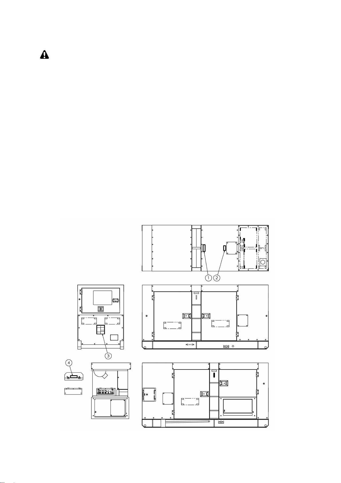
4.
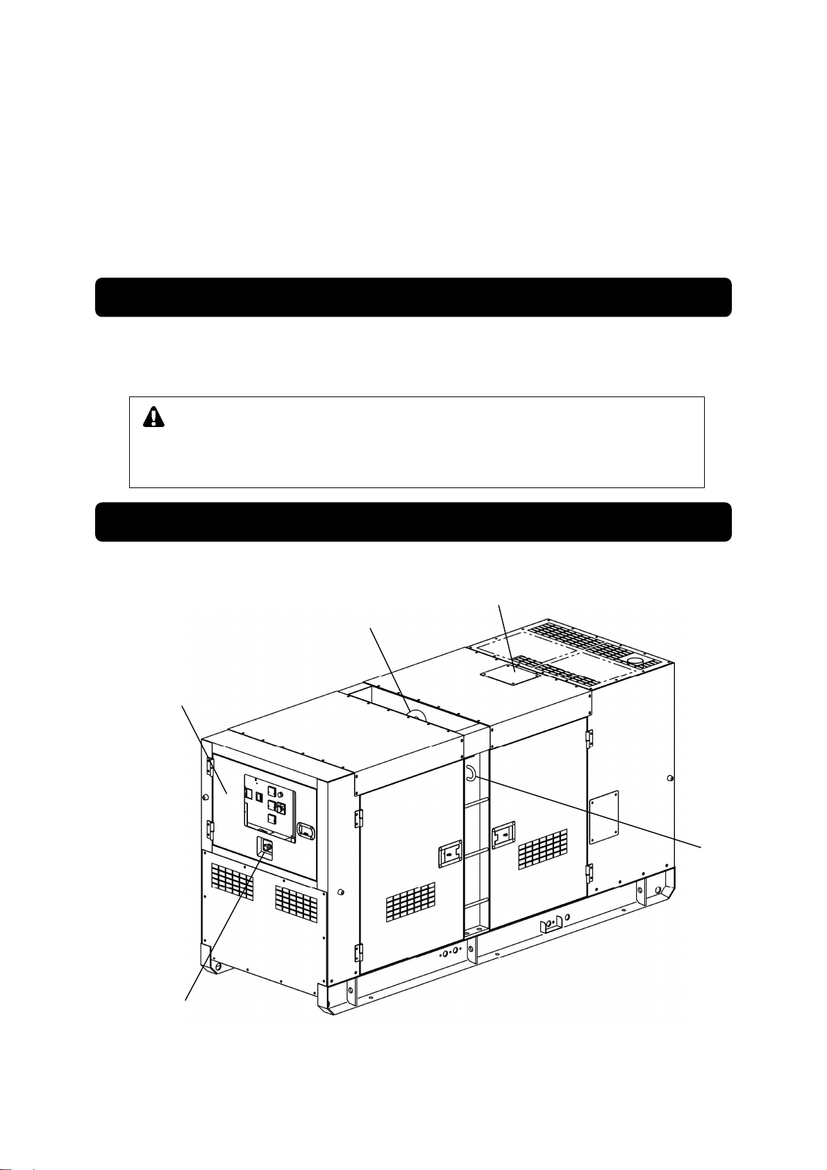
Part Names....................................................................................... 6
4-1.
External View/Part Names ........................................................6
4-2.
Operation Panel Part Names ....................................................8
4-3.
Main Terminal Board ................................................................. 8
5.
Equipment........................................................................................ 9
5-1.
Warning Indicators ....................................................................9
5-2.
Meters and Gauges................................................................. 11
5-3.
Fuel Piping Switch (3Way Fuel Valve)..................................... 16
6.
Transporting/Installing.................................................................. 17
6-1.
Transport Procedures.............................................................. 17
6-2.
Installation Procedures............................................................ 18
7.
Load Connections ......................................................................... 19
7-1.
Load Cable Selection..............................................................19
7-2.
Connecting Load Cables.........................................................20
7-3. Earth Leakage Relay and Grounding ....................................... 21
8.
Pre-Operation Inspection.............................................................. 24
8-1.
Checking Engine Oil................................................................ 24
8-2.
Checking Coolant.................................................................... 25
8-3.
Checking the Fan Belt.............................................................27
8-4.
Checking the Fuel ................................................................... 28
8-5.
Checking for Fuel, Oil and Coolant Leaks...............................29
8-6.
Checking the Battery............................................................... 29
9.
Operating Procedures................................................................... 31
9-1.
Initial Startup/Pre-Check.......................................................... 31
9-2.
Procedures during Operation.................................................. 33
9-3.
Stopping Operation ................................................................. 33
9-4.
Protective Functions................................................................ 34
9-5.
Connecting with External Fuel Tank........................................ 35
10.
Inspection/Maintenance................................................................ 36
11.
Long-Term Storage........................................................................ 44
12.
Troubleshooting............................................................................. 45
13.
Generator Circuit Diagram............................................................ 48
14.
Engine Electrical Circuit Diagram ................................................ 49

2
1. Safety Instructions
WARNING : SUFFOCATION FROM EXHAUST FUME
Do notoperate the generator in poorly ventilated areas such as indoors or tunnels,asthe exhaust
gas ofthe engine contains substances that are harmful to humanhealth.
Do notdirect exhaust fumes at pedestrians or buildings.
WARNING : ELECTRIC SHOCK
Beforeconnectingordisconnecting theloadcables to/fromtheoutputterminal,always turnthe
output circuitbreakers to the OFF position,stop the engine, and remove the engine key.
Closetheoutputterminalcoverbefore operating.
Do notinsert a pin,wire or other metal object into the electrical outlet.
Do nottouch thegeneratoriftheAlternator or casing becomes wet during operation.
Do nottouch output terminalsor internal electric parts while the generatoris operating.
Ground the everyearthgroundingterminalto the earthassetoutinthe manual.
Ifeven one of all is unconnected by mistake or accident, it will be muchmore dangerous for
human body than the NO-RELAY case, because leaking current inevitably goes throughthe
body.
Even though all theearth terminals of the loads have been grounded to the earth, thebonnet
grounding terminal should be grounded tothe earth.
Thereis always a danger of being electrocuted by short-circuit. Be sure to test generator’s
insulationresistanceperiodically.
Groundingshould be madeaftertheengine is stopped.
Whenever the Earth leakage breaker is activated,you should always repair the leaking place first
ofall.
WARNING : INJURY
Closeall doors and lock them during operation.
Closealldoorsand placelocksduringoperating thisequipment,toavoidinjuriesby
unintentionally touchingcooling fan and fanbelt.
Before performinganyequipmentcheckormaintenance,stopthe engine, andremove the
engine key.Aperson performingthe maintenanceshould always keep the key.
Use the lifting hook to lift the machines, anddo not lift up the unitusing tie-downs. Useof such
could result in the generatorfalling.
Donotlift anyadditionalweightsuch asfueltanksortrailers.
No persons should be under a lifted generator.
Before turning the circuit breakertoON position, ensure that the breaker or theswitch of loads
are positioned to OFF.
Operatethecircuit breaker,well-communicatingwiththeelectricianbytheloadside.

3
CAUTION : EYE/SKIN INJURY
Wear rubber gloves andother protective wear to protecteyes, skin and clothing from thebattery
fluidwhich containsdiluted sulfuricacid. If the battery fluidcontacts eyes or skin, wash out
immediatelywith asufficient amountofclean water. Besure to receive medicaltreatment,
especially if the fluid contacts the eyes.
CAUTION : EXPLOSION
Neveruse or recharge thebattery if the fluid level is below the minimumlevel.
Donotcreatesparksorbringflamenear thebattery asitgenerates flammablegas.
CAUTION : FIRE
Do notbring flammable items (such as fuel,gas and paint)oritems that are highly combustible
near the generator as the muffler, exhaust gas and other parts become extremely hot.
Keep this generator 1m or more from walls or other hindrances, and on a level surface.
Donotconnectthegeneratoroutput toindoor wiring.
This generatoruses dieselfuel.Always be sure to stop the engine and not bring flames close
when inspecting fuel orrefueling. Wait until the enginehas cooled before performing such
procedures.
Do notuse this equipment when leak is found, and repair the leaking location before operating.
Alwaysbe suretowipe up anyspilled fuelor oil.
Allow the generator to cool before covering with theprotective cover.
Neverallow flame to come close to the generator.
CAUTION : BURNS
Do nottouch the engine and surrounding components immediately after stopping the equipment,
whiletemperaturecanreach extremely high.
Do notopen the radiator capimmediately after stopping theengine, to avoid sustaining burns
fromhotvapor.
Hot steam gushes out from thecoolant sub-tank if thegenerator overheats.Donot touch the
coolantsub-tank.
Alwaysbe sure to stop the engine andallow the engine to cool when performing inspection or
maintenance of engine oil. Opening the oil level indicator or oil fillercap during operation will result
inhotoilcausepersonalinjury.
CAUTION : INJURY
Alwaysbe sure to use lifting hooks when moving the generator, and lift it slowly at a completely
verticalangle.
Personnel performing liftingwork mustwear protective gear such as helmets, safety shoes and
gloves.
Remove the wood ties ifusing anchors to secure the generator.
Position thegenerator on a level stable surface so that it cannotslide or movein any manner.
Before starting operation,always be sure to turn off all switches of equipment using the generator
and allbreakerstoOFF.
Do notmove the generator during operation.
Do notoperate the generator if it has been modified oranyparts have been removed.

4
CAUTION : PROPERTY DAMAGE
If using this generator for medical equipment, check before use with the medical equipment
manufacturer, doctor, hospitalor similar entity.
Check that thegenerator output setting,output terminalconnection and load powersource are
consistent.
Cable burnout can occurdue to generatedheat if the loadcurrent exceeds the allowable current
ofthecable.
The voltage drop between cables is large if the cable is excessively long or thin, resulting in
decreasedinputvoltage to equipmentusingthegenerator,therebycausing decreased
performance, faulty operation and malfunction.
Warning/Caution Label Locations
If warning or caution labels become damaged and difficult to read, replace with new labels in
the indicated locations. Order labels using part number indicated in the parenthesis.
Injury (Part no. :X505-004630)
Caution: gm spec LLC (Part no. :X505-004650)
Danger caution
(Part no. :X505-004660)
Danger
: Electric Shock (Part no. :X505-004640)

5
2.
Specifications
2-1. Specifications
Model Unit DG1000MI/ANZ
Alternator
Generating Type - Rotating Filed, Brushless 3-Phase
Synchronous Alternator
Rated Output kVA 80
kW
64
Rated Voltage V 415
Rated Current A 111
Rated Frequency Hz 50
Winding - 3-phase, 4-wire
Power factor % 80
Insulation class - H
Excitation - Self-Excitation(Brushless)
No. of poles - 4
Engine
Types - Vertical Water-cooled 4-cycle Diesel Engine
Model (Manufacturer) - DD-6BG1T(ISUZU)
No. of Cylinders (bore x stroke) mm 6 (105 x 125)
Continuous rated output kW 73.1
PS
99.4
Rated speed
min
-
1
1500
Displacement L 6.494
Combustion system - Direct Fuel Injection with Turbo Charger
Cooling method - Radiator
Lubricating method - Forced lubrication
Starting method - Electric start
Fuel - Diesel Fuel (ASTM No. 2-D)
Lubricant oil - CD class
Fuel tank capacity L 219
Lubricant volume (Full) L 22
Cooling water volume L 22.8
Starting motor capacity V-kW 24 - 4.5
Charging dynamo capacity V-A 24 - 30
Battery - 95D31R x 2
Unit
Length
mm
2750
Width
mm
1000
Height
mm
1400
Dry Weight
kg
1800
Installed Weight
kg
2041

6
Lifting Hook
Tie-Down
Operation Panel Door
Emergency Stop Button
Radiator Plate
2-2. Ambient Conditions
Use this generator in ambient conditions as described below. Failure to provide these
conditions can result in problems such as malfunction, insufficient output and reduced
durability.
■
Ambient temperature: -15 to 40 degree Celsius
■
Relative humidity: 80% or less
■
Elevation: 300 m or less
3. Applications
Power source for submerged pumps and similar civil engineering equipment
Power source for lighting and similar equipment
Power source for electrical tools and household appliances
4. Part Names
4-1. External View/Part Names
CAUTION : PROPERTY/SECONDARY DAMAGE
Do not use for any application other than those listed above.
If using this generator for medical equipment, check before use with the
medical equipment manufacturer, doctor, hospital or similar entity.

7
Fuel Inlet
Fuel Tank
Coolant Sub-Tank
Engine Check Door
Battery
Alternator Check Door
Oil Level Indicator
Tie-DownOil Filler Cap
Oil Drain Plug
External Tank Fuel Inlet
External Tank Fuel Return
Fuel Drain plug
Coolant Drain plug
Water Separator
Battery
Alternator Check Door Engine Check Door
Fuel Filter
Oil Filter
Radiator
Air Cleaner
Tie-Down
Terminal Cover
Terminal Cover
Accessories
Owners
Manual
Engine
Warranty
Engine Key (2 pieces)

8
4-2. Operation Panel Part Names
①
Circuit Breaker
⑩
Hour Meter
②
Earth Leakage Relay
⑪
Water Temperature Gauge
③
Voltmeter
⑫
Fuel Gauge
④
Ammeter
⑬
Preheat Lamp
⑤
Frequency Meter
⑭
Starter Switch
⑥
Panel Light & Pilot Lamp
⑮
Throttle Lever
⑦
Voltage Regulator
⑯
Frequency Adjusting Screw
⑧
Ammeter Selector Switch
⑰
Emergency Stop Button
⑨
Warning Indicators
⑱
Battery Isolator
4-3. Main Terminal Board
Main Terminals
Plexiglass Cover

9
5. Equipment
5-1. Warning Indicators
The equipment is incorporated in monitoring function of WATER TEMP, BATTERY
CHARGING & OIL PRESSURE.
Under normal condition, when the starter switch changes from STOP to RUN, all the
lamps of BATTERY CHARGING and OIL PRESSURE turn ON. When the engine
starts, all the lamps turn OFF.
When abnormality is detected about WATER TEMP and OIL PRESSURE, the
corresponding monitor lamp will flash, and the engine is automatically shutdown.
When the automatic shutdown is engaged, turn the starter switch to STOP position
once, and then restart the engine. In the event the automatic shutdown happens
after that, check which lamp turns ON or OFF and point out where is the
abnormality.
WARNING : INJURY
Close all doors and place locks during operation, to avoid injuries by
unintentionally contact with moving parts such as the cooling fan and fan belt.
Before performing any equipment check or main
tenance, stop the engine, and
remove the engine key.A person performing the maintenance should always
keep the key.
CAUTION : BURNS
Do not touch the engine and surrounding components immediately after
stopping the equipment, while temperature can reach extremely high.

10
(1)WATER TEMP (Coolant Temperature) Warning Indicator (High Water Temp.)
CAUTION: BURNS
Do not open the radiator cap immediately after stopping the engine, to avoid
sustaining burns from hot vapor.
Hot steam gushes out from the coolant sub-tank if the generator overheats.
Do not touch the coolant sub-tank.
When the water temperature reaches 105 degree Celsius, the
coolant/water temperature monitor lamp will flash, and the automatic
shutoff will be engaged.
When this occurs, check the coolant/water reservoir tank, and replenish
if needed.
(Refer to “
8-2. Checking Coolant
”.)
If the water level is normal, there may be a possibility of loose fan belt or water leakage in
coolant lines. Check it after the engine cools down.
< NOTE >
The coolant temperature cannotbe detected ifthe coolantlevel is excessively low.Always be
suretocheckthecoolantlevel in theradiator coolantsub-tankbeforestarting work.
(2) OIL PRESS (engine oil pressure) Warning Indicator (Low Oil Press.)
CAUTION: BURNS
Always be sure to stop the engine and allow the engine to cool when
performing inspection or maintenance of engine oil. Opening the oil gauge or
oil filler cap during operation will result in hot oil cause personal injury.
When the engine oil pressure drops below 0.98 x 100kPa {1kgf/cm
2
}
during operation, the oil pressure monitor lamp will flash, and the
automatic shutdown will be engaged.
When this occurs, check the engine oil level, and replenish to the
maximum level if needed.
< NOTE >
This oil pressure warning indicatorcannot detect oildeterioration. Change the engine oil
periodically.(Refertosection“8-1.Checking Engine Oil”.)
(3) BATTERY (Battery Charge) Warning Indicator (Low Battery Voltage)
The BATTERY warning indicator lights up when charging is not possible during
operation. If this occurs, contact the authorized distributor where the generator
was purchased.
< NOTE >
This battery charging warningindicatorcannotdetectbattery deteriorationorinsufficientbattery
fluid.(Refertosection“8-6. Checking the Battery”.)
WATER TEMP
OIL PRESS
CHARGE

11
5-2. Meters and Gauges
Engine Meters and Gauges
(1) Hour Meter
Displays the operating time. Use this to schedule periodic
inspection. Be careful as the hour meter operates when the starter
switch is at RUN regardless of whether the engine is running or
stopped.
(2) Water Temperature Gauge
Water Temperature Gauge displays the temperature of engine
coolant. Normal temperature may vary depending on the
environment, but it should be between 75 to 90 degrees Celsius.
< NOTE >
If the temperature exceedsnormalvalue,disconnecttheload,
idle theengineat1000min
-1
, andwait until the reading falls to
the normal temperature range.
(3) Fuel Gauge
It shows the volume in the fuel tank.
When filled up, it shows 『F』.
When the hand is approaching to『E』, the volume is coming to
empty. Replenish fuel enough promptly.

12
Generator Meters and Gauges
(1) Voltmeter
Voltmeter displays the output voltage (Phase to Phase) from the
generator.
Please check and confirm it showing 415V at 50Hz during
operation.
(2) Ammeter
Ammeter displays the output current (Phase) from the generator.
(3) Frequency Meter
Frequency Meter will display the frequency of the generator.
Please check it showing 50Hz during operation.
Lamps
(1) Preheat Lamp
When the start switch is turned to <Pre-heating> position, the
Preheat (Status) Lamp will be turned on in 25 seconds, indicating
that the preheating is completed.
(2) Panel Light & Pilot Lamp
Pilot Lamp indicates whether or not generator is generating
electricity, when the engine is driving

13
Switches
(1) Starter Switch
① Stop
When the switch is set to this
position, all power will be off.
The switch must be set to this
position to remove the key.
②Run
The switch must be set to this position during operation.
< NOTE >
Do not leave the switch to this position, while the engine is stopped. Otherwise
the battery is discharged.
③Start
This position will allow user to start the engine. When the key is released,
the setting will automatically return to <RUN> position.
④ Preheat
This position will allow generator to preheat Glow Plug during startup in cold
environment.
(2) Emergency Stop Button
This button is used to stop the engine in emergency.
By inserting the button, the engine stops.
Be sure to restore the starter switch to STOP and re-set
the button, turning clockwise after using the emergency stop
button.
(3) Circuit Breaker
By turning this circuit breaker on the control panel to ON,
Power will be transferred to the output receptacles and to the
load side.
The breaker trips to OFF, either overload or short-circuit.
STOP
RUN
START
PREHEAT

14
(4) Thermal Relay This relay sends the signal to the circuit breaker to trip-off
when over-current flows in the circuits.
When the breaker trips-off, it is set at the middle of ON and
OFF. In the case, please recover the breaker, according to
the following procedure;
①Stop the engine.
②Open the control panel and push the reset button of
the thermal relay.
You can recover the breaker to the ON position.
< NOTE >
Do not change the preset value of the thermal relay.
(5) Ampere Meter Selector Switch
The phase current displays in the meter, by switching to each
phase (L1,L2,L3) position.
(6) Battery Isolator When turning the switch to OFF, the engine
electric circuit does not activate due to no
battery power.
(7) Earth Leakage Relay Unit
Sensing the earth leakage current, the unit (relay) send a signal to the
3-phase breaker to trip-off in order to shut-off The circuit to the terminals
(loads).
(Refer to section “7-3. Earth Leakage Relay and Grounding”.)
Thermal Relay
OFF position ON position
Reset Button

15
Voltage Regulator and Throttle Lever
(1) Voltage Regulator
The dial adjusts generator output voltage.
By turning the dial clockwise, an operator can increases the voltage.
By turning the dial counter-clockwise, an operator can decrease the
voltage.
(2) Throttle Lever
① Throttle Lever
The lever is to adjust the engine speed.
Set it to <START POSITION>when the engine
starts and warms-up or cools down.
When the rated power is used, set it to
<RUN POSITION>(50Hz).
② Frequency Adjusting Screw
Set the throttle lever to <RUN POSITION>and
loosen the fixing Screw nut.
Turn the screw to<INCREASE>to get high
frequency and to<DECREASE>to low frequency.
< NOTE >
The equipmentisset it at 50Hz anddelivered.
You can get the frequencyof 50Hz under the rated output load in case adjusting it as per the
followingfrequencyundernoload.
No-load frequency(Revolution)
50Hz Operation 52.5Hz(1575min
-1
)
RUN POSITION
START POSITION
DECREASE
INCREASE
FREQUENCY ADJUST
THROTTLE LEVER
Throttle Lever
FrequencyAdjusting Screw
Fixing Screw Nut

16
5-3. Fuel Piping Switch (3Way Fuel Valve)
CAUTION:
Always make sure that the engine is stopped when working on fuel line.
Always be sure to wipe up any spilled fuel.
After working on the piping, check that there is no Diesel fuel leakage.
By switching
three-way fuel valve fuel will be supplied from the external tank.
In that case, the built-in tank will not be used.
(1)
Using fuel from built-in fuel tank
The lever for 3-way valve is set to Awhen the equipment is shipped. In addition, both
the external fuel intake and the external fuel return are safeguarded with PT-1/2 plugs.
Do not remove the plugs, when using the built-in fuel tank.
< NOTE >
Always set the lever for 3-way valve back to Aposition and cover the external
fuel intake and return port with the supplied plugs, after the hoses are removed.
(2)
Using fuel from external fuel tank
Connect hoses from the external fuel tank to the external fuel intake and the
external fuel return ports, and set the lever for 3-way valve to Bposition.
You can now supply the fuel from the external fuel tank.
For detail instruction, refer to
“9-6. Connecting with External Fuel Tank”
(<A>position
)
3-Way valves
外部燃料供給口 外部燃料戻り口(プラグ PT1/2)
EXTERNAL
FUEL
INTAKE
(PLUG
:
EXTERNAL
FUEL
RETURN
(PLUG
:
3-Way
3-Way valves
(<B>position)
To EXTERNAL FUEL TANK

17
6.
Transporting/Installing
6-1. Transport Procedures
WARNING : INJURY
Use the lifting hook to lift the machines, and do not lift up the unit using tie-downs. Use
of such could result in the generator falling.
No persons should be under a lifted generator.
CAUTION : INJURY
Always be sure to use lifting hooks when lifting up the generator, and raise it
slowly at a completely vertical angle.
Personnel performing lifting work must wear protective gear such as helmets,
safety shoes and gloves.
Do not move the generator during operation.
(1) Lifting Procedures
Always be sure to use lifting hooks when lifting up the generator, and raise it slowly at a
completely vertical angle.
(2) Transport
When transporting this generator, tie rope to the left and right tie-downs, and securely fix the
generator.
< NOTE >
Handlethis generatorwith extreme care when raising, lowering and transporting.Rough handling
of this generator may result in damage or malfunction.
Lifting Hook
Tie-Down
Other manuals for DG1000MI
1
This manual suits for next models
1
Table of contents
Other Shindaiwa Engine manuals

Shindaiwa
Shindaiwa DGM60MK User manual

Shindaiwa
Shindaiwa M262 User manual

Shindaiwa
Shindaiwa DGW400DML User manual

Shindaiwa
Shindaiwa DG15BMK User manual

Shindaiwa
Shindaiwa DGW300MS/UKV User manual

Shindaiwa
Shindaiwa DGW200MS/UKV User manual

Shindaiwa
Shindaiwa DGW400DMK User manual

Shindaiwa
Shindaiwa DG1000MIM User manual

Shindaiwa
Shindaiwa DGW310MC User manual