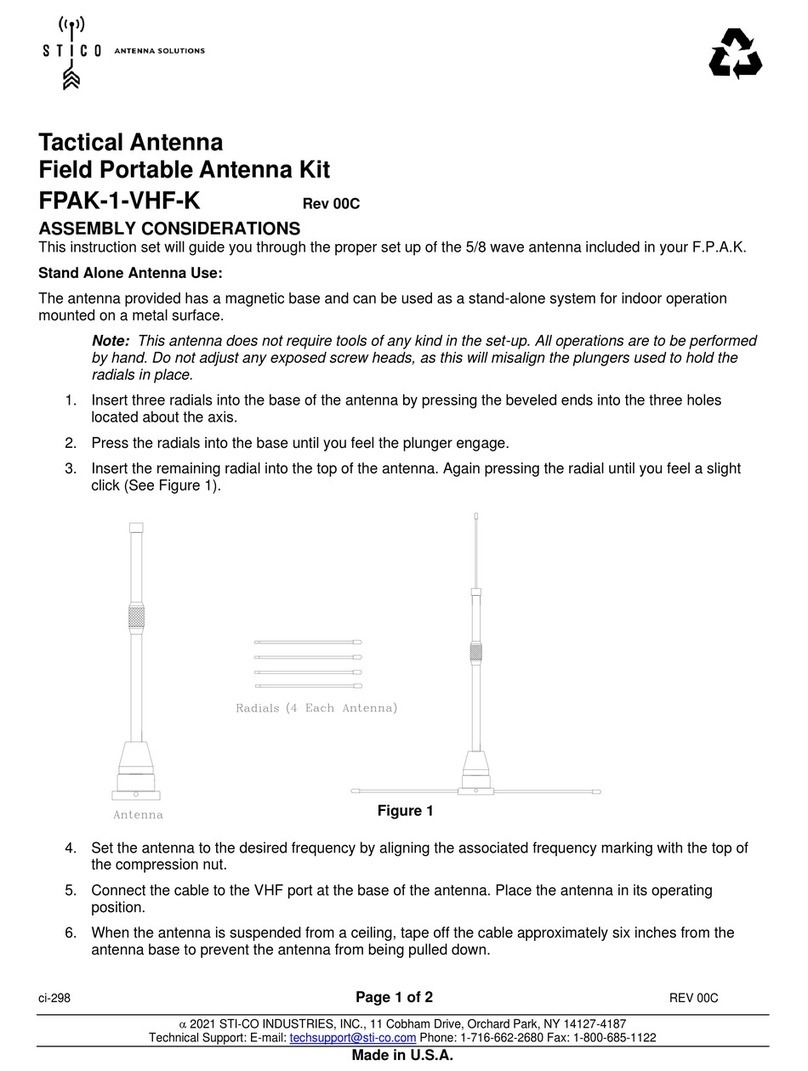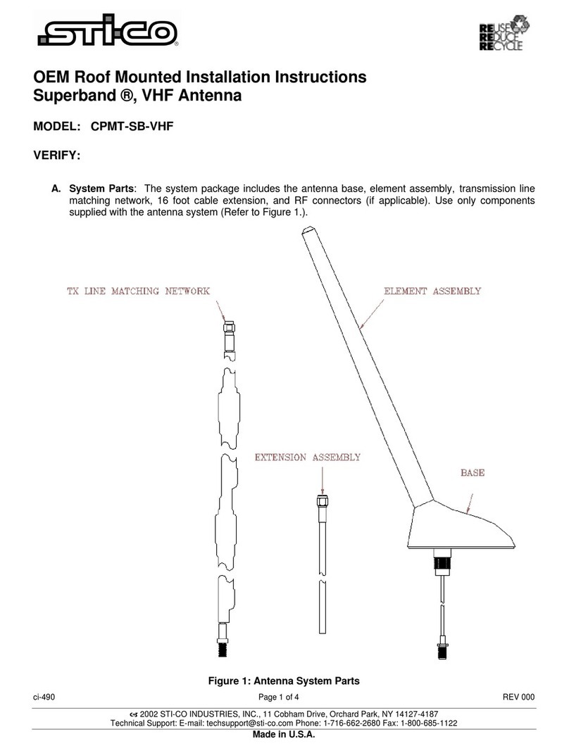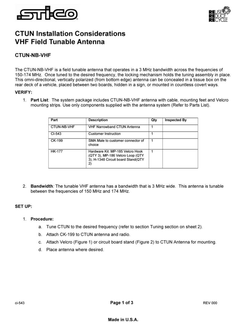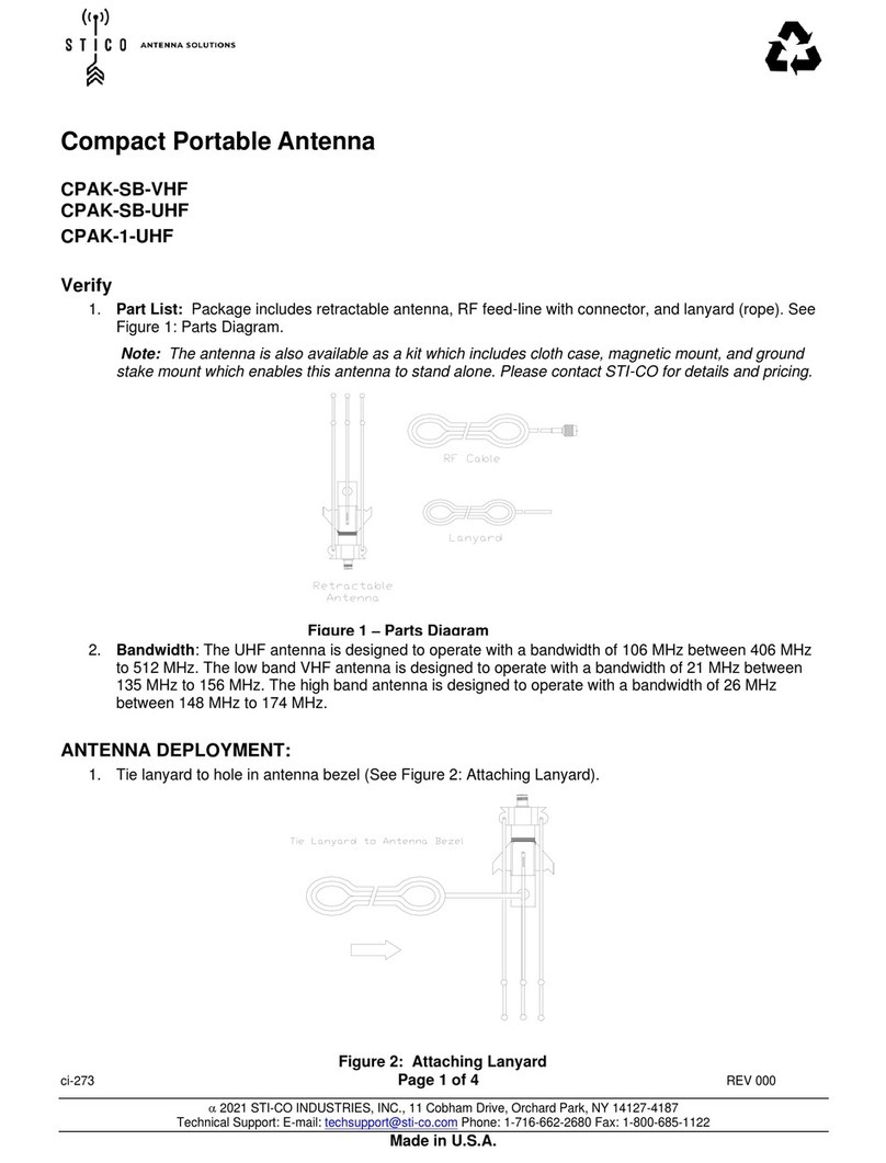
CI-545 Page 2of 2REV 000
a2002 STI-CO INDUSTRIES, INC., 11 Cobham Drive, Orchard Park, NY 14127-4187
Technical Support: E-mail: techsupport@sti-co.com Phone: 1-716-662-2680 Fax: 1-800-685-1122
Made in U.S.A.
INSTALLATION:
A. Antenna Mounting Location
This antenna may be mounted anywhere on the metal roof or metal trunk of the vehicle. Do NOT mount this
antenna on a fiberglass or composite surface.
WARNING! If the antenna is not mounted as described above and depicted below it will likely not
function as designed. The operator will likely see a sharp increase in SWR if not mounted properly.
B. Antenna Mounting Procedure
1. Remove “one way clips” on the inside roof panel near the window and set aside.
2. Remove OEM antenna connection for the AM/FM radio. Note: Some applications do not have
existing OEM antennas. In that case a ¾” hole is required.
3. Using an adjustable wrench, remove the OEM antenna.
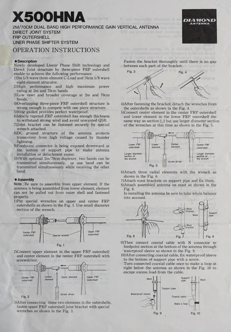
4. Position the disguised antenna mount into the mounting hole from the top of the vehicle. Note: This step
may require an assistant to hold and align the new antenna.
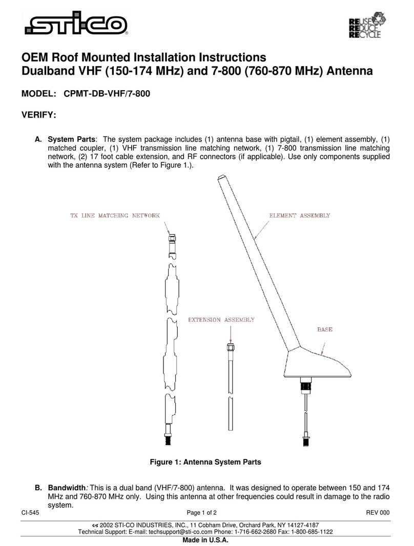
5. Connect the coupler to the antenna’s cable (pigtail). Connect the shrink tubed matching network to the
VHF port on the coupler. Connect one of the 17 foot cable extensions to the other end of the matching
network. Connect the other cable extension to the UHF port on the coupler. Trim any excess cable from
both cable extensions. Note: Do NOT overtighten the SMA connectors.
6. Conceal excess cabling under the headliner.
7. Test antenna before re-installing the vehicle’s trim. (See below)
Note: Take care not to tear the sheath of the cable when pulling through sharp body panels. If a hole appears in
the cable’s sheath, cover with several layers of a high quality electrical tape.
TESTING:
Installation testing, if required, must take place at the transmitter side of the feedline. This will ensure that the
cable connectors and cables have the proper continuity. Make sure all doors; hood, and trunk are closed.
A. Reflective Power: A measurement of reflective power using a wattmeter, you can expect up to 11%
reflected power. When results are greater than 11%, recheck the grounding.
B. SWR: A measurement of SWR (standing wave ratio) will yield better than 2:1. If greater than 2:1,
recheck the grounding.
Note: Some vehicles are sensitive to VHF frequencies. STI-CO suggests that you isolate the
transmission line and check for unwanted interference with the ignition switch on.

