3
1. Operating instructions for users and contractors
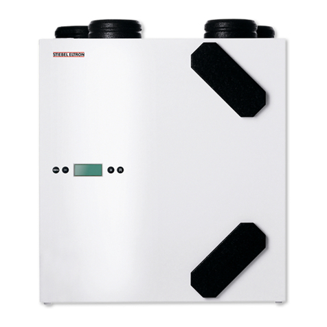
1.1 Equipment description
1.1.1 General
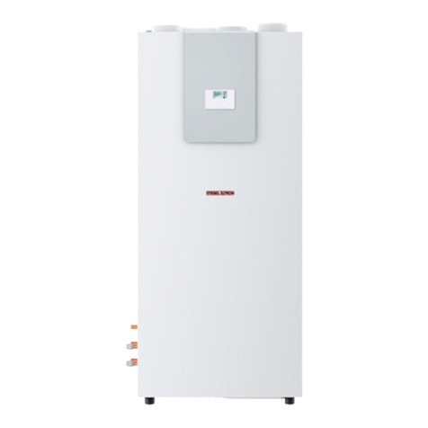
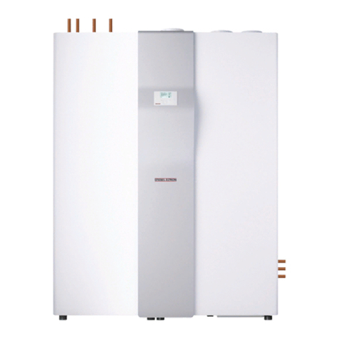
The LWZ 170/270..plus can recover up to
90 % of the latent energy in extract air.This
is made possible by the use of new types of
countercurrent heat exchangers.The air flow
rate is regulated independently by two energy-
saving DC fans.This makes the LWZ 170/270..
plus a particularly powerful and highly efficient
central unit for ventilating several rooms.
The plus version is equipped with an integral
bypass damper that channels cool ventilation
air into rooms on hot summer nights.
1.1.2 Description of functions
A central control unit safeguards the reliable
equipment operation and minimum energy
consumption whilst maintaining maximum
comfort. It ensures that the selected set air
flow rates remain constant.
The LWZ 170/270..plus is equipped with a
user interface with display.That enables an
infinitely variable adjustment of the air flow
rate as well as the scanning of operating details
on the display, without requiring the device to
be opened.
Settings in the program of the central
controller can be called up and modified at
the user interface.
At a glance
Switching the device ON and OFF
Displaying the fan stage and the
air flow rate
Infinitely variable flow rate selection
Scanning temperatures and status
Fault display
Optionally with integral bypass
(plus version)
1.1.3 Function
The LWZ 170/270 central ventilation unit
uses two fans and separate ducts to draw,
respectively via individual filter mats, outside
air into the building and extract air from
rooms that are subject to odour or humidity
loads (kitchen, bathroom, toilet, conservatory).
Both air streams are routed via a
countercurrent heat exchanger where the
outside air absorbs energy that is transferred
from the extract air.The airways are separated
from each other, thereby preventing odours
from being transferred between outside
air and extract air, subject to the correct
operation of the equipment.
The heated fresh air is blown into the
accommodation via suitable air ducts and
adjustable vents (available as accessories),
whilst the cooled extract air is expelled
through the roof or through a wall.
1.1.4 Shutting the equipment down
Even during longer periods away from home,
it is recommended that the equipment should
be allowed, via the remote control, to run
at switch position 1. Should the equipment,
nevertheless, be switched off for longer
periods, pull its power supply plug from the
socket. Prior to this disconnection, switch OFF
the device via the user interface.
1.1.5 Incorrect operation
Never
use extract air loaded with grease, explosive
gases, dust or adhesive aerosols
install the unit outdoors
connect cooker hoods and dryer exhausts
to the ventilation system.
Only qualified contractors are permitted to
work on the equipment. Never adjust the
ventilation and extract air valves inside the
rooms.These have been adjusted during
commissioning. Never make any modifications
to the internal equipment electrics or controls.
Trouble-free operation can only be ensured
with a closed filter door.
–
–
–
1.1.6 Regulations and standards
DIN 18017 - Ventilation of bathrooms and
flush toilets
DIN 1946 T6 E - Ventilation and air
conditioning, domestic ventilation
DIN 2088 - Domestic ventilation equipment
VDI 2087 - Air ducts [or local regulations]
Relevant Building Regulations
Important information
Please note:The ventilation device
must only be installed and
maintained by qualied contractors.
Operating and installation
instructions
Note: Keep these operating and
installation instructions safely and
pass them on to any new user, should the
equipment change hands, and let your
contractor check their content in
conjunction with any maintenance and
repair work.
Function diagram
Outside air / ventilation air
Extract air / expelled air
Connector
Room air temperature sensor
Countercurrent heat exchanger
Extract air filter
Outside air filter
Outside air temperature sensor
Condensate drain connection
Extractor fan
User interface
Control PCB
Outside air fan
Cable entries
1
2
3
4
5
6
7
8
9
10
11
12
12
7
1
2
3
4
5
6
11
10
9
8
C26_04_01_0190

