OPERATION
SAFETY
ENGLISH
WWW.STIEBEL-ELTRON.COM WPL 10 ACS | 5
2. Safety
2.1 Intended use
The appliance is designed for the following purposes:
- For central heating
- For central cooling
- For DHW heating
Observe the operating limits listed in chapter “Specification”.
This appliance is designed for domestic use. It can be used safely
by untrained persons. The appliance can also be used in a non-
domestic environment, e.g. in a small business, as long as it is
used in the same way.
Any other use beyond that described shall be deemed inappropri-
ate. Observation of these instructions and of instructions for any
accessories used is also part of the correct use of this appliance.
Any changes or conversions to the appliance void any warranty.
2.2 Safety instructions
Observe the following safety instructions and regulations.
- The electrical installation and installation of the heating cir-
cuit must only be carried out by a qualified contractor or by
our customer service engineers.
- Contractors are responsible for adherence to all currently ap-
plicable regulations during installation and commissioning.
- Operate the appliance only when fully installed and with all
safety equipment fitted.
- Protect the appliance from dust and dirt ingress during
building work.
!
WARNING Injury
The appliance may be used by children aged 8 and up
and persons with reduced physical, sensory or mental
capabilities or a lack of experience provided that they
are supervised or they have been instructed on how to
use the appliance safely and have understood the result-
ing risks. Children must never play with the appliance.
Children must never clean the appliance or perform user
maintenance unless they are supervised.
2.3 CE designation
The CE designation shows that the appliance meets all essential
requirements according to the:
- Electromagnetic Compatibility Directive
- Low Voltage Directive
3. Equipment description
3.1 Properties
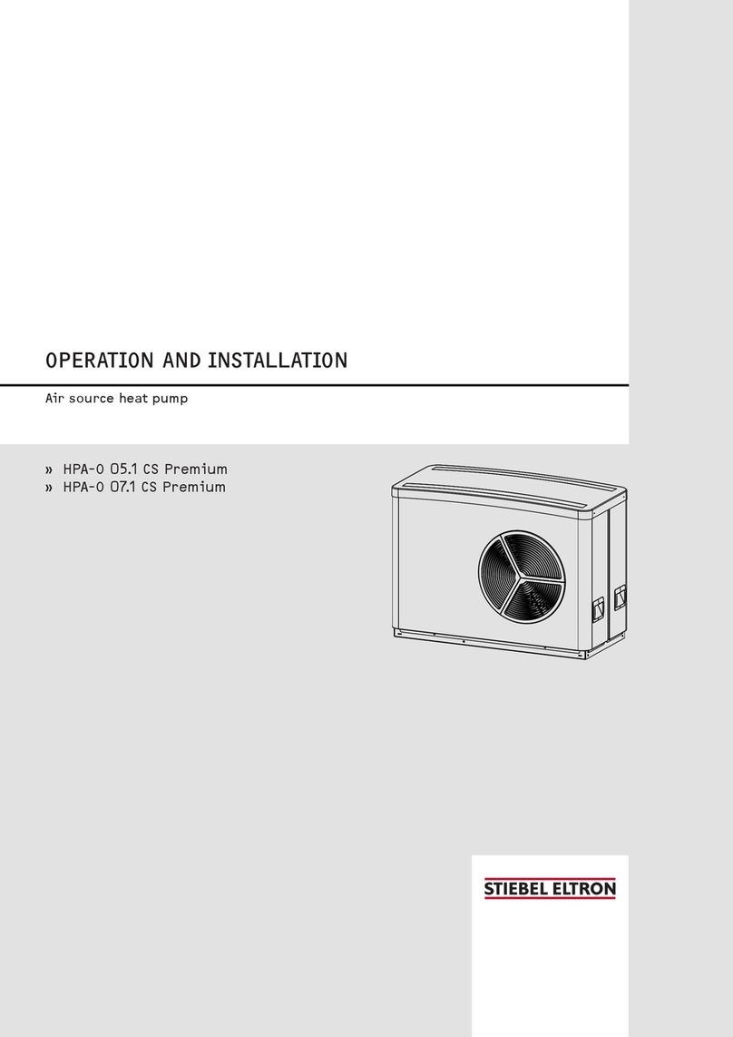
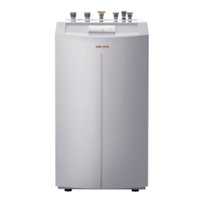
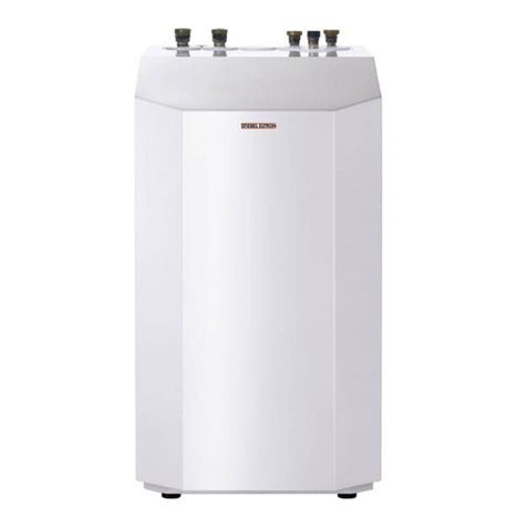
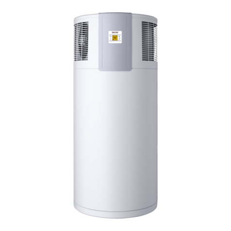
The appliance is an air source heat pump for external installation
that is designed to provide central heating. Heat is extracted from
the outside air at a low temperature level, and is then transferred
to the heating water at a higher level. The heating water can be
heated up to a flow temperature of 60 °C. The refrigerant circuit
is reversed for cooling operation.
The appliance is equipped with an electric emergency/booster
heater (DHC). In mono mode, the electric emergency/booster
heater is activated when the dual mode point can no longer be
maintained, in order to safeguard heating operation and to pro-
vide high DHW temperatures. In such cases, the electric emer-
gency/booster heater is activated in mono energetic operation as
a booster heater.
This appliance has further operational characteristics:
- Suitable for underfloor and radiator heating.
- Preferred for low temperature heating systems.
- Still extracts heat from the outside air at -20 °C outside
temperature.
- Corrosion-protected, external casing made from galvanised
sheet steel plus stove-enamelled finish.
- Comprises all components required for operation and all
safety equipment.
- Filled with non-combustible safety refrigerant.
- Suitable for cooling through extraction of heat from the heat-
ing system.
Note
For centralised control over the entire heating system,
you would need the “WPM 3” heat pump manager.
3.2 Function
Heat is extracted from the outdoor air via the heat exchanger
(evaporator) on the air side. The evaporated refrigerant is com-
pressed by a compressor. Electrical energy is necessary for this
process. At this point, the refrigerant is at a higher temperature
level. A further heat exchanger (condenser) transfers the heat to
the heating circuit. During this process, the refrigerant expands
again, and the cycle begins again.
During cooling mode, the condenser becomes the evaporator and
the evaporator becomes the condenser. The cycle is reversed. This
enables heat to be transferred from the internal rooms to the
outdoor air.
At air temperatures below approx. +7 °C, the humidity in the air
condenses as hoarfrost on the evaporator fins. Any hoarfrost is
automatically defrosted. Water created by this process collects in
the defrost pan and is drained off via a hose.
!
Damage to the appliance and the environment
In the defrost cycle, the fan is switched off and the heat
pump circuit is reversed. The heat required for defrosting
is drawn from the buffer cylinder. For operation without
a buffer cylinder, the general conditions defined in the
chapter “Installation without buffer cylinder” must be
adhered to. Otherwise the heating water freezes under
unfavourable conditions.
The heat pump automatically reverts to heating mode at the end
of the defrost cycle.


