manuals.online logo
Brands
  1. Home
  2. •
  3. Brands
  4. •
  5. Carrier
  6. •
  7. Heat Pump
  8. •
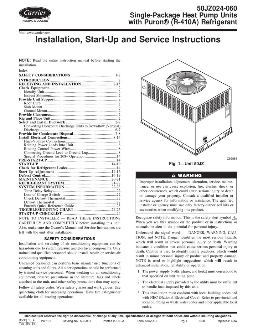
  9. Carrier 30ZQ024-G Installation manual

Carrier 30ZQ024-G Installation manual

Page 1
PLAN
VIEW
SIDE
ELEVATION
Wiring access
024 - as shown.
036 & 065, drill
holes & fit
grommets as
necessary.
water pipe
connections
direction
of air flow
600mm min, clearance
for service access.
TRANSPORT DAMAGE
As soon as the unit is delivered to site, check
for evidence of freight damage. If there is any
damage, file a claim with the transport
company immediately, and contact your
Carrier representative.
LOCATION OF UNIT
•Consult local building codes for any
special building requirements and noise
level limitations.
•Leave sufficient clearance around the unit
for service access and for proper air flow
through the unit.
•Avoid complaints from neighbours by
locating the unit away from neighbouring
structures such as windows or hard
surfaces that might reflect and amplify
noise.
WEATHER PROOF
Carrier Heat Pumps are completely weather
proof and are suitable for mounting indoors
(e.g. garages, etc) or outdoors.
MOUNTING
The unit should be mounted on a level base,
ideally a concrete slab, or equivalent
structure.
INDOOR INSTALLATION
When mounted indoors, the Heat Pump outlet
should exhaust to outside and have a 600mm
minimum clearance on the side indicated
below, for service access. The Heat Pump
needs to draw air from inside the room, so
ensure there is some means for the air to
seep in. (wall grille, door grille, etc..)
SWIMMING POOL HEAT PUMP
world leader in air
conditioning and
heating
technology
Installation &
Startup
Instructions
30ZQ024-G
30ZQ036
30ZQ065
30ZQ036
Page 2
150mm
150mm
Avoid exhaust air
recirculating back into
the air intake
PLAN
Model 30ZQ024-G 30ZQ036 30ZQ065
Voltage 220 - 240V 220 - 240V 380 - 415V
Run Amps 10.5A 18A 11A/ph
Fuse (HRC or CB) 20A 30A 20A/ph
Height (mm) 815 1215 1215
Width (mm) 800 1180 1180
Depth (mm) 300 500 500
Weight (kg) 65 207 230
Pipe sizes (mm) 40 40 40
Nominal flow (l/s) 2.5 2.9 5.8
OUTDOOR INSTALLATION
The unit should be located away from
sources of dust, leaves, debris or other loose
material that may drift into and obstruct the
air intake.
SITING
The unit and its associated isolating switch
must be installed no closer than 3.0m from
the end of the pool.
SUN HEAT
Unlike solar panels, Heat Pumps are not
dependent on sunlight for proper operation.
The Heat Pump will operate efficiently
whether in sunlight or shade.
VENTILATION
Enough room should be allowed around the
unit for proper air flow to the air intake. Cold
'exhaust' air should not be allowed to short
circuit back into the air intake.
PIPING
The Heat Pump has standard 40mm PVC
pipe connections. Pipe to the Heat Pump
upstream of the filter assembly to ensure only
filtered water goes through the heat
exchangers. Where a salt water chlorinator is
installed, re-pipe the chlorinator after the Heat
Pump. Use mack unions for connection to
the Heat Pump.
WIRING (see back page for connection diagrams)
The electrical connection to the Heat Pump
must comply with the local supply authority's
requirements and wiring regulations. Typical
requirements are as follows;
•A weather proof (IPX4) motor-rated
switch must be installed adjacent to the
Heat Pump and no closer than 3.0m from
the edge of the pool.
•The electrical wiring protection must be
rated for the motor starting current.
•Electrical and controls cabling to the Heat
Pump should be routed through the
internal conduit provided to avoid wire
contact with hot pipes connected to the
compressor.
TECHNICAL SPECIFICATIONS
START UP PROCEDURE
1. Read the Installation and Operating
Instructions carefully.
2. Ensure the location and siting of the Heat
Pump allows unrestricted air flow to and
from the unit.
3. Avoid short circuiting air flow from the air
discharge (exhaust) back into the air
intake.
4. Ensure the Heat Pump is level.
5. Ensure all circuit breakers, fuses, cabling
and circuits are of the correct sizes and
type for the application.
6. Pre-set the thermostat to 28oC (for pools
& 38oC for spas).
7. Switch on the main isolator to the Heat
Pump, and turn on control switch. (RED
light glows)
8. Start the circulating pump.
9. The Heat Pump will automatically start up
when the water pressure reaches its
setpoint. The AMBER light will glow and
the thermostat will indicate the current
water temperature.
10. Ensure that the water pressure switch
shuts off the Heat Pump when the
circulating pump stops.
Page 3
SETTING UP THE HEAT PUMP
1. WATER PRESSURE SWITCH
The water pressure switch senses when the
circulating pump is running and ensures there
is water flow before the Heat Pump starts. It
is factory set to start the Heat Pump when the
water pressure reaches 35 kPa and stops it
when it falls below 20 kPa. The water
pressure switch (which is located close to
where the refrigerant pipes enter the heat
exchanger), is adjustable.
If the pressure is too low to activate the water
pressure switch (AMBER light glows),
proceed as follows :-
1. Check filter condition and clean or
backwash if required.
2. Check for blocked lint pot or skimmer box.
3. Disconnect any pool accessories, such as
pool vacuums, that may be hindering
flow.
4. With the Heat Pump switched off, lower
the pressure switch setting and listen for
a distinct 'click' as the circulating pump
starts and stops.
5. If the Heat Pump is located lower than the
water level of the pool, the 'head' of pool
water may be sufficient to hold the water
pressure switch in the ON position.
Adjust the water pressure switch setting
to avoid this happening.
6. If the water flow into the pool is
unrestricted (open pipe or without jets), a
restrictor or tamper-proof valve needs to
be installed to increase the water
pressure to around 50 kPa.
2. WATER TEMPERATURE CONTROL
The controller displays the temperature of the
water entering the Heat Pump. Adjust the
thermostat to approximately 28oC. Press
'SEL' to display the current setpoint then
adjust with the up and down arrows. Press
'SEL' again to set the desired temperature.
3. SIGNAL LAMPS
Both the red and amber lights must be on
before the Heat Pump will start. Each light
indicates the following :-
•RED - glows when the Heat Pumps'
control switch has been turned on and
there is power to the unit.
•AMBER - glows when the circulating
pump is running and the water pressure
switch has closed. (I.e. there is sufficient
water flowing).
REFRIGERANT PRESSURE SWITCHES
The Heat Pump has other safety devices
which may prevent the unit from operating
while a non-critical fault exists. These are the
refrigerant high pressure and low pressure
cut-out switches.
If both the red and amber lights are on, and
the Heat Pump fails to start, switch off the
control switch and the power supply, then
turn both back on. This should re-set both
high and low pressure switches. The Heat
Pump should start again.
If after a brief period of 2 to 15 minutes, it
stops again, check that there is sufficient
water flow and that there are no blockages in
the pipes.
If the water flow is high, check the unit again
after 10 minutes.
If the unit stops again, turn off the power and
call your Carrier representative or the
company you purchased the Heat Pump
from.
WARNING!
SALT CHLORINATORS
Excessive chlorine in the pool water,
compounded by variable heating and filtration
cycles, may increase corrosion in the heat
exchanger material. Monitor the chlorine
levels in the pool regularly (daily is
recommended) to keep it within safe limits.
Also, maintain the pool within the water
temperatures recommended in the Owner's
Manual.
Page 4
P
N
E
FIELD WIRING
30ZQ024-G
phase
neutral
earth
L1
L2
E
FIELD WIRING
30ZQ036
phase
neutral
earth
L1
L2
L3
FIELD WIRING
30ZQ065
phase
phase
phase
Eearth
ELECTRICAL CONNECTIONS
CONTROLLER
DISPLAY
The controller displays the temperature of the
water entering the heat pump, which is also
the temperature of the pool.
SET POINT
The set point temperature is the pool
temperature that the heat pump will aim for
and maintain. To view the current set point
temperature, press the 'SEL' key.
To change the current set point temperature,
press 'SEL' then use the and the keys to
change the temperature setting. To complete
setting the temperature, press 'SEL' again.
NOTE
1. For servicing, use R22 refrigerant only.
2. The thermostat has a 10 second delay
from time of switching.
3. The compressor has a 1 to 5 minute time
delay. The fan starts before the
compressor.
Specification may change without notice.
Carrier Air Conditioning (NZ) Limited
25 Springs Rd
East Tamaki
Auckland, NEW ZEALAND
Private Bag 92-128, Auckland
Ph (64-9) 274-1390
Fax (64-9) 274-1380
Carrier Air Conditioning Pty Ltd
120-122 Terry St
Rozelle, NSW 2039
AUSTRALIA
Ph (61-2) 818-9700
Fax (61-2) 810-2963
PRG
mute
SEL
reverse direct

This manual suits for next models

2

Other Carrier Heat Pump manuals

Carrier 38AKS013-024 Manual

Carrier

Carrier 38AKS013-024 Manual

Carrier Performance 50VR-A User manual

Carrier

Carrier Performance 50VR-A User manual

Carrier 25HPA6 Quick start guide

Carrier

Carrier 25HPA6 Quick start guide

Carrier 50JS Assembly Instructions

Carrier

Carrier 50JS Assembly Instructions

Carrier 50HCQ04---12 Installation and user guide

Carrier

Carrier 50HCQ04---12 Installation and user guide

Carrier COMFORT 50EZ-A User manual

Carrier

Carrier COMFORT 50EZ-A User manual

Carrier PH14 B Series User manual

Carrier

Carrier PH14 B Series User manual

Carrier 38CQ Manual

Carrier

Carrier 38CQ Manual

Carrier 50JZ 024-060 Dimensions and installation guide

Carrier

Carrier 50JZ 024-060 Dimensions and installation guide

Carrier 50YA Operation manual

Carrier

Carrier 50YA Operation manual

Carrier AquaForce PUREtec 61XWHLZE 03 User manual

Carrier

Carrier AquaForce PUREtec 61XWHLZE 03 User manual

Carrier Gemini 38AU 07 Series Dimensions and installation guide

Carrier

Carrier Gemini 38AU 07 Series Dimensions and installation guide

Carrier WeatherMaster 50HCQA05 Installation and user guide

Carrier

Carrier WeatherMaster 50HCQA05 Installation and user guide

Carrier 50ZH Series Operation manual

Carrier

Carrier 50ZH Series Operation manual

Carrier 50ZH Series Operation manual

Carrier

Carrier 50ZH Series Operation manual

Carrier 50PEC09-18 Aquazone Dimensions and installation guide

Carrier

Carrier 50PEC09-18 Aquazone Dimensions and installation guide

Carrier 38YCB User manual

Carrier

Carrier 38YCB User manual

Carrier 25HCA User manual

Carrier

Carrier 25HCA User manual

Carrier 48VT-B Instruction Manual

Carrier

Carrier 48VT-B Instruction Manual

Carrier 50ZH Series User manual

Carrier

Carrier 50ZH Series User manual

Carrier 50EQ Dimensions and installation guide

Carrier

Carrier 50EQ Dimensions and installation guide

Carrier AQUASNAP 30RB 017-040 A User manual

Carrier

Carrier AQUASNAP 30RB 017-040 A User manual

Carrier Aquazone 50PSW025 Dimensions and installation guide

Carrier

Carrier Aquazone 50PSW025 Dimensions and installation guide

Carrier 25HNB5 User manual

Carrier

Carrier 25HNB5 User manual
Popular Heat Pump manuals by other brands

Daikin Altherma 3 H HT F Series Installer's reference guide

Daikin

Daikin Altherma 3 H HT F Series Installer's reference guide

Altherma EDHQ011AA6V3 installation manual

Altherma

Altherma EDHQ011AA6V3 installation manual

Gebwell Aries user manual

Gebwell

Gebwell Aries user manual

Panasonic CS-KE36NKU specification

Panasonic

Panasonic CS-KE36NKU specification

ICP PH55 Series installation instructions

ICP

ICP PH55 Series installation instructions

Viessmann VITOCAL 300-A Installation and service instructions

Viessmann

Viessmann VITOCAL 300-A Installation and service instructions

Econergy HP Series user manual

Econergy

Econergy HP Series user manual

Mitsubishi Electric Mr.Slim PUHZ-SHW-HA installation manual

Mitsubishi Electric

Mitsubishi Electric Mr.Slim PUHZ-SHW-HA installation manual

ClimateMaster Tranquility 16 Compact Series Installation, operation & maintenance manual

ClimateMaster

ClimateMaster Tranquility 16 Compact Series Installation, operation & maintenance manual

ESP HT 9 KW Installation and user manual

ESP

ESP HT 9 KW Installation and user manual

Climer ECOFLEX TD EF04TD Installation and user manual

Climer

Climer ECOFLEX TD EF04TD Installation and user manual

Lennox HS24-141 Unit information

Lennox

Lennox HS24-141 Unit information

Trane WCY024G1 Installation, operation & maintenance manual

Trane

Trane WCY024G1 Installation, operation & maintenance manual

Daikin ETBX16DF6V Operation manual

Daikin

Daikin ETBX16DF6V Operation manual

Crystal Crystal Horizontal 70 Installation and user manual

Crystal

Crystal Crystal Horizontal 70 Installation and user manual

Mitsubishi Electric TRANE TPKA0A 1LA00 Series Operation manual

Mitsubishi Electric

Mitsubishi Electric TRANE TPKA0A 1LA00 Series Operation manual

Mitsubishi Electric TPKA0A 1KA Series installation manual

Mitsubishi Electric

Mitsubishi Electric TPKA0A 1KA Series installation manual

Panasonic WH-SXC09F9E8 Service manual

Panasonic

Panasonic WH-SXC09F9E8 Service manual

manuals.online logo
manuals.online logoBrands
  • About & Mission
  • Contact us
  • Privacy Policy
  • Terms and Conditions

Copyright 2025 Manuals.Online. All Rights Reserved.