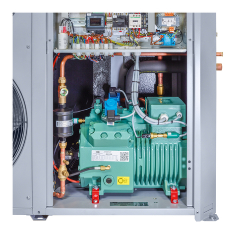
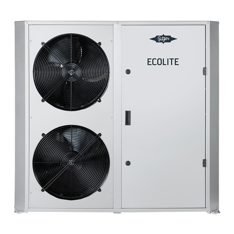
Bitzer ECOSTAR LHV6/2DC-3.F1Y User manual

* Hinweis gilt nur für Länder der EU * Information is valid for countries of the EC * 情報は EU 諸国に有効
Betriebsanleitung
Operating Instructions
取扱説明書
Ecostar
®
– Air-cooled
condensing units with
frequency regulated
Octagon
®
compressors
• LHV6/2DC-3.F1(Y)
• LHV6/4FC-5.F1(Y)
• LHV6/4EC-6.F1(Y)
Content Page
1 Safety 1
2 Classification according to EC
directives 4
3 Application ranges 6
4 Plant design 6
5 Mounting 7
6 Electrical connection 10
7 Commissioning 10
8 Operation / Maintenance 11
9 De-commissioning 12
1 Safety
These refrigeration condensing units
are intended for installation in machines
according to the EC Machines
Directive 2006/42/EC. They may be put
to service only, if they have been
installed in these machines according to
the existing Assembly/Operating
Instructions and as a whole agree with
the corresponding provisions of
legislation (standards to apply: refer to
Declaration of Manufacturer/of
Incorporation).* The electrical
components are in accordance with the
EC Low Voltage Directive 2006/95/EC.
For the pressure-bearing components
the EC Pressure Equipment Directive
97/23/EC (PED) may be additionally
applied. See also chapter 2.
Ecostar
®
–周波数制御式
Octagon
®
コンプレッサー付き
空冷コンデンシングユニット
• LHV6/2DC-3.F1(Y)
• LHV6/4FC-5.F1(Y)
• LHV6/4EC-6.F1(Y)
目次 ページ
1 安全性について 1
2 EC指令準拠の分類 4
3 適用範囲 6
4 システム構成 6
5 取付け 7
6 電気接続 10
7 試運転 10
8 運転/メンテナンス 11
9 稼動停止 12
1 安全性について
これらの冷凍コンデンシングユニットは、
EC機械指令2006/42/ECに準拠した機械へ
の取付けを前提としています。
上記のコンプレッサーが付属の組立/取扱説
明書に従って機械に取り付けられ、全体が
関係法規/規格を満たしている場合にのみ、
コンプレッサーを稼働させることができま
す(関係規格については、メーカー/サプラ
イヤーから提供される関係資料を参照して
ください)。*電気コンポーネントはEC低電
圧指令2006/95/ECに準拠しています。
さらに、加圧コンポーネントについてはEC
圧力機器指令97/23/EC(PED)が適用され
ます。2章も参照してください。

2 KB-201-2
Authorized staff
All work on compressors and
refrigeration systems shall be carried
out by qualified and authorized
refrigeration personnel only.
認定された専門技術者
コンプレッサーと冷凍システムに関わる
すべての作業は、有資格の認定された冷
媒取扱作業者が行ってください。
The condensing units are constructed
according to the state of the art and valid
regulations. Particular emphasis has
been placed on the users' safety.
Retain these Operating Instructions
during the entire lifetime of the
condensing unit.
Supplementary Instructions
In addition to these Instructions the
Operating Instructions for the
compressor and the pressure vessel
must be taken into consideration as well
(accompanying document to condensing
unit). This also applies for optional
accessories.
コンデンシングユニットは最新の有効な法
規に従って設計されており、特にユーザーの
安全を重視した構造になっています。
コンデンシングユニットの使用期間中は
取扱説明書を手元に大切に保管してくだ
さい。
補足的な指示
これらの指示に加えて、コンプレッサー
と圧力容器の取扱説明書もよく目を通
し、指示に従って作業してください(コ
ンデンシングユニットの付属文書)。こ
れはオプションアクセサリーにも当ては
まります。
See Technical Information KT-200
for detailled desciption of electrical
commissioning.
電気的な試運転の詳細について
は、技術資料KT-200を参照してく
ださい。
Residual hazards
Certain residual hazards from single
components of the condensing unit are
unavoidable.
A
ll persons working on this condensing
unit must therefore read these Operating
Instructions carefully!
A
ll of the following have validity:
• specific safety regulations and
standards (e. g. EN 378 and EN
60204),
• generally acknowledged safety
standards,
• EU directives,
• national regulations.
Safety references
are instructions intended to prevent
hazards.
Safety references must be stringently
observed!
危険性
コンデンシングユニットの個別コンポー
ネントの使用によって、避けることので
きない危険が生じる場合があります。
そのため、コンデンシングユニットに関
わる作業を行う前に必ずこれらの取扱説
明書をよくお読みください。
次に示すすべての法規・規則を遵守する
必要があります。
• 関係する安全規則および標準
(EN 378、EN 60204 など)
• 一般に認められている安全基準
• EU 指令
• 各国の規定
安全基準
安全基準は危険を防止するために設けら
れています。
安全のための注意事項は必ず遵守してく
ださい!
!
Attention!
Instructions on preventing possible
damage to equipment.
!
注意!
装置が損傷する危険を防止するた
めの指示です。
Caution!
Instructions on preventing a
possible minor hazard to persons.
警戒!
人に対する軽度の危険を防止する
ための指示です。

KB-201-2 3
Warning!
Instructions on preventing a
possible severe hazard to persons.
警告!
人に対する重度の危険を防止する
ための指示です。
Danger!
Instructions on preventing a
immediate risk of severe hazard to
persons.
危険!
人に対する直接的な重度の危険を
防止するための指示です。
General safety references 一般的な安全基準
Warning!
The condensing unit is under
pressure with a holding charge to a
pressure of 0.5 to 1 bar above
atmospheric pressure.
Incorrect handling may cause
injury to skin and eyes.
Wear safety goggles while working
on compressor!
Do not open connections before
pressure has been released.
警告!
コンデンシングユニットは充填ガ
スが封入された状態で納入されま
す(大気圧0.5~1bar)。
不適切に取り扱うと、皮膚や目に
けがを負うおそれがあります。
コンプレッサーに関わる作業を行
うときは、安全メガネを着用して
ください。
接続口を開く場合は、先に必ず圧
力を抜いてください。
Caution!
During operation surface
temperatures exceeding 60C or
below 0C can be reached.
Serious burns and frostbite are
possible.
Lock and mark accessible sectors.
Before working on the compressor
and pressure-bearing components:
Switch off the condensing unit and
allow to cool down.
警戒!
運転中は表面温度が60°C以上または
0°C以下になることがあります。
重度の火傷および凍傷の危険があり
ます。
危険なエリアに人が接近できないよ
うに施錠し、危険を示すマークを付
けてください。
コンプレッサーと加圧コンポーネン
トに関する作業を行う前に
コンデンシングユニットの電源を
切り、装置が冷えるまで待ってく
ださい。
For any work on the condensing unit
after the plant has been commissioned
or charged with refrigerant:
プラントの試運転後または冷媒充填後
のコンデンシングユニットの作業につ
いて:
Warning!
Condensing unit is under pressure!
In case of improper handling severe
injuries are possible.
Release the pressure in the
compressor!
Wear safety goggles!
警告!
コンデンシングユニットには内圧が
かかっています。
不適切に取り扱うと、重度のけがを
負うおそれがあります。
コンプレッサー内の圧力を抜いてく
ださい。
安全メガネを着用してください。
For any work on rotating parts
additionally:
回転部品に関する作業について:
Danger!
Rotating parts!
In case of improper handling most
severe injuries possible.
Before removing the guard plates
and protection caps:
Switch off the condensing unit and
remove the fuses!
危険!
回転部品!
不適切に取り扱うと、重度のけが
を負うおそれがあります。
ガードプレートと保護キャップを
取り外す前に:
コンデンシングユニットの電源を
切り、ヒューズを外してください。

4 KB-201-2
Rotating parts:
• Condenser fan (air cooling)
2 Classification of condensing units
and their components according to
EC directives
The condensing units are intended for
installation in machines according to the
EC Machines Directive 98/37/EC.
Electrical components are in
accordance with the EC Low Voltage
Directive 2006/95/EC. Additionally, the
EC Pressure Equipment Directive
97/23/EC (PED) may be applied for
pressure bearing components –
compressors are however an exception
(see below). The corresponding
Declaration of Conformity or
Manufacturer's Declarations are
available.
For the classification of individual
components and for additional
explanations see the table on page 14.
回転部品:
• コンデンサーファン(空冷)
2 EC 指令に準拠したコンデンシング
ユニットとコンポーネントの分類
コンデンシングユニットは、EC機械指
令98/37/ECに準拠した機械への取付け
を前提としています。電気コンポーネン
トはEC低電圧指令2006/95/ECに準拠し
ています。さらに、加圧コンポーネント
についてはEC圧力機器指令97/23/EC
(PED)が適用されます(ただしコンプ
レッサーを除く - 下記を参照)。該当
する適合性宣言と製造者宣言がありま
すので併せてご参照ください。
個別コンポーネントの分類とその他の説
明については14ページの表を参照して
ください。
Condensing units are not a
"functional whole" according to
PED and thus do not belong to the
scope of Art.1 § 2.1.5
"Assemblies". The directive is thus
only applied to individual
components. The same applies to
the CE Marking.
Assessment through notified body:
Bureau Veritas, Paris – "Technical
Appraisal" for ASERCOM
members
PED-TA_ASE_001_01-DEU.
コンデンシングユニットはPEDに
準拠した「機能的ユニット」では
ないため、第1章2.1.5節「アセンブ
リー」の範囲には含まれません。
そのため、この指令は個別コン
ポーネントにのみ適用されます。
CEマークについても同様です。
検査機関による評価:
Bureau Veritas、Paris –
ASERCOM会員用「技術評価」、
PED-TA_ASE_001_01-DEU
According to Art. 3 § 3.10
semi-hermetic and open drive
compressors are excluded from
the scope of the PED. This
exemption clause is confirmed by
a notified body.
For further explanations see
"Declaration on Product
Conformity" AP-100.
For the classification of
pressurised accessories for
compressors see AP-100.
第3章3.10節に基づき、半密閉型お
よび開放型コンプレッサーはPED
の適用範囲には含まれません。
この免責条項は検査機関によって
確認されています。
詳しくは「製品適合性宣言」AP-100
を参照してください。
コンプレッサー用加圧アクセサ
リーの分類についてはAP-100を参
照してください。

KB-201-2 5
Fig. 1 Schematic design of air-cooled
condensing units with frequency
regulated semi-hermetic Octagon
®
compressors - Ecostar
®
図1 周波数制御式半密閉型 Octagon
®
コンプ
レッサー付き空冷コンデンシングユニッ
ト- Ecostar
®
の構成図
Classification according the PED of the
numbered components see table on page
14.
* Only for LHV6/2DC-3.F1(Y)
PED に準拠した数字付きコンポーネント
の分類については 14 ページの表を参照し
てください。
*
LHV6/2DC
-
3.F1
(
Y
)用のみ
Einstufung der nummerierten Bauteile
ent-sprechend der PED siehe Tabelle
Seite 14.
* Nur für LHV6/2DC-3.F1(Y)

6 KB-201-2
2.1 State of delivery
Holding charge:
approx. 0.5 .. 1 bar above atmospheric
pressure
Technical Data see brochures of the
condensing units: KP-207.
3 Application ranges
A
pplication limits see brochures
2.1 納品状態
充填ガス:
大気圧より約 0.5~1 bar 高い
技術データはコンデンシングユニット
KP-207 のカタログを参照してください。
3 適用範囲
適用制限はカタログを参照してください。
Zulässige Kältemittel
Permitted refrigerants
使用が許可される冷媒
HFKW /HFC
R134a –R404A –R507A –R22 –R407C
Ölfüllung
Oil charge
充填オイル
t
c
< 55°C:
BITZER BSE32
Maximal zulässiger Druck (PS)
Maximum allowable pressure (PS)
最高許容圧力(PS)
28 bar
Further refrigerants upon request
For alternative oils see Technical
Information KT-500 and KT-510
• KP-100 (Semi-hermetic Reciprocating
Compressors)
• or BITZER Software.
4 Plant design
4.1 Place of installation
The place of installation must be a good
bearing soil and horizontally adjusted
(see also chapter 5).
Consider minimum and maximum load
for plant design. Design pipework and
rising pipes similar to common rules for
compound systems.
For operation under extreme conditions
(e. g. aggressive or corrosive
atmospheres, low ambient temperatures
etc.) consultation with BITZER is
recommended.
その他の冷媒はお問い合わせください。
代替オイルは技術資料 KT-500 および
KT-510 を参照してください。
• KP-100(半密閉型レシプロコンプレッ
サー)
• または BITZER ソフトウェア
4 システム構成
4.1 設置場所
機械は、十分な強度がある水平な地面に
設置してください(5章も参照)。
システム構成では最小負荷と最大負荷を
考慮してください。複合システム向けの
共通規則に従って配管し、上昇管を取り
付けてください。
過酷な条件下での運転時(例:厳しい環
境、腐食性の環境、低温の環境)には、
適切な措置を講じる必要がありますの
で、BITZER にぜひご相談ください。

KB-201-2 7
4.2 Maximum allowable pressure
The entire plant must be designed and
operated so that the maximum allowable
pressure (PS) cannot be exceeded in
any part of the plant (see name plate
indications).
Pressure relief valves are essential for
receivers and condensers (pressure
vessels) if
• it is to be expected that the maximum
allowable pressure will be exceeded
due to external heat sources (e.g.
fire), or if
• the entire refrigerant charge of the
plant is more than 90% of the receiver
volume of the pressure vessel at
20°(charge capacity). Receiver
volume means the volume between
operationally lockable valves before
and after a pressure vessel.
Safety switching device
In conformance with local regulations,
pressure limiting safety switching
devices must provided for.
5 Mounting
5.1 Condensing unit transport
Transport condensing unit either
screwed on a pallet or with vertical
tackle by using the eyebolts Ø 20
(option) (Fig. 2).
5.2 Compressor installation
The installation location must be
sufficiently stable and horizontal, and it
must also have sufficient space above it
(to ensure free air outlet of the fans).
The condensing unit can be installed in
three ways:
• The condensing unit is placed on
stable ground; it is mounted and
adjusted at its mounting feet (option).
• Without its mounting feet the
condensing unit is mounted onto
profiles (Fig. 3).
• Without its mounting feet the
condensing unit is mounted onto
consoles (not included in delivery)
attached to the wall.
4.2 最高許容圧力
全体的に、システムのいかなる部分でも
最高許容圧力(PS)を超えることのない
ように設計して運転する必要があります
(銘板の表示を参照)。
以下の場合はレシーバーとコンデンサー(圧
力容器)に圧力逃し弁が必要となります。
• 外部の熱源(火気など)のため、最高
許容圧力の超過が予想される場合
• システムの全冷媒充填量が 20°時の圧
力容器のレシーバー容量(充填容量)
の90%を超える場合。レシーバー容量
とは、圧力容器の前後にあるロック可
能なバルブに挟まれた空間の容積のこ
とです。
安全切換え装置
各国の法規に従い、圧力を制限する安全
切換え装置を取り付けてください。
5 取付け
5.1 コンデンシングユニットの搬送
コンデンシングユニットを搬送する場合
は、パレットにボルト固定するか、また
はØ 20のアイボルト(オプション)を使
用して垂直にチェーンで吊り上げてくだ
さい(図2)。
5.2 コンプレッサーの取付け
十分な強度のある水平面に設置してくだ
さい。また、上部に十分なスペースを設
けるようにしてください(ファンのエア
出口を確保するため)。コンデンシング
ユニットは3通りの方法で取り付けるこ
とができます。
• コンデンシングユニットを十分な強度
のある地面に配置し、取付け脚(オプ
ション)で固定・調整する
• 取付け脚を使用せず、コンデンシング
ユニットをプロファイル(図 3)上に
取り付ける
• 取付け脚を使用せず、コンデンシングユ
ニットを壁に取り付けたコンソール(納
品内容には含まれない)に取り付ける

8 KB-201-2
!
Attention!
When installed in areas where
extreme wind loads can occur
always mount condensing unit
without its feet tightly to the
ground!
!
注意!
風が極端に強いエリアに取り付け
る場合は、脚を使わずにコンデン
シングユニットを直接地面にしっ
かり固定してください。
!
Attention!
For rooftop installation ensure
sufficient lightning protection!
!
注意!
屋上に取り付ける場合は、十分な
避雷措置を講じてください。
Transport locks
When complete units are delivered the
anti-vibration mountings are locked to
prevent transport damages. These locks
must be removed resp. loosened after
installation. See the description in the
attached compressor Operating
Instructions.
Further detailed descriptions on
mounting see Operating Instructions of
the compressor, the pressure vessel
and if necessary of the optional
accessories.
5.3 Pipelines
搬送時の固定ロック
装置の納品時は振動防止具が取り付けら
れており、搬送時の損傷を防いでいます。
取付具は取付け後に外すか、もしくは緩め
る必要があります。添付のコンプレッサー
取扱説明書を参照してください。
取付けに関する詳細事項については、コ
ンプレッサー、圧力容器、必要に応じて
オプションアクセサリーの取扱説明書
を参照してください。
5.3 配管
!
Attention!
During braze work at suction line,
protect pressure transducer
against overheating (max. 120C)!
!
注意!
吸入配管をろう付けする場合、圧
力トランスデューサーを過熱から
保護してください(最高120°C)。
Fig. 2 Eyebolts (option) 図2 アイボルト(オプション)
Transportösen Ø 20 (Option)
Eyebolts Ø 20 (option)
Ø 20 のアイボルト(オプション)

KB-201-2 9
Fig. 3 Schematic view of bottom plate
Connections
図3 底板の概略図
接続
Transportösen Ø 20 (Option)
Eyebolts Ø 20 (option)
Ø 20 のアイボルト(オプション)
Montagefüβe Ø 80 (Option)
Mounting feet Ø 80 (option)
Ø 80 の取付け脚(オプション)
Anschluss-Positionen
1 Sauggas-Leitung*
2 Kältemittel-Austritt
3 Öffnung für Anschlusskabel
4 Schauglas
* detaillierte Informationen siehe
Betriebsanleitungen für
Druckbehälter
Connection positions
1 Suction gas line*
2 Refrigerant outlet
3 Opening for connection cable
4 Sight glass
* further detailed information on
mounting see Operating
Instructions of pressure vessels
接続位置
1 吸入ガス配管*
2 冷媒出口
3 接続ケーブル用開口部
4 サイトグラス
* 取付けに関する詳細については、
圧力容器の取扱説明書を参照して
ください。

10 KB-201-2
6 Electrical connection
Semi-hermetic compressors, condenser
fans and electrical accessories are in
accordance with the EC Low Voltage
Directive 2006/95/EC (CE 96).
6 電気接続
半密閉型コンプレッサー、コンデンサー
ファン、電気コンポーネントはEC低電圧
指令2006/95/EC(CE 96)に準拠してい
ます。
Danger!
High voltage until all capacitors are
discharged!
Make sure that the FI and all
secondary devices are voltage free
before opening the terminal box of
compressor or FI housing!
危険!
すべてのキャパシターが放電される
まで、高い電圧がかかっています。
FIとすべての二次装置に電圧がか
かっていない状態になってから、
コンプレッサーの端子ボックスま
たはFIハウジングを開けてください。
The electrical installation is to be carried
out according to the wiring diagram in
KT-200. Observe the safety standard
EN 60204 and national safety
regulations.
電気系統はKT-200の配線図に従って取
り付けてください。安全基準EN 60204
および各国の安全規定を遵守してくだ
さい。
!
Attention!
Protect controller from
overvoltage!
Use screened cables for the
connection of the options setpoint
adjustment, external release and
coldstore temperature sensor!
!
注意!
コントローラーを過電圧から保護
してください。
オプションの設定値調整、外部リ
リース、冷蔵温度センサーの接続
にはシールドケーブルを使用して
ください。
See Technical Information KT-200
for detailled desciption of electrical
commissioning.
電気的な試運転の詳細について
は、技術資料KT-200を参照してく
ださい。
7 Commissioning
Detailed description see Operating
Instructions KB-200 of the compressor:
• Leak testing
• Evacuation
• Refrigerant charging
• Checks before starting
• Start-up procedure
For switch-on proceed as described in
Technical Information KT-200.
7 試運転
詳細については、コンプレッサーの取扱
説明書KB-200を参照してください。
• 漏れテスト
• 真空引き
• 冷媒の充填
• 起動前の点検
• 起動手順
スイッチオン手順については、技術資料
KT-200を参照してください。

KB-201-2 11
7.1 Check oil level
During commissioning check oil level
under minimum load and maximum load
conditions (25 resp. 30/87 Hz). Repeat
check after several days of operation. If
the oil level permanently stays under 1/4
height of sight glass, the respective
amount of oil must be refilled. Record
the amount of refilled oil and provide it
on site.
For critical applications use optical oil
level monitoring OLC-K1 (see KT-180
and KT-200). Please contact BITZER.
8 Operation / Maintenance
8.1 Regular checks
The condensing unit must be regularly
inspected by authorized personnel. The
inspection intervals depend on
refrigerant, cooling agent and mode of
operation. They must be determined by
the end user.
Check also the operating data:
• Oil level of compressor
• Evaporating temperature
• Suction gas temperature
• Condensing temperature
• Difference between condensing
temperature and air admission
temperature into the condenser
• Discharge gas temperature
• Oil temperature
• Switching frequency
• Power consumption of the compressor
• Power consumption of the condenser
fan(s)
• Visually check cables and electrical
connections
Update data protocol and compare data
with previous measurements. In the
case of greater deviations, determine
the source of the problem and correct it.
Also check the following points and
maintain if necessary:
• Clogging of the condenser
• Refrigerant charge (condition in liquid
sight glass)
• Degree of moisture in refrigerant
(moisture indicator) – if necessary
replace dryer
7.1 オイルレベルの点検
試運転中に最小および最大の負荷条件
下で(25または30/87 Hz)オイルレベル
を点検し、数日後に再度点検してくださ
い。オイルレベルが常にサイトグラスの
1/4の高さより下にある場合には、不足
するオイル量を補充してください。ま
た、補充したオイル量を記録し、現場に
その量を用意しておいてください。
厳しい条件下で使用する場合は、オプショ
ンのオイルレベルモニターOLC-K1を使
用してください(KT-180とKT-200を参
照)。BITZERにお問い合わせください。
8 運転/メンテナンス
8.1 定期点検
コンデンシングユニットは認定技術者
による定期的な点検を受ける必要があ
ります。点検間隔は冷媒、冷却剤、運転
方法によって異なりますので、使用者が
その時期を決定してください。
運転データも点検してください。
• コンプレッサーのオイルレベル
• 蒸発温度
• 吸入ガス温度
• 凝縮温度
• 凝縮温度とコンデンサーへの吸気温度
の差
• 吐出ガス温度
• 油温
• 切換え頻度
• コンプレッサーの消費電力
• コンデンサーファンの消費電力
• ケーブルと電気接続の目視点検
データプロトコルを更新してデータと
以前の測定値と比較し、差が大きい場合
にはその問題の原因を突き止めてから
修正してください。
以下の項目も点検し、必要に応じて整備を
行ってください。
• コンデンサーの詰まり
• 冷媒充填量(液サイトグラスの状態)
• 冷媒の水分含量(モイスチャーインジ
ケーター)– 必要に応じて

12 KB-201-2
• safety-relevant parts e. g. pressure
limiters, motor protection device
For oil change and further maintenance
work see Operating Instructions for
compressors and pressure vessels.
• 圧力リミッター、モーター保護デバイ
スなどの安全関連部品
オイル充填とその他のメンテナンス作
業については、コンプレッサーと圧力容
器の取扱説明書を参照してください。
In case of frequency inverter
failure bypass operation is
possible with emergency service
cable (see also KT-200, chapter
6.4).
Please contact BITZER.
周波数インバーターが故障している
場合は、緊急サービスケーブルを使
用したバイパス運転を行うことがで
きます(KT-200の6.4章も参照)。
BITZERにお問い合わせください。
9 De-commissioning
9.1 Standstill
Keep the compressor crankcase heater
switched on until dismantling the
compressor. This prevents increased
refrigerant solution in the compressor oil.
9.2 Disassembling the condensing
unit or dismantling components
In case of disassembling, dismantling or
replacement of electrical or
pressure-bearing components:
9 稼動停止
9.1 停止
コンプレッサーを取り外すまで、コンプ
レッサーのクランクケースヒーターはオ
ンにしておいてください。これはコンプ
レッサーオイルへの冷媒の混入を防ぐた
めの措置です。
9.2 コンデンシングユニットまたはコン
ポーネントの取外し
電気部品または加圧部品の分解/取外し/
交換の場合:
Warning!
Electrical components may be live!
Severe injuries are possible.
Disconnect supply voltage!
Remove fuses!
警告!
電気コンポーネントに電圧がか
かっている場合があります。
重傷を負う危険があります。
電源を切り離してください。
ヒューズを外してください。
Warning!
Compressor and other
components can be under
pressure!
Severe injuries possible.
Release the pressure first!
Wear safety goggles!
警告!
コンプレッサーとその他のコン
ポーネントに内圧がかかっている
場合があります。
重傷を負う危険があります。
まず圧力を抜いてください。
安全メガネを着用してください。
Extracting refrigerant
Close the shut-off valve before and
behind the component. Pump-off or
suck-off the refrigerant and dispose of
properly!
冷媒の抜き取り
コンポーネントの前後にあるシャット
オフバルブを閉じます。冷媒をポンプで
排出するか、もしくは吸引し、適切に廃
棄してください。

KB-201-2 13
Draining the oil オイルの排出
Warning!
Oil temperature in compressor can
be above 60C after previous
operation.
Severe burnings possible.
Allow to cool down before
interventions!
警告!
コンプレッサー内の油温は、運転
後に60°C以上になっている場合が
あります。
重度の火傷を負う危険があります。
必ず冷えてから作業してください。
Disconnect supply voltage before
starting work and extract the refrigerant
– see above.
See compressor Operating Instructions
– oil change.
Dispose of the oil properly!
Chlorinated oil is pollutive waste.
Removing or disposing of the
compressor and other components
Removing the refrigerant and the oil see
above.
Removing single components or the
whole condensing unit:
• Close open connections gas tight (e.
g. shut-off valves, flanges, screwed
joints).
• Remove heavy parts if necessary with
a hoisting equipment.
• Have it repaired or disposed properly.
電源を切り離してから作業を開始し、冷
媒を抜いてください –上記を参照。
コンプレッサーの取扱説明書 –オイル
交換を参照。
排油は環境保護規定に従って廃棄して
ください!
塩素処理されたオイルは特殊廃棄物です。
コンプレッサーとその他のコンポーネ
ントの取外しまたは廃棄処分
冷媒とオイルの抜き取りは上記を参照
してください。
コンデンシングユニットの個別コンポーネ
ントまたはコンデンシングユニット全体の
取外し:
• 開いている接続口をガス漏れがない
ように閉じます(シャットオフバル
ブ、フランジ、ねじ込み継手など)。
• 重い部品は、必要に応じて吊り上げ具
を使用して取り外します。
• 取り外した部品を修理するか、または
適切に処分します。

14 KB-201-2
Classification of components to EC
directives
EC指令準拠のコンポーネントの分類
Bauteil Component コンポーネント Lieferumfang
Extend of delivery
納品範囲
標準装備
オプション
1 Verdichter halbhermetisch Compressor
semi-hermetic
半密閉型コンプレッサー
1a Druck-Absperrventil Discharge shut-off valve 吐出シャットオフバルブ
1b Saug-Absperrventil Suction shut-off valve 吸入シャットオフバルブ
2 Verflüssiger, luftgekühlt Condenser, air-cooled コンデンサー、空冷式
2a Verflüssiger-Lüfter Condenser fan コンデンサーファン
3 Kondensat-Leitung
Rohrverbindungen
Condensate line
Pipe joints
凝縮ライン
配管ジョイント
3a Hochdruck-Transmitter High pressure transmitter 高圧トランスミッター
4 Flüssigkeitssammler Liquid receiver 液レシーバー
4a Flüssigk.-Absperrventil Liquid shut-off valve 液シャットオフバルブ
5 Frequenzumrichter Frequency inverter 周波数インバーター
5a Anschlusskasten des
Verflüssigungssatzes
Terminal box of the unit ユニットの端子ボックス
6 Druckleitung
Rohrverbindungen
Discharge line
Pipe joints
吐出側配管
配管ジョイント
7 Pulsationsdämpfer Pulsation muffler 脈動マフラー
8 Druckgas-Temperaturfühle
r
Discharge gas
temperature sensor
吐出ガス温度センサー
10 Flüssigkeits-Leitung
Rohrverbindungen
Liquid line Pipe joints 液ライン 配管ジョイント
11 Filtertrockner Filter drier フィルタードライヤー
12 Schauglas Sight glass サイトグラス
13 Saugleitung
Rohrverbindungen
Suction line Pipe joints 吸入側配管 配管ジョイント
13a Niederdruck-Transmitter Low pressure transmitter 低圧トランスミッター
18 Druckwächter für
steigenden Druck
Pressure limiter for high
pressure protection
高圧保護用圧力リミッター
21 Verbindungsleitung
Druckwächter
Control line pressure
limiter
圧力リミッター接続ライン

KB-201-2 15
Fluid group 2 according PED
(refrigerant group L1 / EN 378).
Maximum allowable pressure PS:
28 bar (HP), 19 bar (LP)
Receivers according to cat. II,
procedure according to Art. 3.1.2, CE
sign at receiver
PED 97/23/EC, MD 98/37/EC, LVD 73/23/EEC
フルードグループ 2、PED
(冷媒グループ L1/EN 378)準拠
最高許容圧力(PS):
28 bar(HP)、19 bar(LP)
カテゴリーII 準拠のレシーバー、
Art. 3.1.2 準拠の手順、レシーバーの
CE マーク
PED 97/23/EC、MD 98/37/EC、LVD 73/23/EEC
Anwendungsbereich
under the scope of
適用範囲
PED ①MD LVD EMV
Kategorie / カテゴリー
CE-Zeichen
CE Marking
CE マーク
Betriebsanleitung
Operating Instr.
取扱説明書
Bemerkungen
Comments
注釈
Zubehör siehe Erklärung AP-100
アクセサリーは宣言 AP-100 を参照
= / < DN 32/PS 28 bar
= / < DN 50 / PS 19 bar
= / < DN 32/PS 28 bar
< DN 32 / PS 28 bar
lösb.Verb./ detach.joint / 取外し可能なジョイント < DN32
dauerh.Verb./ perman.joint / 固定ジョイント
< 7.1~35.7 dm3/ PS 28 bar
= / < DN 32/PS 28 bar
entspr./ according to / 準拠
< 1.78 dm
3
/ PS 28 bar
= / < DN 32/PS 28 bar
lösb.Verb./ detach.joint / 取外し可能なジョイント < DN32
< 1.78 dm
3
/ PS 28 bar
< 1.78 dm
3
/ PS 28 bar
< DN 50 / PS 19 bar
lösb.Verb./ detach.joint / 取外し可能なジョイント < DN50

Ä
nderungen vorbehalten / Subject to change / 予告なく変更する場合があります。 09.09 80480201
株式会社 ビッツァー・ジャパン
〒560-0082 大阪府豊中市新千里東町 1-4-2
千里ライフサイエンスセンタービル 14F
TEL 06-6873-8555
FAX 06-6873-8556
www.bitzer.jp・info@bitzer.jp
Other manuals for ECOSTAR LHV6/2DC-3.F1Y
1
This manual suits for next models
2
Table of contents
Other Bitzer Heat Pump manuals
Popular Heat Pump manuals by other brands

Dimplex
Dimplex WI 65TU Installation and operating instruction

Beretta
Beretta Tivano Series Installation and operation manual

Omega
Omega VSHP SERIES Installation and operation manual

DeLonghi
DeLonghi Bran 0011M H Installation, operating & service instructions

ICE AIR
ICE AIR RSXC Operating and maintenance manual

Nibe
Nibe Fighter 2005 Service instruction