3
1.5 Important information
Heat pumps must only be installed
and maintained by qualified con-
tractors.
Heat pump types
The description of individual functions var-
ies between the different heat pump types.
Therefore different types of heat pump are
determined, which are identified as
HP type 1, 2 or 3.
HP type 1: (Not this Heat Pump)
Heat pump with flammable refrigerant and
without internal secondary heater.
Rotary selector position 1, 2, 3, 9, A or B.
(WPWE .. KW and WPL .. KW)
HP type 2:
Heat pumps with safety refrigerant and in-
ternal second HS (Heat Source).
Rotary selector position 1.
(WPF 5 (S), 7 (S), 10, 13)
HP type 3:
Heat pumps with safety refrigerant and ex-
ternal second HS (Heat Source).
Rotary selector position 9.
(WPF 5 (S), 7 (S), 10, 13)
Never ...
process media which are not ex-
pressly approved
heat liquids other than heating water
install the equipment
a) outside
b) in rooms at risk from frost
c) in wet areas, e.g. bathrooms
d) in rooms at risk from heavy dust
contamination
e) in areas, where there is a risk of
explosions
operate the equipment
a) outside the stated temperature
limits
b) without minimum circulation
volume at the heat source and
heat reduction side
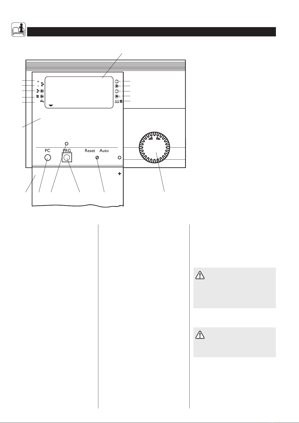
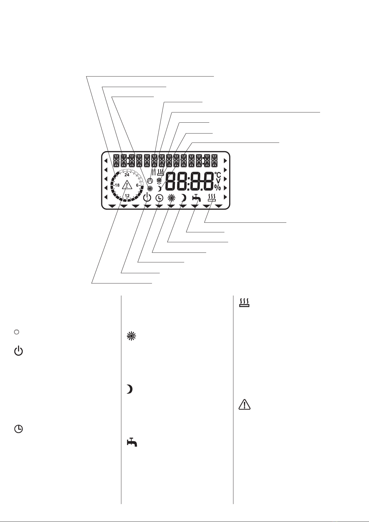
1.6 Operation
The operation is split over three control lev-
els. Control levels 1 and 2 are accessible to
users and contractors alike. Control level 3 is
only designed for qualified contractors:
Control level 1 (control flap closed)
This enables the adjustment of operating
modes, such as standby mode, programmed
operation, constant day or setback mode, etc.
(see section 1.8.1).
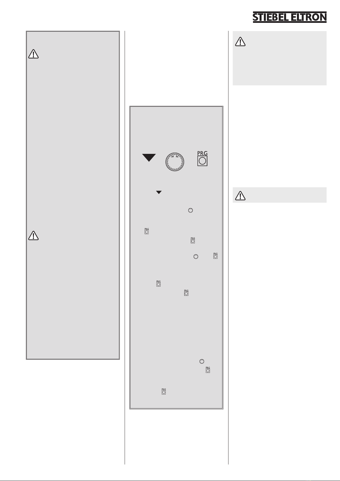
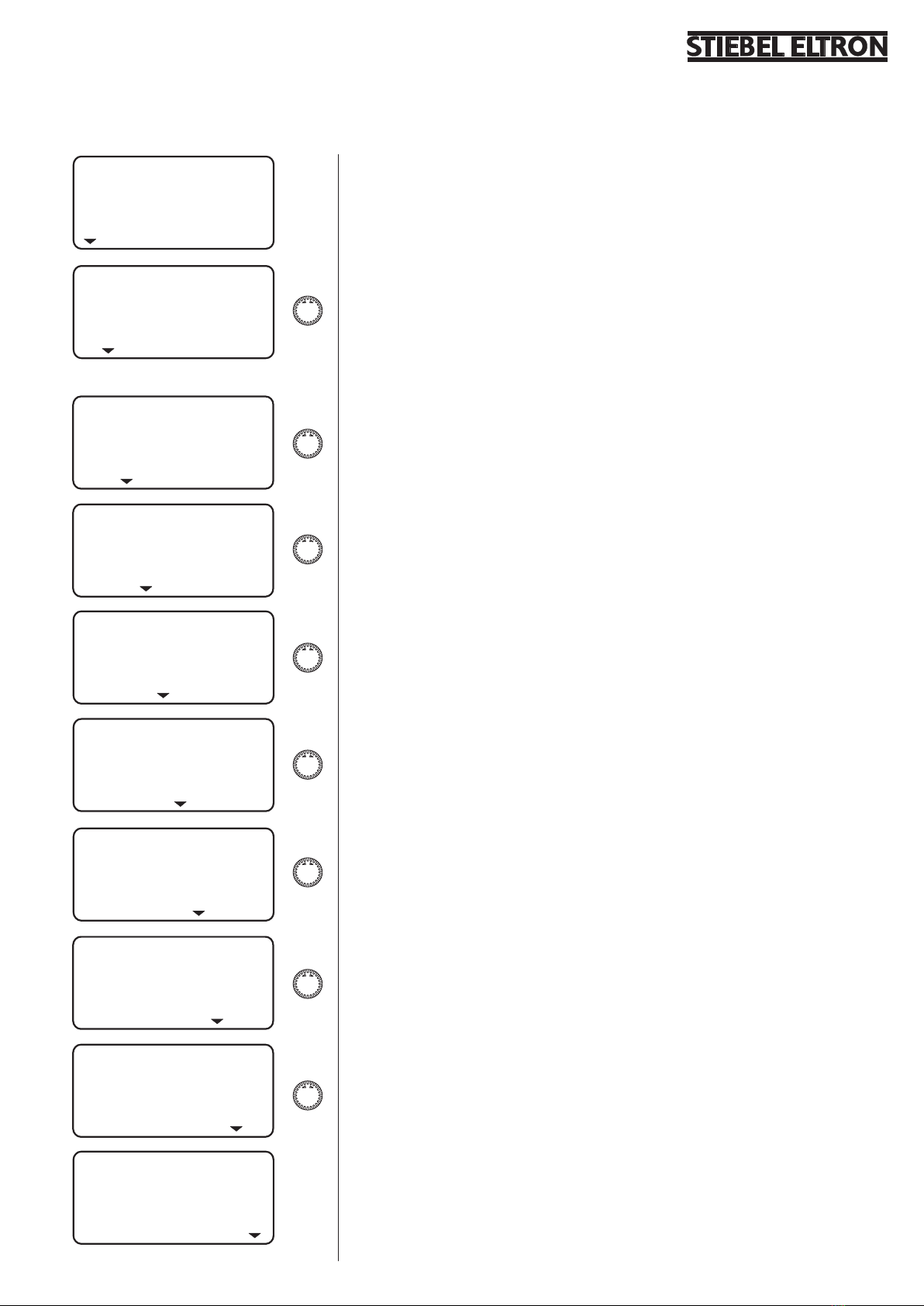
Vital facts in brief
Adjustments
All adjustments follow the same pattern:
Opening the control flap toggles the man-
ager into programming mode. An indica-
tor symbol is shown at the bottom of
the display at system parameter ROOM
TEMP 1.
Turning the rotary selector allows you
to move the indicator to the system pa-
rameter you want to change.
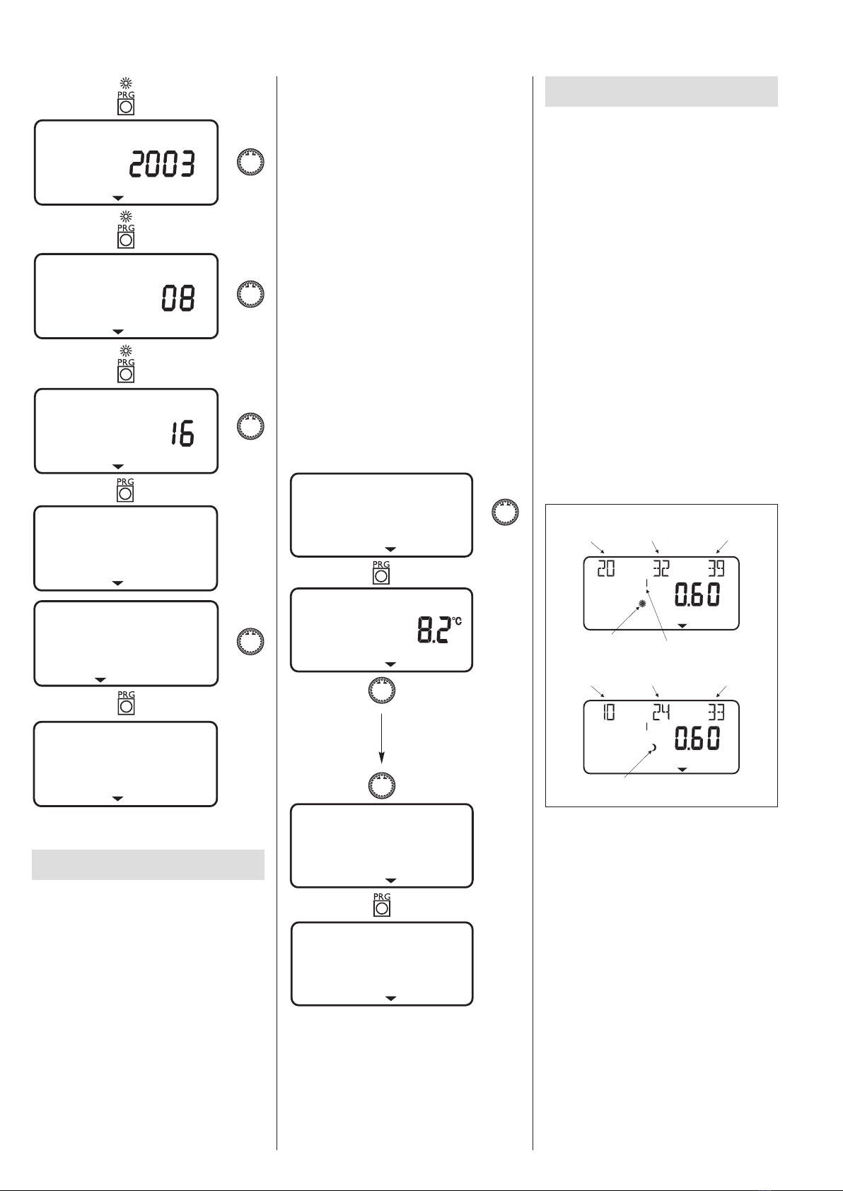
Press to change the system parameter.
Whenever the red indicator above illu-
minates, you can modify the current value
by turning the rotary selector . Press
again; the illuminator then goes out and
the new set value has been saved. You can
modify further values for this menu item
by pressing , if the red indicator has not
been extinguished above .
The programming step can only be ter-
minated when the red indicator has gone
out.
Terminating the programming process
You can terminate the programming proc-
ess after entering and saving the require
menu point changes by closing the control
flap. However, if you want to make further
changes, turn the rotary selector until
the display shows BACK, then press
This will return you to the previous level.
Closing the control flap with illuminated in-
dicator above returns the manager into
its original position. The modified value will
not have been saved.
During commissioning, a system
check will be implemented, e.g. all
sensors that are currently connected, are
displayed upon request. Sensors not con-
nected before the system went 'live' are
not registered by the manager and are
therefore not displayed. The indicator sym-
bol skips the system parameter.
Example: The system parameters DHW
TEMP and DHW PROG will be skipped if,
during commissioning, the DHW cylinder sen-
sor was not connected. Values for these pa-
rameters can therefore not be programmed.
1.7 What to do if . . . ?
. . . there is no hot water or the heating sys-
tem stays cold:
Check the fuse/circuit breaker in your fuse
box. If it has blown/tripped, replace/reset the
fuse/MCB. Notify your local contractor if the
fuse/MCB blows/trips again.
Notify your local contractor in case
of all other faults.
Control level 2 (control flap open)
This enables system parameters, such as room
temperature, DHW temperature, heating pro-
grams, etc. to be adjusted (see section 1.8.2).
Control level 3 (for contractors only)
This level is protected by a code and should
only be used by contractors. At this level, heat
pump and system-specific details are deter-
mined (see section 2.10).