STIEBEL ELTRON SP cool User manual

INSTALLATION
INSTALLATIE
INSTALLAZIONE
Splitter für Heizkreisventile |Splitter for heating circuit valves | Distributeur pour
vanne de circuit de chauffage| Splitter voor verwarmingscircuitventielen | Split per
valvole del ciclo
» SP cool

12 | SP cool www.stiebel-eltron.com
CONTENTS | INSTALLATION
General information
INSTALLATION
1. General information ��������������������������������������� 12
1.1 Safety instructions���������������������������������������������� 12
1.2 Other symbols in this documentation ���������������������� 12
1.3 Units of measurement ����������������������������������������� 13
2. Safety�������������������������������������������������������� 13
2.1 Intended use����������������������������������������������������� 13
2.2 General safety instructions ����������������������������������� 13
2.3 Instructions, standards and regulations ������������������� 13
2.4 CE designation �������������������������������������������������� 13
3. Troubleshooting �������������������������������������������� 13
4. Appliance description ������������������������������������� 13
5. Preparations������������������������������������������������ 13
5.1 Installation site�������������������������������������������������� 13
6. Installation�������������������������������������������������� 13
7. Specification ������������������������������������������������ 14
7.1 Connection diagrams ������������������������������������������ 14
7.2 Wiring diagrams ������������������������������������������������ 16
7.3 Data table �������������������������������������������������������� 18
GUARANTEE
ENVIRONMENT AND RECYCLING
INSTALLATION
1. General information
The chapter "Installation" is intended for qualified contractors.
Note
Read these instructions carefully before using the appli-
ance and retain them for future reference.
Pass on the instructions to a new user if required.
1.1 Safety instructions
1.1.1 Structure of safety instructions
!
KEYWORD Type of risk
Here, possible consequences are listed that may result
from failure to observe the safety instructions.
Steps to prevent the risk are listed.
1.1.2 Symbols, type of risk
Symbol Type of risk
Injury
Electrocution
1.1.3 Keywords
KEYWORD Meaning
DANGER Failure to observe this information will result in serious
injury or death.
WARNING Failure to observe this information may result in serious
injury or death.
CAUTION Failure to observe this information may result in non-seri-
ous or minor injury.
1.2 Other symbols in this documentation
Note
General information is identified by the symbol shown
on the left.
Read these texts carefully.
Symbol Meaning
Material losses
(appliance damage, consequential losses and environmen-
tal pollution)
Appliance disposal
This symbol indicates that you have to do something. The ac-
tion you need to take is described step by step.
!
!

www.stiebel-eltron.com SP cool | 13
ENGLISH
INSTALLATION
Safety
1.3 Units of measurement
Note
All measurements are given in mm unless stated oth-
erwise.
2. Safety
2.1 Intended use
This device is designed to connect room temperature controllers
and their associated electro-thermal actuators.
Only a qualified contractor should carry out installation, commis-
sioning, maintenance and repair of the appliance.
This appliance is intended for domestic use. The appliance can also
be used in a non-domestic environment, e.g. in a small business,
as long as it is used in the same way.
Any other use beyond that described shall be deemed inappropri-
ate. Observation of these instructions and of instructions for any
accessories used is also part of the correct use of this appliance.
2.2 General safety instructions
We guarantee trouble-free function and operational reliability only
if original accessories and spare parts intended for the appliance
are used.
2.3 Instructions, standards and regulations
Note
Observe all applicable national and regional regulations
and instructions.
2.4 CE designation
The CE designation shows that the appliance meets all essential
requirements according to the:
- Electromagnetic Compatibility Directive (Council Directive
89/336/EEC)
- Low Voltage Directive (Council Directive 73/23/EEC)
- DIN EN 60730 Part 1: Automatic electrical controls for domes-
tic and similar use
The rating plate is located on the inside of the device cover.
3. Troubleshooting
If you cannot remedy the fault, notify your qualified contractor.
To facilitate and speed up your request, provide the number from
the type plate (000000-0000-000000).
4. Appliance description
This device is wired into the control panel and is intended for
wiring up room temperature controllers and electro-thermal ac-
tuators.
This device is suitable for underfloor heating and cooling systems
(summer/winter mode).
Rooms can only be cooled if the heat pump manager is in summer
mode.
In the rooms to be cooled, the actuator-operated valves of the
heating circuits open.
Up to 6 electro-thermal 230V heating circuit valves can be con-
nected to the device. If you use several splitters, the Cooling signal
from the heat pump manager will be looped through.
The appliance is fully wired, for immediate connection to a 230 V
socket. The indicator on the front of the device illuminates when
mains voltage is present.
5. Preparations
5.1 Installation site
!
Material losses
Operate this device exclusively in dry enclosed spaces
with conventional ambient conditions.
Mount the device in the electrical or heating circuit
distributor.
6. Installation
WARNING Electrocution
Always isolate the device from the power supply
before installation and maintenance.
The device is for mounting on a top-hat rail, in the electrical or
heating circuit distributor for example. It can be installed in any
position.
Isolate the appliance from the power supply.
Connect the temperature controller and the actuators to the
terminals.
Connect the device to the power supply.
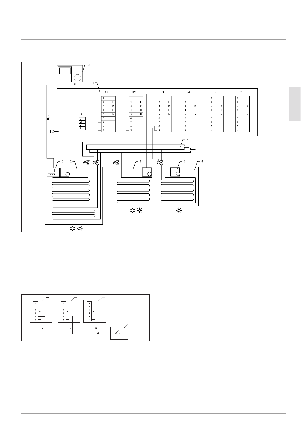
6.1.1 Connecting the temperature controllers and actuators
Connect the room temperature controller and the actuators
for Room1 to terminalR1.
Connect the room temperature controllers and the actuators
for Rooms2-6 following the same pattern.
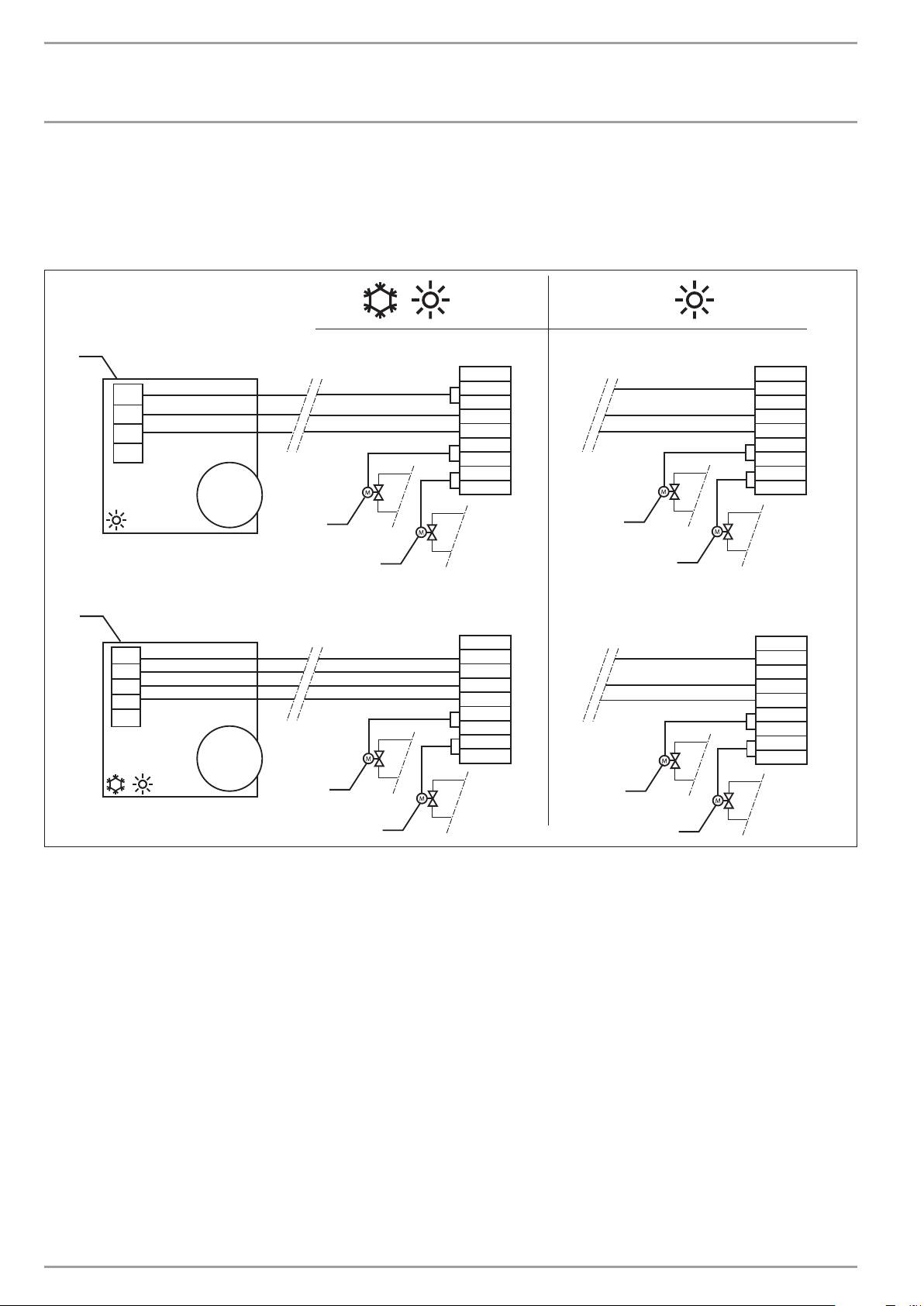
The wiring may vary subject to the type of room temperature
controller (see chapter "Specification/Connection diagrams").
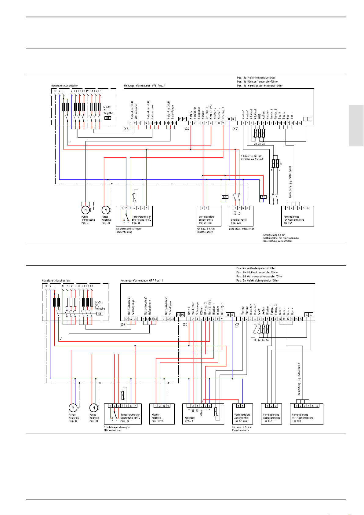
Changeover between heating/cooling
Connect the Cooling output of the heat pump manager to terminal
X1/e.
For wiring diagrams for heat pumps WPLcool, WPF, WPW and
WPCcool, see chapter "Specification/ Wiring diagrams".

14 | SP cool www.stiebel-eltron.com
INSTALLATION
Specication
7. Specification
7.1 Connection diagrams
Wiring of room temperature controllers
R1
L
L
N
N
N
N
1
2
3
4
5
6
7
8
9
L
N
1
2
3
3
3
3
H
H
K
H
K
R1
1
2
3
4
5
6
7
8
9
L
N
H
K
R1
1
2
3
4
5
6
7
8
9
L
N
H
K
R1
1
2
3
4
5
6
7
8
9
L
N
H
K
3
3
3
3
26�03�01�0736
1 Room thermostat, heating only
2 Room thermostat, heating and cooling
3 Actuating valves, room 1
K Cooling
H Heating
L Phase
N Neutral conductor

www.stiebel-eltron.com SP cool | 15
ENGLISH
INSTALLATION
Specication
Splitter wiring
26�03�01�0735
1 SP cool distributor strip
2 Room 1, heating and cooling
3 Room 2, heating and cooling
4 Room 3, heating only
5 Single room thermostat (on site)
6 FEK digital remote control
7 Heating circuit distributor
8 Heat pump manager WPMi
Wiring several splitters
123
4
cool
26�03�01�0741
1 Distributor strip 1
2 Distributor strip 2
3 Distributor strip n
4 Coolingsignal from the heat pump manager
Table of contents
Popular Media Converter manuals by other brands

H&B
H&B TX-100 Installation and instruction manual

Bolin Technology
Bolin Technology D Series user manual

IFM Electronic
IFM Electronic Efector 400 RN30 Series Device manual

GRASS VALLEY
GRASS VALLEY KUDOSPRO ULC2000 user manual

Linear Technology
Linear Technology DC1523A Demo Manual

Lika
Lika ROTAPULS I28 Series quick start guide

Weidmuller
Weidmuller IE-MC-VL Series Hardware installation guide

Optical Systems Design
Optical Systems Design OSD2139 Series Operator's manual

Tema Telecomunicazioni
Tema Telecomunicazioni AD615/S product manual

KTI Networks
KTI Networks KGC-352 Series installation guide

Gira
Gira 0588 Series operating instructions

Lika
Lika SFA-5000-FD user guide