STIF VIGIBELT TOUCH ATEX (II 2 D) User manual
INSTRUCTION MANUAL VIGIBELT®TOUCH ATEX (II 2 D) GB –1/4
www.stifnet.com - VER. 01/16 - N° DOC BE0455041
FUNCTION
- The VIGIBELT®TOUCH is a lateral movement sensor that detects run-out of elevator belts or conveyor belts, and
at the same time the run-out of the lift pulley. It reacts to the pressure of the belt coming into contact with the front
face of the sensor. Baffle plates are usually fitted opposite each other, preferably on the upward leg close to the
pulleys for elevators, and on the load bearing side close to the drums for conveyors.
The sensors can be connected directly to a PLC, or for absolutely safety, to an independent "monitoring M-JET”
central unit. The electrical circuit can control an alarm or a machine shut down.
- For elevators more than 20 meters long, we recommend fitting the head with a second VIGIBELT®TOUCH kit, still
on the upward leg.
- The sensors trigger when the belt applies a force of approximately 5 daN.
DESCRIPTION
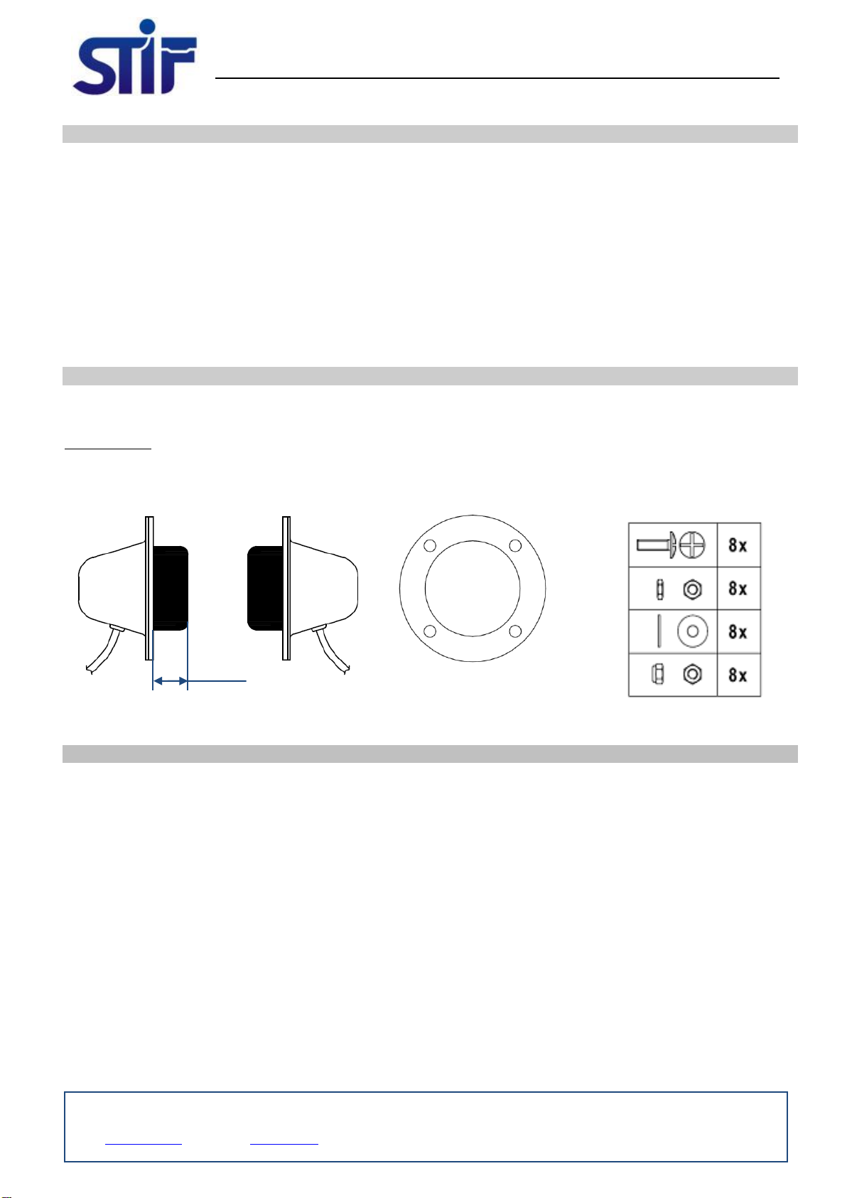
- The VIGIBELT®TOUCH kit comprises two sensors, four elastomer spacers (3mm NBR) and the fastenings (M6).
Composition :
PRECAUTIONS
The VIGIBELT®TOUCH must be installed, connected and put into service by competent personnel. The personnel
should be qualified electricians and know the regulations and requirements concerning the installation of these
appliances, especially when installed in ATEX areas.
- Carry out a study prior to the electrical connection of the VIGIBELT®TOUCH sensors (standardised electrical
diagram, PLC control, electricity supply and protection).
- Define the sensing distance between the belt and the elevator shaft (confirmation of the triggering distance by the
person in charge of the site).
- Before any installation or intervention on the VIGIBELT®TOUCH, it is essential to make sure that the bucket
elevator is shut down (intervention warning to be posted on the machine).
- When the VIGIBELT®TOUCH is dismantled, the user should ensure that the appliance is scrapped properly and
that the components are passed to the appropriate specialist collection centres according to their nature (stainless
steel, electrical equipment, seals, etc.).
Z.A. de la lande - 49170 Saint-Georges-sur-Loire - France
Siège social, achats et usine : tél.: +33 2 41 72 16 80 - Fax +33 2 41 72 16 85
Service commercial France Export : tél.: +33 2 41 72 16 82 - Fax +33 2 41 39 32 12
Email : sales@stifnet.com - Site internet : www.stifnet.com
SAS au capital de 800 000 € - R.C.S. Angers B 328 876 503 - 84B12 APE 2511Z - N° TVA FR 35 328 876 503
2x VIGIBELT®TOUCH
4x elastomer spacers (th.3mm)
8x mounting bolts (M6)
23mm

INSTRUCTION MANUAL VIGIBELT®TOUCH ATEX (II 2 D) GB –2/4
www.stifnet.com - VER. 01/16 - N° DOC BE0455041
INSTALLATION
1) Make two symmetrical round openings on each side of the up shaft of an elevator (56mm dia. + 4 7mm dia. holes
on a PCD of 72mm): DIagram-A
Diagram A
On a conveyor belt position the VIGIBELT®
TOUCH sensors on the load carrying side close to
the axis of the drum and the belt.
On a bucket elevator position the VIGIBELT® TOUCH
sensors on the upward leg close to the axis of the
pulleys and the belt.
Make the 56mm opening
on the belt axis
sangle
Belt
INSTRUCTION MANUAL VIGIBELT®TOUCH ATEX (II 2 D) GB –3/4
www.stifnet.com - VER. 01/16 - N° DOC BE0455041
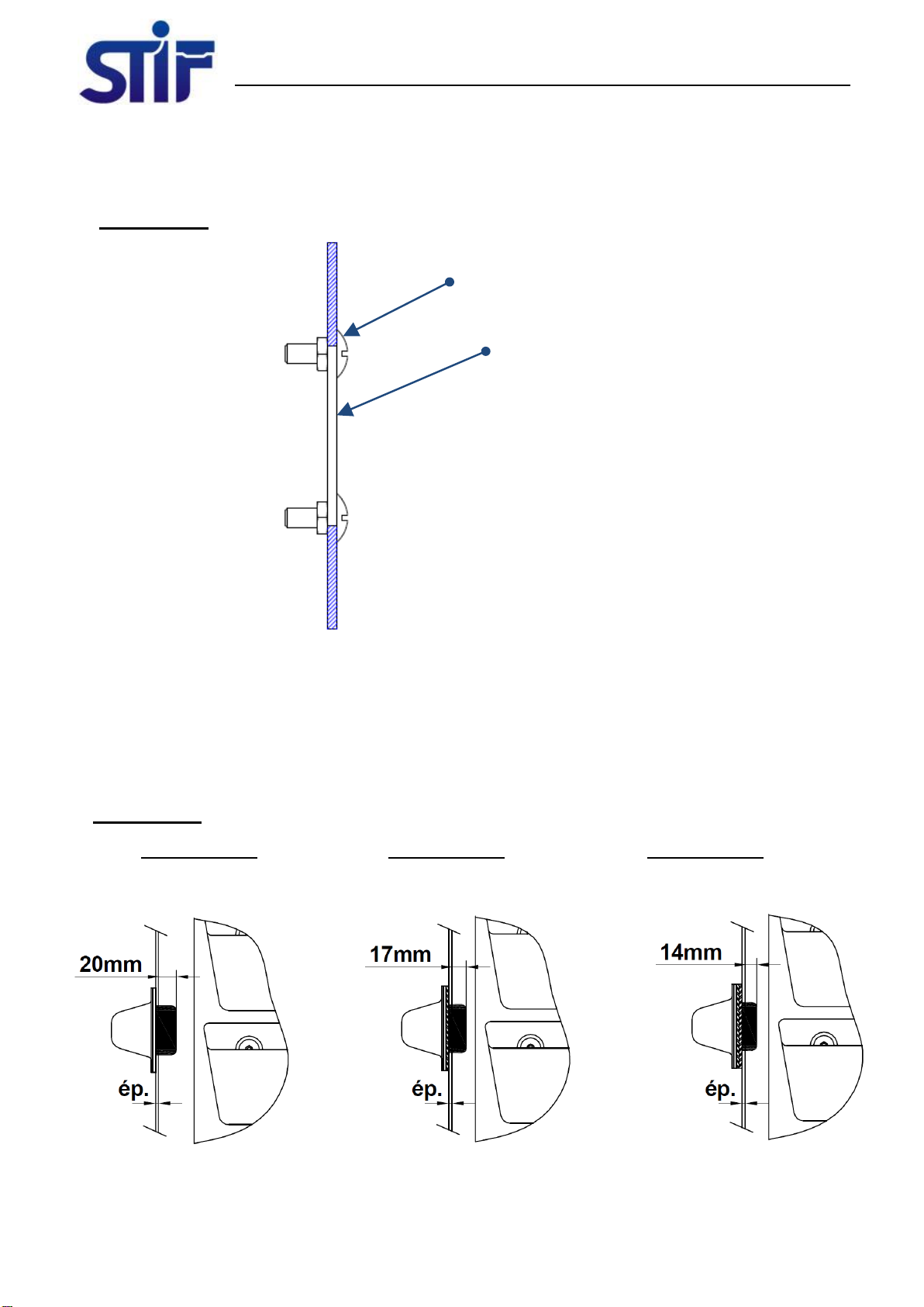
2) Fit the M6 pan head screws with the low nuts on the shaft (torque 6 N.m): Biagram-B.
3) Adjust the triggering distance of the VIGIBELT®TOUCH sensors. This distance is the dimension between the
inside face of the elevator and the contact face of the sensor.
To achieve this, three detection adjustments are possible, diagram-C:
No 1 - Sensor with no additional spacer, elevator thickness (e.g.: 3mm), i.e. a distance of 20mm
No 2 - Sensor with one additional spacer, elevator thickness (e.g.: 3mm), i.e. a distance of 17mm
No 3 - Sensor with two additional spacers, elevator thickness (e.g.: 3mm), i.e. a distance of 14mm
Diagram B
On the inside face of the shaft
Fit pan head screws + low nuts
Diagram C
Adjustment no 1
Distance of 20mm,
With no additional spacer
Adjustment no 2
Distance of 17mm,
with one additional spacer
Adjustment no 3
Distance of 14mm,
with two additional spacers
INSTRUCTION MANUAL VIGIBELT®TOUCH ATEX (II 2 D) GB –4/4
www.stifnet.com - VER. 01/16 - N° DOC BE0455041
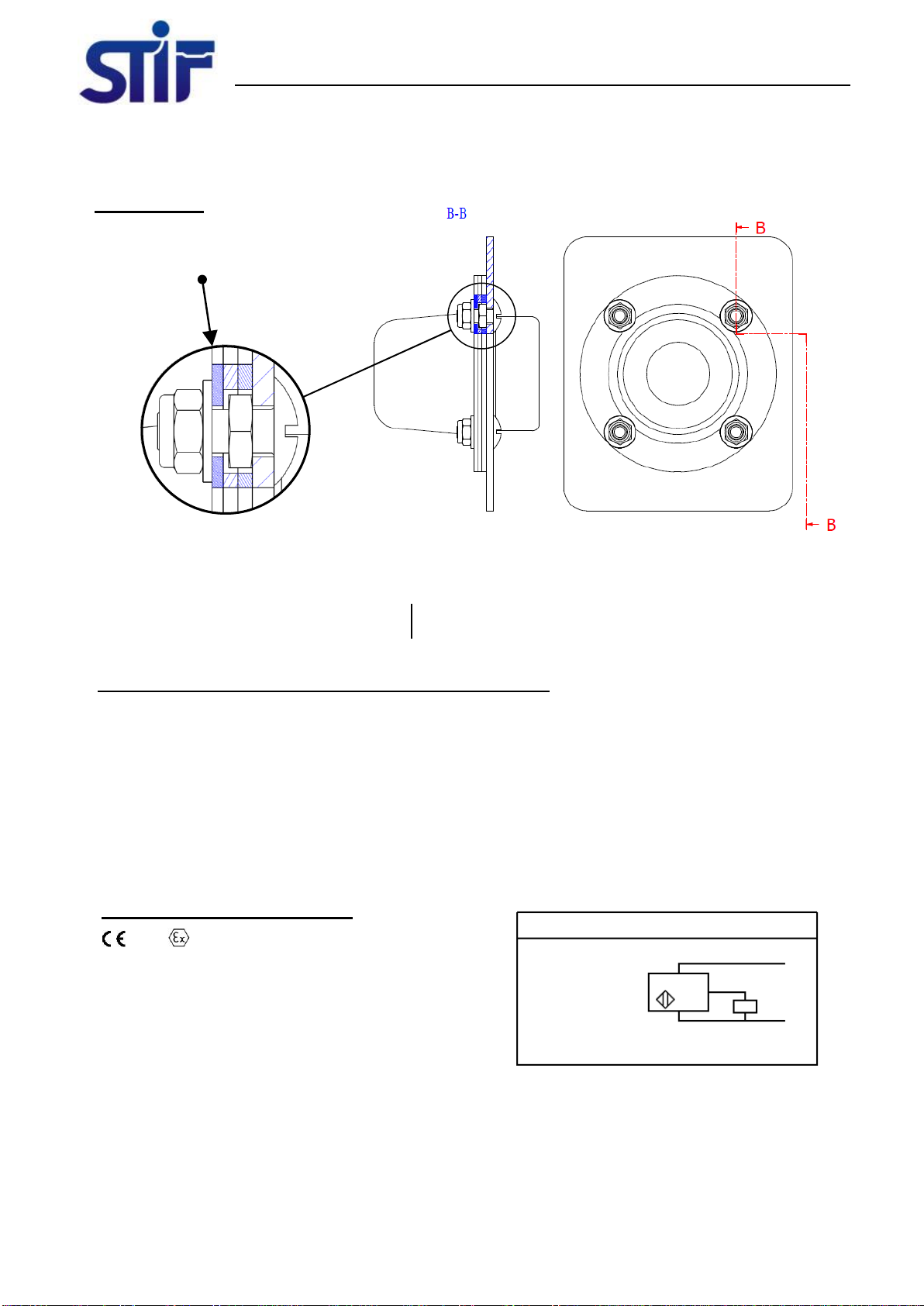
4) Position the VIGIBELT®TOUCH sensors on the openings and tighten the M6 locknuts (torque 4 N.m) according
to Diagram-D.
5) Connect the VIGIBELT®TOUCH sensors according to the electrical diagrams:
NC sensor = positive safety, continuous sensor function monitoring
Loss of the signal indicates a problem of Belt run-out
Wiring open circuit
6) After completing the mechanical and electrical installation of the VIGIBELT®TOUCH sensors, you should check
each sensor to make sure that they are all working. To do this, trigger each sensor by pressing its contact face.
This simulation serves to confirm that the fault information is transmitted to the monitoring system (monitoring M-
JET, supervisor PLC).
VIGIBELT®TOUCH for area ATEX 21 (II 2 D) - 55KVT72616TE
- Connection by cable: 10 m (3 wires)
- Rated supply voltage: 12 to 24V DC
- Voltage limits (incl.wave): 10 to 36V DC
- Switching capacity in mA: <= 100 mA
with protection against overloads and short-circuits
- Protection - IP67 according to IEC 60529
- Temp: -20° C < Ta < 60° C
Connection diagram - 3 wires
Wire colours
BN = Brown
BU = Blue
BK = Black
PVC cable - 10m; 3x0.34mm²
BN
BK
BU
+
-
NC/PNP
Diagram D
Fix the VIGIBELT®TOUCH sensor
with the washers and locknuts
Inside sensor - XS7E1A1PBL10EX
0080 II 2 D –Ex tb IIIC T90° C Db IP67
INERIS 06ATEX0065X
- Do not disconnect when energized
- Prevent from dust deposits
- EU Declaration of Conformity Nr/S1A42203_03
- Technical document Nr/S1A41508_00
Table of contents
Popular Accessories manuals by other brands

Lightolier
Lightolier D14 specification

Craftsman
Craftsman 509344 owner's manual

Samsung
Samsung SIP-1201DD user manual

Byron
Byron B002E quick start guide

PCB Piezotronics
PCB Piezotronics 106M131 Installation and operating manual

Motorisation+
Motorisation+ SAFEDUO Instructions and warnings for installation and use


