manuals.online logo
Brands
  1. Home
  2. •
  3. Brands
  4. •
  5. YOKOGAWA
  6. •
  7. Accessories
  8. •
  9. YOKOGAWA PBDH0150 User manual

YOKOGAWA PBDH0150 User manual

IM 701927-01EN 1/2
Use
r’s
Manual
Notes
• The contents of this manual are subject to change without prior notice as a result of continuing
improvements to the product’s performance and functionality. The figures given in this manual may
differ from those that actually appear on your product.
• Every effort has been made in the preparation of this manual to ensure the accuracy of its
contents. However, should you have any questions or find any errors, please contact your nearest
YOKOGAWA dealer.
• Copying or reproducing all or any part of the contents of this manual without the permission of
YOKOGAWA is strictly prohibited.
Conventions Used in This Manual
Improper handling or use can lead to injury to the user or damage to the instrument.
This symbol appears on the instrument to indicate that the user must refer to the
user’s manual for special instructions. The same symbol appears in the corresponding
place in the user’s manual to identify those instructions. In the manual, the symbol is
used in conjunction with the word “WARNING” or “CAUTION.”
WARNING Calls attention to actions or conditions that could cause serious or fatal injury to the
user, and precautions that can be taken to prevent such occurrences.
CAUTION Calls attention to actions or conditions that could cause light injury to the user or
cause damage to the instrument or user’s data, and precautions that can be taken to
prevent such occurrences.
Note Calls attention to information that is important for the proper operation of the
instrument.
Safety Precautions
This instrument is designed to be used by a person with specialized knowledge.
The general safety precautions described herein must be observed during all phases of operation.
YOKOGAWA assumes no liability for the customer’s failure to comply with these requirements.
In addition, before using the probe, read the manuals of the measuring instrument to thoroughly
familiarize yourself with its specifications and operation.
This manual is part of the product and contains important information. Store this manual in a safe place
close to the instrument so that you can refer to it immediately. Keep this manual until you dispose of
the instrument.
The following symbols are used on this instrument.
Handle with care. Refer to the user’s manual or service manual. This symbol appears on
dangerous locations on the instrument which require special instructions for proper handling
or use. The same symbol appears in the corresponding place in the manual to identify those
instructions.
Risk of electric shock
Notes about Usage
WARNING
Ground the oscilloscope
Make sure to connect the protective grounding terminal of the oscilloscope to ground.
Check grounding
Before connecting the probe input terminal to the circuit under measurement, ensure that the
measuring instrument is grounded properly and that the probe’s BNC connector is connected
the oscilloscope input.
Be careful of electric shock
Never use the probe with wet hands or when the probe itself is wet. Doing so may cause
electric shock. Be careful of electric shock when you connect the probe to the circuit under
measurement.
Observe the maximum input voltage
Do not apply voltage exceeding 1400 V (DC + ACpeak) between an input lead and ground or
between two input leads. The maximum input voltage is 1400 V (DC + ACpeak) regardless
of whether 50:1 or 500:1 attenuation is used.
Do not touch exposed circuitry
To prevent injury, do not touch exposed live connections or components.
Connect and disconnect the probe properly
Do not disconnect the probe from the oscilloscope while the probe is connected to the circuit
under measurement. Doing so may cause electric shock.
Do not use in damp places
To prevent electric shock, do not use the probe in damp places.
Do not use in an explosive atmosphere
To prevent fire and injury, do not use the probe in a flammable or explosive atmosphere or
near steam.
Do not disassemble or modify
Do not disassemble or modify the product. YOKOGAWA assumes no liability if you
disassemble or modify the product.
Damaged Signal Cable
If the signal cable is torn and the inner metal is exposed or if a color different from the outer
sheath appears, stop using the cable immediately.
Stop use if you suspect damage
If you suspect that the probe is broken, consult your nearest YOKOGAWA dealer.
Thank you for purchasing the PBDH0150 Differential Probe (Model 701927). This user’s manual
explains the usage, specifications, and handling precautions. To ensure correct use, please read this
manual thoroughly before beginning operation. After reading this manual, keep it in a safe place.
IM 701927-01EN
8th Edition
CAUTION
• This product has not been designed or manufactured for applications in which high
reliability is required over a long period of time. This probe is not water or dust resistant.
Do not use the probe in areas with a lot of dust or where water may be spilled.
• Avoid storing or using the probe in direct sunlight or in areas with high temperature,
humidity, or condensation. Deformation and insulation deterioration can occur causing
the probe to no longer meet the specifications.
• Avoid vibration, shock, and static electricity during shipping and handling. Take extra care
not to drop the probe.
Operating Environment Limitations
See below for operating environment limitations.
CAUTION
This product is a Class A (for industrial environments) product. Operation of this product in
a residential area may cause radio interference in which case the user will be required to
correct the interference.
1. Overview
The PBDH0150 Differential Probe (Model 701927) is a 150 MHz bandwidth, high-voltage,
differential input probe that is used in combination with DLM series or other digital oscilloscopes that
have the YOKOGAWA probe interface (hereafter referred as oscilloscope with the probe IF).*
To use the probe, simply connect it to a BNC input terminal on an oscilloscope with the probe IF.
Touch the device under measurement with the probe tip to observe the voltage waveform.
2. Configuration and Part Names
Cable
2
1
Input leads
5
Overload indicator
Attenuation
switch
3 4
Probe interface
Probe head
O-rings
(8 colors)
To oscilloscope
input
Latch release lever BNC connector
Interface spring pin
Probe interface
Variable resistor for
adjusting offset voltage
Standard Parts Part No. Accessories Sold separately Part No.
1. Pincher tips (Black) B9852MM Long test clip 701906
(Red) B9852MN Alligator clip (dolphin type) 701954
2. Extension leads (1 m) (Black) B8099LF Fork terminal adapter 758921
(Red) B8099LG Alligator clip adapter (rated 300 V) 758922
3. 100 Ω resistance adapters x 2 (yellow) B8099LJ Alligator clip adapter (rated 1000 V) 758929
4. 150 Ω resistance adapters x 2 (green) B8099LK Safety terminal adapter 758931
5. Manuals (see below)
Manual Title Manual No. Description
Model 701927
PBDH0150 Differential Probe
User’s Manual
IM 701927-01EN This manual
Model 701927
PBDH0150 Differential Probe
Safety Instructions
IM 701927-02FR The warnings and cautions in French to
supplement the IM 701927-01EN
Safety Instruction Manual IM 00C01C01-01Z1 Safety manual (European languages)
Inquiries PIM 113-01Z2 List of worldwide contacts
The “EN”, “FR”, “Z1” and “Z2” in the manual numbers are the language codes.
Attenuation Switch
Switches between 50:1 and 500:1 attenuation.
Overload Indicator
When the differential input voltage exceeds the following value, the indicator lights.
±140 V (DC + ACpeak) at 50:1 attenuation
±1400 V (DC + ACpeak) at 500:1 attenuation
Probe Interface
The section of the probe that connects to the digital oscilloscope input.
Interface Spring Pins
When the probe interface is connected, these pins touch the pad on the oscilloscope interface
board. The probe’s power is supplied through these interface pins. These interface pins are also
used by the oscilloscope to automatically detect the probe attenuation setting.
Latch Release Lever
Releases the lock connecting the probe interface to the oscilloscope input.
Variable Resistor for Adjusting Offset Voltage
You can adjust the offset voltage using an appropriate screwdriver as described below.
L
W
Adjustment Screwdriver
Use an adjustment screwdriver that matches the adjustment groove. Using a
screwdriver with a large grip or a screwdriver with a small head can damage
the adjustment turn stop or groove.
Recommended adjustment driver bit dimensions
Head thickness (W): 0.2 to 0.35 mm; head width (L): 1.3 to 1.5 mm;
head shape: flat or Philips
Model 701927
PBDH0150 Differential Probe
8th Edition: December 2021 (YMI)
All Rights Reserved, Copyright © 2012, Yokogawa Test & Measurement Corporation
Printed in Japan
IM 701926-01EN 2/2
General Specifications
Item Specifications
Operating environment Probe (excluding the pincher tip)
5°C to 40°C, 25% to 85% RH (no condensation)
Pincher tip
–40°C to 85°C, 25% to 85% RH (no condensation)
Extension lead
–40°C to 85°C, 25% to 85% RH (no condensation)
Storage environment –30°C to 60°C, 25% to 85% RH (no condensation)
(probe, excluding the pincher tip)
Operating altitude 2000 m or less
Storage altitude 3000m or less
Recommended calibration
period
1 year
Warm-up time At least 30 minutes
External dimensions 174 mm × 58 mm × 27 mm (excluding the connector and cable)
Total length 2420 mm ± 30 mm
Weight Approx. 300 g (probe, excluding the pincher tip)
Compliant
standards
Safety
standards8, 9
Probe (excluding the pincher tip)
EN 61010-031
Measurement category II 1000 Vrms
Pollution degree 2
Pincher tip
EN 61010-031
Measurement category III 1000 Vrms
Pollution degree 2
Extension lead
EN 61010-031
Measurement category III 1000 Vrms
Pollution degree 2
Probe and accessories
EN 61010-031
Measurement category II 1000 Vrms
Pollution degree 2
EMC standards Emission10 EN 61326-1 Class A
EN 55011 Class A, Group 1
EMC regulations in Australia and New Zealand
EN 55011 Class A, Group 1
Immunity EN 61326-1 Table 2
Environmental
standards11
EU RoHS Directive compliant
8 This product is for measurement category II (CAT II). Do not use it for measurement category III
(CAT III) or IV (CAT IV). When using devices with different measurement categories, the lower
measurement category applies. Because the measurement category of the probe is lower than
its accessories, when the probe and its accessories are used together, measurement category II
(CAT II) applies.
Measurement Category Definition
Measurement category “O” (Other) Measurement category O (Other) applies to
measurement of a circuit that is not connected directly
to the main power source.
Measurement category II (CAT II) CAT II applies to measurement of electrical equipment
that is powered through a fixed installation such
as a wall outlet wired to a distribution board and
measurement on such wiring.
Measurement category III (CAT III) CAT III applies to measurement at the distribution level,
that is, building wiring, fixed installations.
Measurement category IV (CAT IV) CAT IV applies to measurement at the primary supply
level, that is, overhead lines, cable systems.
9 Pollution degree refers to the degree of adhesion of a solid, liquid, or gas which deteriorates
withstand voltage or surface resistivity. Pollution Degree 2 applies to normal indoor atmospheres
(with only non-conductive pollution).
10 This product is a Class A (for industrial environments) product. Operation of this product in a
residential area may cause radio interference in which case the user will be required to correct
the interference.
11 For conformity to environmental regulations and/or standards other than EU, contact your local
Yokogawa office.
Waste Electrical and Electronic Equipment (WEEE)
(EU WEEE Directive valid only in the EEA* and UK WEEE Regulation in the UK)
This product complies with the WEEE marking requirement. This marking indicates
that you must not discard this electrical/electronic product in domestic household
waste. When disposing of products in the EEA or UK, contact your local Yokogawa
office in the EEA or UK respectively.
* EEA: European Economic Area
Authorized Representative in the EEA (AR)
Yokogawa Europe B.V. is the authorized representative of Yokogawa Test & Measurement Corporation
for this product in the EEA. To contact Yokogawa Europe B.V., see the separate list of worldwide
contacts, PIM 113-01Z2.
Disposal
When disposing of YOKOGAWA products, follow the laws and ordinances of the country or region
where the product will be disposed of.
Compliance with the Radio Waves Act (Republic of Korea)
This product complies with the Radio Waves Act (Republic of Korea). Note the following when using
the product in Republic of Korea.
 이 기기는 업무용(A 급 ) 전자파적합기기로서 판 매자 또는 사용자는 이 점을 주의하시기
바라며 , 가정외의지역에서사용하는것을목적으로합니다 .
(The product is for business use (Class A) and meets the electromagnetic compatibility
requirements. The seller and the user must note the above point and use the product in a place
except for home.)
Registration No: KCC-REM-IMY-EEN335
Equipment Name: Differential Probe
Trade Name: Yokogawa Test & Measurement Corporation
Manufacturer: Yokogawa Test & Measurement Corporation
Country of Origin: Japan
产品中有害物质的名称及含量
This section is valid only in China.
部件名称 有害物质
铅 (Pb)汞 (Hg)镉 (Cd)六价铬 (Cr(VI)) 多溴联苯 (PBB) 多溴二苯醚 (PBDE)
框架 ( 塑料) ×○ ○ ○ ○ ○
线路板 ASSY ×○ ○ ○ ○ ○
○ : 表示该有害物质在该部件所有均质材料中的含量均在 GB/T 26572 规定的限量要求以下。
× : 表示该有害物质至少在该部件的某一均质材料中的含量超出 GB/T 26572 规定的限量要求。
环保使用期限 :
该标识适用于 SJ/T 11364 中所述,在中华人民共和国销售的电子电气产品的
环保使用期限。
只要您遵守该产品相关的安全及使用注意事项,在自制造日起算的年限内,则
不会因产品中有害物质泄漏或突发变异,而造成对环境的污染或对人体及财产
产生恶劣影响。
注)该年数为“环保使用期限”, 并非产品的质量保证期。零件更换的推荐周期,
请参照使用说明书。
3. How to Use
WARNING
• Turn off the power to the circuit under measurement when you connect or disconnect
the probe from the circuit. Connecting or removing the probe while the power is on
is dangerous. Do not touch the probe after turning on the power to the circuit under
measurement.
• Do not disconnect the probe’s BNC connector from the oscilloscope while the probe is
connected to the circuit under measurement. Before disconnecting the BNC connector,
turn off the power to the circuit under measurement, and disconnect the probe from the
high voltage parts of the circuit.
CAUTION
• This probe is designed to measure the voltage difference between two points on the
circuit under measurement. It does not electrically isolate the circuit under measurement
from the measuring instrument.
• Use a soft cloth to clean the probe. Be careful not to break the probe.
Do not immerse the probe in liquid or use abrasive cleaners on the probe. Do not use
benzene or other solvents on the probe.
Preparation
1.
Have the probe and an oscilloscope with the probe IF ready.
2.
Insert the probe interface completely into the oscilloscope input, and confirm that the BNC
connector and interface pin are securely fastened. You will hear the latch click when the
connectors lock into place.
3.
When you connect the probe to an oscilloscope with the probe IF, the attenuation ratio and
input coupling on the oscilloscope are set automatically. If you change the attenuation ratio
of the probe using the attenuation switch, the attenuation ratio on the oscilloscope changes
automatically.
4.
If necessary, attach the provided extension leads, pincher tips, and resistance adapters to the
input leads.
Connecting Accessories
If you are using input leads and pincher tips, use the 100 Ω resistance adapters.
Input leads
Pincher tips
100 Ω resistance adapters (yellow)
If you are connecting extension leads (1 m) to input leads, use the 150 Ω resistance adapters.
Input leads
Pincher tips
150 Ω resistance adapters (green)
Extension leads (1m)
Note
• Accurate measurements may not be possible near objects with strong electromagnetic fields
such as transformers, large current circuits, and wireless equipment.
• Before use, flip the attenuation switch back and forth several times. The switch’s electrical
contacts can weaken if not used for long periods of time.
• To take accurate measurements, we recommend that you calibrate the probe once a year.
4. Specifications
Electrical Specifications
Item Specifications
Frequency bandwidth1, 2 DC to 150 MHz (–3 dB)6
Using the extension leads (typical)3: DC to 100 MHz (−3 dB)7
Input type Balanced differential input
Attenuation 50:1 or 500:1, switchable
Input resistance and
capacitance (typical)3
4 MΩ + 5 pF (to ground)
Allowable differential voltage
(between + and – terminals)
±140 V (DC + ACpeak) at 50:1 attenuation
±1400 V (DC + ACpeak) at 500:1 attenuation
Allowable common mode
voltage
±1400 V (DC + ACpeak) or 1000 Vrms
Maximum input voltage (to
ground)4
±1400 V (DC + ACpeak) or 1000 Vrms
CMRR (typical)1,3 –80 dB at 60 Hz, –50 dB at 1 MHz
Output voltage1±2.8 V (DC + ACpeak)
Value when the probe is used in combination with an oscilloscope
whose input resistance is 50 kΩ or higher
Output impedance Used on a 1 MΩ input oscilloscope
Noise (conversion to input,
typical)3
50 mVrms at 50:1 attenuation
300 mVrms at 500:1 attenuation
Propagation delay (typical)313 ns at 50:1 attenuation
12 ns at 500:1 attenuation
DC gain accuracy1, 5 ±2% when the common mode input voltage is ±400 V
±3% when the common mode input voltage is ±1000 V
Rated supply voltage ±12.3 V ±0.3 V
Power is supplied through the dedicated probe interface.
Consumption current (typical)330 mA
1 At an ambient temperature 23 ± 5°C, humidity 55% ± 10% RH, 30 minutes after the power is
turned on.
2 The frequency bandwidth when combined with the oscilloscope.
3 Specifications of items with “typical” are typical or mean values. They are not strictly guaranteed.
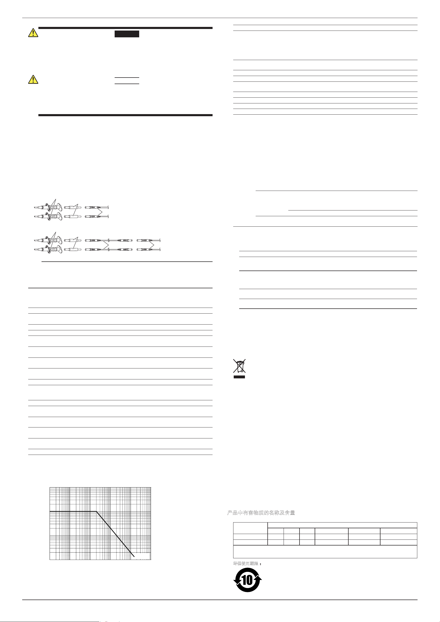
4 Frequency derating (load reduction) applies.
Derating of the input voltage by frequency
10000
1000
100
10
0.01 0.1 1 10 100
1000
Frequency [MHz]
Maximum input voltage [Vrms]
13.3 V
5 The accuracy depends on the vertical axis accuracy of the oscilloscope. It is the sum of the DC
gain accuracy and offset voltage.
6 Specification when the probe is used in combination with 100 Ω resistance adapters.
7 Specification when the probe is used in combination with 150 Ω resistance adapters and the
extension leads.

This manual suits for next models

1

Other YOKOGAWA Accessories manuals

YOKOGAWA FU24 User manual

YOKOGAWA

YOKOGAWA FU24 User manual

YOKOGAWA SX42 User manual

YOKOGAWA

YOKOGAWA SX42 User manual

YOKOGAWA PH8ERP User manual

YOKOGAWA

YOKOGAWA PH8ERP User manual

YOKOGAWA ISC40G(S) User manual

YOKOGAWA

YOKOGAWA ISC40G(S) User manual

YOKOGAWA DO72 User manual

YOKOGAWA

YOKOGAWA DO72 User manual

YOKOGAWA PH8ECP User manual

YOKOGAWA

YOKOGAWA PH8ECP User manual

YOKOGAWA SC4AJ Series User manual

YOKOGAWA

YOKOGAWA SC4AJ Series User manual

YOKOGAWA CT60 User manual

YOKOGAWA

YOKOGAWA CT60 User manual

YOKOGAWA Sushi Sensor XS770A User manual

YOKOGAWA

YOKOGAWA Sushi Sensor XS770A User manual

YOKOGAWA CT1000 User manual

YOKOGAWA

YOKOGAWA CT1000 User manual

YOKOGAWA ISC40FF User manual

YOKOGAWA

YOKOGAWA ISC40FF User manual

YOKOGAWA DO70G User manual

YOKOGAWA

YOKOGAWA DO70G User manual

YOKOGAWA DO30G User manual

YOKOGAWA

YOKOGAWA DO30G User manual

YOKOGAWA CT2000A User manual

YOKOGAWA

YOKOGAWA CT2000A User manual

YOKOGAWA DO71 User manual

YOKOGAWA

YOKOGAWA DO71 User manual

YOKOGAWA FU20-FTS User manual

YOKOGAWA

YOKOGAWA FU20-FTS User manual

YOKOGAWA FU20-MTS User manual

YOKOGAWA

YOKOGAWA FU20-MTS User manual

YOKOGAWA VZ20X User manual

YOKOGAWA

YOKOGAWA VZ20X User manual

YOKOGAWA CT1000 User manual

YOKOGAWA

YOKOGAWA CT1000 User manual

YOKOGAWA SC25V User manual

YOKOGAWA

YOKOGAWA SC25V User manual

YOKOGAWA SC41 User manual

YOKOGAWA

YOKOGAWA SC41 User manual

YOKOGAWA 90020B User manual

YOKOGAWA

YOKOGAWA 90020B User manual

YOKOGAWA Sushi Sensor XS530 User manual

YOKOGAWA

YOKOGAWA Sushi Sensor XS530 User manual

YOKOGAWA SC4A User manual

YOKOGAWA

YOKOGAWA SC4A User manual

Popular Accessories manuals by other brands

Valeport Hyperion 0901001 operating manual

Valeport

Valeport Hyperion 0901001 operating manual

mybaby slumberscents instruction manual

mybaby

mybaby slumberscents instruction manual

JUGS Z7300 owner's manual

JUGS

JUGS Z7300 owner's manual

ASCOM BS330 Technical Product Manual

ASCOM

ASCOM BS330 Technical Product Manual

KAMA MESTIC MCC-35 instruction manual

KAMA

KAMA MESTIC MCC-35 instruction manual

Siemens AP 257/42 Operating and mounting instructions

Siemens

Siemens AP 257/42 Operating and mounting instructions

Aeotec Water Sensor 7 Pro user guide

Aeotec

Aeotec Water Sensor 7 Pro user guide

ELCART TMR TC-100 quick start guide

ELCART

ELCART TMR TC-100 quick start guide

Caldwell 795234 Usage and Assembly Instructions

Caldwell

Caldwell 795234 Usage and Assembly Instructions

Wenglor FFAP Series user manual

Wenglor

Wenglor FFAP Series user manual

Skoda YETI - ACCESSORIES 2010 manual

Skoda

Skoda YETI - ACCESSORIES 2010 manual

Pilatech Reformer CS2 Manual of assembly and maintenance

Pilatech

Pilatech Reformer CS2 Manual of assembly and maintenance

Daikin KRCS01-8B installation manual

Daikin

Daikin KRCS01-8B installation manual

Lanaform Bali manual

Lanaform

Lanaform Bali manual

Hydac CS 1000 Series Operating and maintenance instructions

Hydac

Hydac CS 1000 Series Operating and maintenance instructions

DAVIS 6322C user manual

DAVIS

DAVIS 6322C user manual

Elsys ECO Series operating manual

Elsys

Elsys ECO Series operating manual

Vernier Go Direct Surface Temperature user manual

Vernier

Vernier Go Direct Surface Temperature user manual

manuals.online logo
manuals.online logoBrands
  • About & Mission
  • Contact us
  • Privacy Policy
  • Terms and Conditions

Copyright 2025 Manuals.Online. All Rights Reserved.