BGA 862
Guide to Using this Service Manual
This service manual contains the necessary safety
information, exploded drawings and instructions for
diagnosis and repairs. The graphic elements used in this
manual have the following meanings:
Supplements to this service manual
Technical information bulletins supplement the service
manual until a revised edition is issued.
–Always refer to the latest edition of the relevant parts
list for the part numbers of any replacement parts.
–Use the part numbers to identify the tools in the
"STIHL Special Tools" manual.
–None of these documents may be passed to third
parties.
Interactive video tutorial
Interactive video tutorials may be used for repair
procedures. They can be opened from the service
manual.
Your computer must meet the following requirements:
–Active internet connection
–HTML5 compatible internet browser
2.1 Basic Safety Measures
–Never use defective machines, housings or
analyzers.
–Use only original STIHL spare parts, batteries,
chargers and analyzers.
–Never insert objects into the cooling slots of batteries,
chargers and analyzers.
–Never short the contacts of the battery, charger or
analyzer with metallic objects.
Observe the national safety regulations in the instruction
manual.
Always switch off the machine and remove the battery
before performing any repairs or transporting the
machine.
WARNING
To reduce the risk of serious injury and serious burns,
observe the following points before performing any
repairs:
2.2 Battery
WARNING
Risk of injury from fluid escaping from battery.
–Avoid contact with the skin and eyes.
–In the event of contact, rinse affected area thoroughly
with water.
–Seek medical advice.
NUse and store the battery only in a temperature range
from -10°C up to max. + 50°C (14°F up to
max. 120°F).
2.3 Charger, STIHL ADG 1 Battery Analyzer and
STIHL ADG 2 Analyzer
NDo not cover the unit.
NConnect the charger/analyzer only to a power supply
with the voltage and frequency specified on the rating
plate.
NUse and store only in a temperature range from 5°C
up to max. + 40°C (40°F up to max. 105°F).
NIn the event of smoke or fire, disconnect unit from the
wall outlet immediately.
NDo not operate the unit in a hazardous, easily
combustible location.
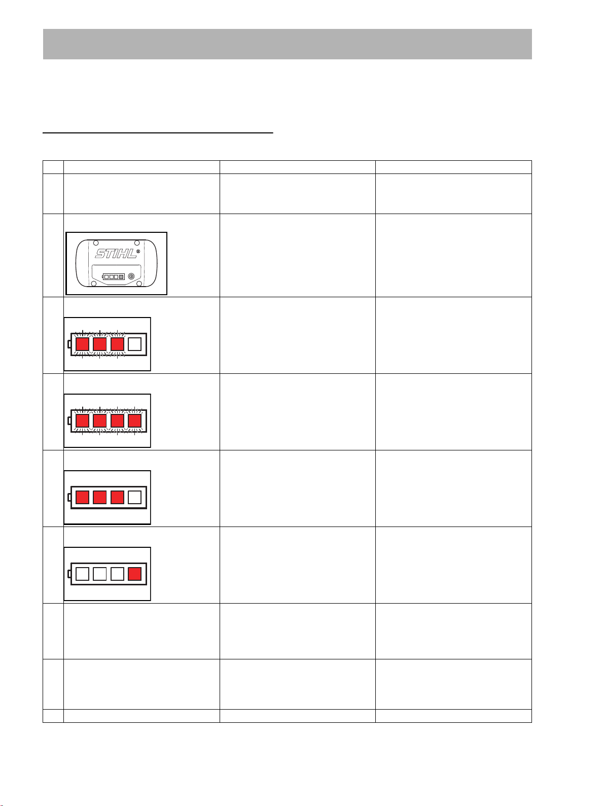
1 Safe diagnosis and repairs
Action to be taken
Reference to another chapter, i.e. chapter 3 in
this example
Interactive video tutorial available for this
chapter
Tighten screw to torque specified, i.e. 3 Nm in
this example
Tighten screw to torque specified, i.e. 5 Nm in
this example; then back it off 1 turn
counterclockwise
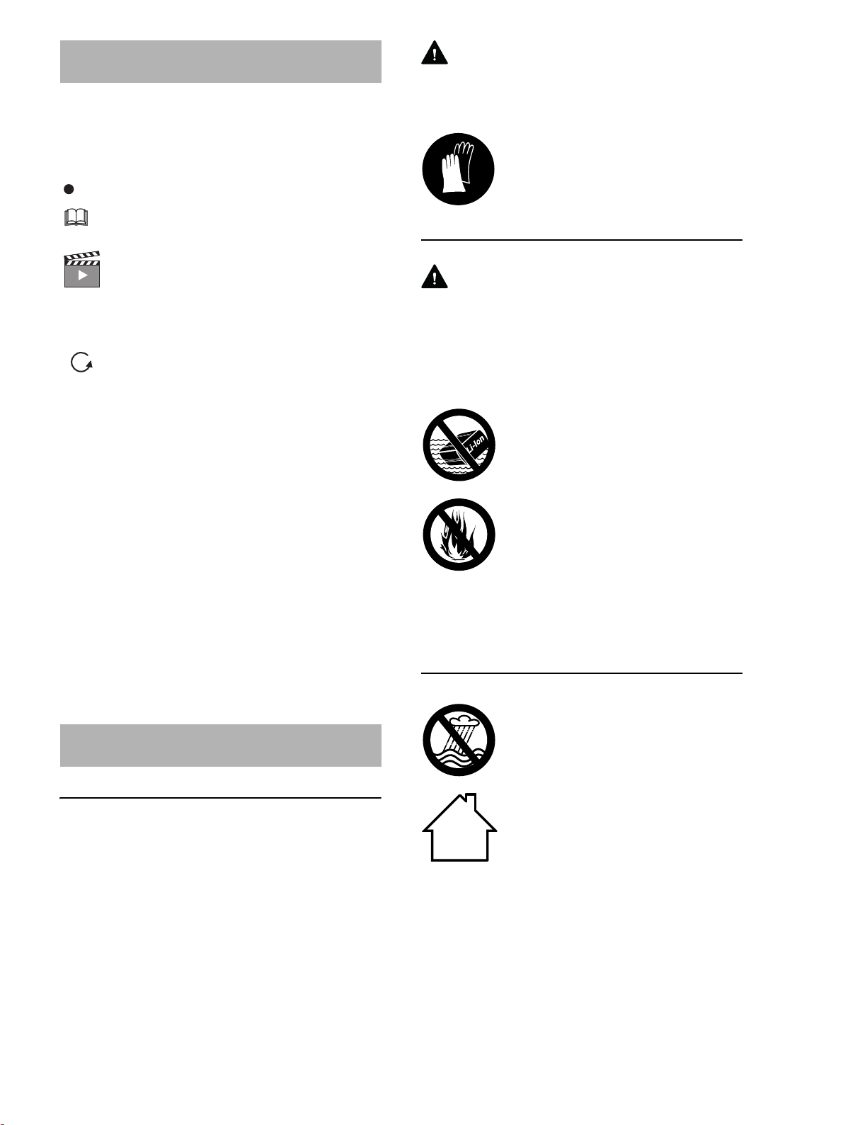
2 Safety Precautions
Always wear protective gloves when work-
ing on sharp or hot components.
Do not immerse the battery in liquids – this
may cause a malfunction or thermal reac-
tion – risk of explosion.
Protect from heat, fire and direct sunlight –
risk of explosion and fire.
Protect from dampness.
Use and store only indoors in dry
locations.