Stihl SR 200 User manual

Contents
1 Guide to Using this Manual.........................2
2 Safety Precautions and Working Techni‐
ques............................................................ 2
3 Assembling the Unit.................................... 8
4 Adjusting the Throttle Cable........................9
5 Harness.....................................................10
6 Fuel........................................................... 10
7 Fueling...................................................... 11
8 Information Before You Start.................... 12
9 Starting / Stopping the Engine.................. 13
10 Operating Instructions...............................14
11 Calculating Required Quantity of Solution
.................................................................. 15
12 Metering Unit.............................................16
13 Filling the Container.................................. 17
14 Mistblowing............................................... 18
15 After Finishing Work..................................19
16 Storing the Machine.................................. 19
17 Cleaning the Air Filter............................... 19
18 Adjusting the Carburetor........................... 20
19 Catalytic Converter................................... 20
20 Spark Plug................................................ 20
21 Engine Running Behavior......................... 21
22 Maintenance and Care..............................21
23 Minimize Wear and Avoid Damage...........22
24 Main Parts.................................................23
25 Specifications............................................24
26 Maintenance and Repairs......................... 25
27 Disposal.................................................... 25
28 EC Declaration of Conformity................... 25
Dear Customer,
Thank you for choosing a quality engineered
STIHL product.
It has been built using modern production techni‐
ques and comprehensive quality assurance.
Every effort has been made to ensure your satis‐
faction and trouble-free use of the product.
Please contact your dealer or our sales company
if you have any queries concerning this product.
Your
Dr. Nikolas Stihl
1 Guide to Using this Manual
1.1 Pictograms
The meanings of the pictograms attached to the
machine are explained in this manual.
Depending on the model concerned, the follow‐
ing pictograms may be attached to your
machine.
Fuel tank; fuel mixture of gasoline
and engine oil
Operate manual fuel pump
Solution feed
1.2 Symbols in text
WARNING
Warning where there is a risk of an accident or
personal injury or serious damage to property.
NOTICE
Caution where there is a risk of damaging the
machine or its individual components.
1.3 Engineering improvements
STIHL's philosophy is to continually improve all
of its products. For this reason we may modify
the design, engineering and appearance of our
products periodically.
Therefore, some changes, modifications and
improvements may not be covered in this man‐
ual.
2 Safety Precautions and
Working Techniques
Special safety precautions must be
observed when working with the
power tool.
It is important you read and under‐
stand the User Manual before com‐
missioning and keep it in a safe place
for future reference. Non-compliance
with the User Manual may cause seri‐
ous or even fatal injury.
Observe all applicable local safety regulations,
e.g. by trade organizations, social insurance
institutions, labor safety authorities etc.
If you have not used this machine before: Have
your dealer or other experienced user show you
English
2 0458-457-0121-C
© ANDREAS STIHL AG & Co. KG 2022
0458-457-0121-C. VA1.M21.
Printed on chlorine-free paper
Printing inks contain vegetable oils, paper can be recycled.
Original Instruction Manual
0000008750_004_GB

how to handle your machine safely or attend a
specialist course.
Minors must never work with the machine –
except for young people over the age of 16 who
are being trained under supervision.
Children, animals and bystanders must not be
allowed near the machine.
When the machine is not in use, put it in a place
where it does not endanger others. Secure the
machine against unauthorized access.
The user is responsible for accidents or risks
involving third parties or their property.
Do not pass on or lend the machine to persons
who are not familiar with this model and its han‐
dling – always include the User Manual.
The use of machines that emit noise may be limi‐
ted to certain hours of the day as specified by
national and/or regional or local regulations.
Do not operate your machine if any of its compo‐
nents are damaged. Pay special attention to the
tightness of the container (no leaks).
Operate the power tool only if it is complete and
properly assembled.
Do not use a high-pressure washer to clean the
power tool. The solid jet of water may damage
parts of the unit.
2.1 Physical fitness
To operate the power tool you must be rested, in
good physical condition and mental health. If you
have any condition which may be aggravated by
strenuous work, check with your doctor before
operating a power tool.
If you have a pacemaker: The ignition system of
your machine produces an electromagnetic field
of very low intensity. This field may interfere with
some pacemakers. To reduce health risks,
STIHL recommends that persons with pacemak‐
ers consult their physician and the pacemaker
manufacturer before operating this tool.
Do not operate the power tool if you are under
the influence of any substance (drugs, alcohol)
which might impair vision, dexterity or judgment.
2.2 Applications
This mistblower is suitable for applying fungi‐
cides, herbicides and pesticides at ground level.
Spraying overhead is possible with mistblowers
equipped with a pressure pump. Typical areas of
application are in fruit, vegetable, wine and crop
growing, plantations, flower growing, grassland
and forestry.
Only use plant protection products that are spe‐
cifically approved for use in portable mistblowers.
Do not use your power tool for any other purpose
because of the increased risk of accidents and
damage to the power tool. The product must not
be modified in any way - this may also lead to
accidents or damage to the unit.
2.3 Accessories and replacement
parts
Only use parts and accessories that are explicitly
approved for this power tool by STIHL or are
technically identical. If you have any questions in
this respect, consult your dealer. Use only high
quality parts and accessories in order to avoid
the risk of accidents and damage to the unit.
STIHL recommends the use of original STIHL
parts and accessories. They are specifically
designed to match the product and meet your
performance requirements.
Never attempt to modify your power tool in any
way since this may increase the risk of personal
injury. STIHL excludes all liability for personal
injury and damage to property caused while
using unauthorized attachments.
2.4 Clothing and equipment
Wear proper protective clothing and equipment
when using, filling and cleaning the power tool.
Follow the chemical manufacturer's user manual
with respect to protective equipment.
Immediately change work clothes contaminated
with plant control chemicals.
Clothing must be snug-fitting but
allow complete freedom of move‐
ment.
For some plant control chemicals it is
necessary to wear impermeable cov‐
eralls.
If you are spraying overhead, wear impermeable
head covering.
Avoid any clothing, scarves, neckties,
jewelry or anything that could get into
the air intake. Tie up and confine long
hair above your shoulders so that it
cannot be pulled into the machine.
2 Safety Precautions and Working Techniques English
0458-457-0121-C 3

Wear impermeable safety boots with
a non-slip sole which are resistant to
plant protection products.
Do not wear sandals or go barefoot.
WARNING
To reduce the risk of eye injuries,
wear close-fitting safety glasses in
accordance with European Standard
EN 166. Make sure the safety
glasses are a snug fit.
Wear a suitable respirator.
Wear "personal" sound protection, e.g. ear
defenders.
Breathing plant control chemicals may endanger
your health. Always wear a suitable respirator to
protect yourself against health risks and allergic
reactions. Observe warnings in the user manual
of the plant protection product and all applicable
local safety regulations, standards and ordinan‐
ces.
Wear impermeable gloves resistant to
plant control chemicals.
2.5 Handling Plant Control Chemi‐
cals
Read the user manual supplied with the plant
protection chemical prior to use. Follow the
instructions with respect to mixing, using, per‐
sonal protective equipment, storage and dis‐
posal.
Observe the legal requirements for handling
plant protection products.
Plant protection chemicals may contain substan‐
ces that are harmful to humans, animals, plants
and the environment – risk of poisoning and risk
of serious or fatal injuries!
Plant protection chemicals may be used only by
persons trained in their handling and the appro‐
priate first-aid measures.
Keep the user manual or label of the plant con‐
trol chemical available at all times in order to
inform the doctor about the chemical concerned
in an emergency. In an emergency, follow the
chemical manufacturer's instructions provided or
on the label.
2.5.1 Mixing the Spray Solution
Mix the plant protection product strictly in accord‐
ance with the manufacturer's instructions – incor‐
rect mixtures may produce toxic fumes or explo‐
sive solutions.
–Never spray liquid plant control chemicals
undiluted
–Mix the solution outdoors only or in well-venti‐
lated locations
–Only prepare sufficient solution for the job on
hand so that nothing is left over
–Mix different chemicals only in accordance
with the manufacturer's instructions – incorrect
mixtures may produce toxic fumes or explo‐
sive solutions
–Do not mix different plant protection products
unless such a mixture is approved by the man‐
ufacturer
2.5.2 Filling the Container
–Fill the container with plant protection products
outdoors only or in well-ventilated locations
–Stand the power tool on a level surface – do
not fill the container above the maximum mark
–To reduce the risk of injury, do not fill the
power tool while wearing it on your back.
–Only fill up with sufficient solution for the job
on hand so that nothing is left over
–Close the valve lever before filling
–When filling from central water supply, do not
immerse the end of the hose in the solution –
sudden low pressure in the system may cause
the solution to be sucked back into the water
supply
–Before filling the container with spray solution,
carry out test run with fresh water and check
all parts of the sprayer for leaks
–After filling, fit the filler cap and tighten it down
firmly
2.5.3 Use
–Work only in the open or in very well ventilated
locations, e.g. open greenhouses
–Do not eat, drink or smoke while working with
plant protection chemicals
–Never blow through nozzles or other compo‐
nents by mouth
–Avoid contact with plant control chemicals –
immediately change clothing contaminated
with plant control chemical
–Do not spray in windy conditions
Unfavorable weather conditions may result in an
incorrect concentration of the plant protection
product. Overdosing may damage plants and the
environment. Under-dosing may result in unsuc‐
cessful plant treatment.
English 2 Safety Precautions and Working Techniques
4 0458-457-0121-C

In order to reduce the risk of damage to the envi‐
ronment and plants, do not operate the sprayer:
–in windy conditions
–at temperatures above 25°C in the shade
–in direct sunlight
In order to reduce the risk of accidents and dam‐
age to the power tool, never operate the power
tool with:
–flammable liquids
–viscous or sticky liquids
–caustic or corrosive chemicals
–liquids hotter than 50 °C
2.5.4 Bearing
–During work breaks, do not leave the sprayer
in the hot sun or near any heat source
–Do not store spray solution in the container for
longer than one day
–Store and transport plant protection products
only in approved containers
–Never store the plant protection products in
containers intended for foods, drinks or animal
feed
–Do not store plant protection products with
foods, drinks or animal feed
–Keep plant protection products out of the
reach of children and animals
–Store the power tool empty and clean
–Store plant protection products and power tool
in a place secured against unauthorized use
–Store plant protection products and power tool
in a dry place protected from frost
2.5.5 Disposal
Never dispose of residual plant protection prod‐
ucts or contaminated rinsing solutions in water‐
ways, drains, sewers, street gutters or manholes.
–Dispose of residual chemicals and used con‐
tainers in accordance with local waste dis‐
posal regulations
2.6 Transporting the machine
Always stop the engine.
Transporting in a vehicle:
–Secure the machine against overturning, dam‐
age and fuel spillage
–The container must be empty and clean
2.7 Refueling
Gasoline is extremely flammable –
keep it away from naked flames – do
not spill any fuel – no smoking.
Always shut off the engine before refueling.
Do not fuel a hot engine – fuel may spill and
cause a fire.
Always remove the power tool from your back
and put it on the ground before refueling. Fuel
the machine only when it is standing on the
ground.
Open the fuel cap carefully to allow any pressure
build-up in the tank to release slowly and avoid
fuel spillage.
Only refuel the machine in a well ventilated
place. If you spill fuel, wipe the machine immedi‐
ately – if fuel gets on your clothing, change
immediately.
Check for fuel leakage! Never start
the engine if fuel has been spilled or
is leaking – Fatal burns may result!
Fuel cap
Never use a tool to open or close the screw-type
fuel cap. This could damage the cap and cause
fuel to leak out.
After fueling, tighten down the screw-
type fuel cap as securely as possible.
2.8 Before starting
Check that your power tool is properly assem‐
bled and in good condition, especially if it has
been subjected to unusually high loads for which
it was not designed (e.g. heavy impact or a fall).
–Check the fuel system for leaks, especially the
visible parts, e. g., fuel cap, hose connections,
manual fuel pump (only in machines with a
manual fuel pump). In case of leakage and
damage, do not start the engine – risk of fire!
Have the machine serviced by a dealer before
using it
–The setting lever must move easily to STOP or
0
–Throttle trigger must move freely and spring
back by itself to the idle position
–The blower tubes must be properly assembled
–Keep the handles dry and clean – free from oil
and dirt – this is important for safe control of
the machine
–Check that the spark plug boot is secure – a
loose boot may cause sparking that could
ignite combustible fumes and cause a fire!
–Check the fuel system for leaks
–Check the condition and tightness of con‐
tainer, hose and metering unit
2 Safety Precautions and Working Techniques English
0458-457-0121-C 5

–Check condition of harness straps and replace
damaged or worn straps
–Check the condition of the blower housing
Wear of the blower housing (cracks, nicks, chips)
may result in an increased risk of injury from
thrown foreign objects. If the blower housing is
damaged, consult your dealer – STIHL recom‐
mends you contact a STIHL servicing dealer
To reduce the risk of accidents and personal
injury, do not operate your power tool if it is not
properly assembled and in good condition.
271BA003 KN
For emergencies: Practice quickly opening the
fastener on the waist belt (special accessory),
loosening the shoulder straps and setting down
the unit. To avoid damage, do not throw the unit
to the ground when practicing.
2.9 Starting the engine
Start the engine at least 3 meters from the fuel‐
ing spot, outdoors only.
Your power tool is designed to be operated by
one person only. Do not allow other persons in
the work area – even when starting.
Always proceed as described in the user manual.
Place the machine on level ground only, ensure
that you have a secure footing and hold the
machine securely.
If an assistant is required to put the power tool
on your back, make sure that
–the engine is running at idle speed
–the assistant is not standing in the area of the
exhaust outlet and breathing exhaust fumes
–the valve lever is closed
–the assistant is not standing in the area of the
outlet nozzle
–the assistant leaves the work area immedi‐
ately after you have put the power tool on your
back
2.10 Holding and guiding the
machine
0002BA084 KN
Carry the power tool on your back with both har‐
ness straps – do not hang it over one shoulder.
Hold and control the blower tube with your right
hand on the control handle – even if you are left-
handed.
Work only slowly, moving in a forwards direction
– always observe the discharge area of the
blower tube – do not move backwards – risk of
tripping!
Keep the power tool and container upright. To
avoid the risk of chemical leaking from the con‐
tainer and causing injury,do not bend forwards.
2.11 While working
Do not direct the blower tube at bystanders since
the air flow can blow small objects at great
speed.
In the event of impending danger or in an emer‐
gency, switch off the engine immediately by mov‐
ing the setting lever to STOP or 0.
Never leave a running machine unattended.
Take special care in slippery conditions – damp‐
ness, snow, ice, on slopes or uneven ground.
Watch out for obstacles: Be careful of refuse,
tree stumps, roots and ditches which could
cause you to trip or stumble.
Be particularly alert and cautious when wearing
hearing protection because your ability to hear
warnings (shouts, alarms, etc.) is restricted.
English 2 Safety Precautions and Working Techniques
6 0458-457-0121-C

Take breaks when you start getting tired or feel‐
ing fatigue – risk of accidents!
Work calmly and carefully – in daylight conditions
and only when visibility is good. Proceed with
caution, do not put others in danger.
Do not work on a ladder or in unstable locations.
When working in open ground and gardens take
special care to avoid harming small animals.
To reduce the risk of electrocution, never operate
this power tool in the vicinity of live wires or
power cables.
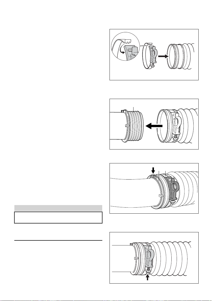
Always clean the spray container and hose sys‐
tem before changing to a different plant protec‐
tion product.
As soon as the engine is running, the
power machine generates toxic
exhaust gas. These gases may be
odorless and invisible and may con‐
tain unburned hydrocarbons and ben‐
zene. Never work with the machine in
closed or poorly ventilated rooms.
To reduce the risk of serious or fatal injury from
breathing toxic fumes, ensure proper ventilation
when working in trenches, hollows or other con‐
fined locations.
Stop work immediately if you start suffering from
nausea, headaches, impaired vision (e.g. your
field of vision gets smaller), impaired hearing,
dizziness, or impaired concentration – these
symptoms may possibly be the result of too-high
exhaust gas concentration – Risk of accidents!
Operate your power tool so that it produces a
minimum of noise and emissions – do not run the
engine unnecessarily, accelerate the engine only
when working.
To reduce the risk of fire, do not smoke while
operating or standing near your power tool. Com‐
bustible fuel vapor may escape from the fuel sys‐
tem.
If your power tool is subjected to unusually high
loads for which it was not designed (e.g. heavy
impact or a fall), always check that it is in good
condition before continuing work – see also
"Before Starting". Check in particular that the fuel
system has no leaks and the safety equipment is
fully operative. Do not continue operating your
power tool if it is damaged. In case of doubt, con‐
tact a dealer.
2.12 After finishing work
Close the valve lever
Always shut off the engine before taking the
power tool off your back.
After finishing work, put the power tool down on
a level, non-flammable surface. Do not place the
machine near easily flammable materials (e.g.
wood chips, bark, dry grass, fuel) – risk of fire!
Check all parts of the power tool for leaks.
After finishing work, thoroughly clean the power
tool and wash your hands, face and, if neces‐
sary, your clothes.
Keep other persons and animals away from the
areas that have been sprayed and do not walk
on them until the plant protection chemical has
dried.
2.13 Vibrations
Prolonged use of the power tool may result in
vibration-induced circulation problems in the
hands (whitefinger disease).
No general recommendation can be given for the
length of usage because it depends on several
factors.
The period of usage is prolonged by:
–Hand protection (wearing warm gloves)
–Work breaks
The period of usage is shortened by:
–Any personal tendency to suffer from poor cir‐
culation (symptoms: frequently cold fingers,
tingling sensations).
–Low outside temperatures.
–The force with which the handles are held (a
tight grip restricts circulation).
Continual and regular users should monitor
closely the condition of their hands and fingers. If
any of the above symptoms appear (e.g. tingling
sensation in fingers), seek medical advice.
2.14 Maintenance and Repairs
Service the machine regularly. Do not attempt
any maintenance or repair work not described in
the instruction manual. Have all other work per‐
formed by a servicing dealer.
STIHL recommends that you have servicing and
repair work carried out exclusively by an author‐
ized STIHL servicing dealer. STIHL dealers are
regularly given the opportunity to attend training
courses and are supplied with the necessary
technical information.
Only use high-quality replacement parts in order
to avoid the risk of accidents and damage to the
2 Safety Precautions and Working Techniques English
0458-457-0121-C 7

machine. If you have any questions in this
respect, consult a servicing dealer.
STIHL recommends the use of genuine STIHL
replacement parts. They are specifically
designed to match your model and meet your
performance requirements.
To reduce the risk of injury, always shut off the
engine before carrying out any maintenance or
repairs or cleaning the machine. – Exception:
Carburetor and idle speed adjustments.
Do not turn the engine over on the starter with
the spark plug boot or spark plug removed since
there is otherwise a risk of fire from uncontained
sparking.
Do not service or store your machine near open
flames.
Check the fuel filler cap for leaks at regular inter‐
vals.
Use only a spark plug of the type approved by
STIHL and make sure it is in good condition –
see "Specifications".
Inspect the ignition lead (insulation in good con‐
dition, secure connection).
Check the condition of the muffler.
To reduce the risk of fire and damage to hearing,
do not operate your machine if the muffler is
damaged or missing.
Do not touch a hot muffler since burn injury will
result.
Vibration behavior is influenced by the condition
of the AV elements – check the AV elements at
regular intervals.
Shut off the engine before rectifying problems.
3 Assembling the Unit
NOTICE
The solution hose and throttle cable are already
connected and must not be kinked while assem‐
bling the machine.
The combination wrench and screwdriver are in
the supplied accessory bag.
3.1 Fitting the pleated hose on the
elbow
12
9928BA001 AM
► Open the hose clamp (1) and fit it on the plea‐
ted hose (2).
► Engage the tab in the recess.
3
2
2431BA017 KN
► Push the pleated hose (2) over the slip ring (3)
as far as stop.
31
2431BA002 KN
► Line up the hose clamp (1) and slip ring (3):
–the two lugs (arrow) on the slip ring face up.
–The hose clamp's hook faces outwards.
9928BA019 AM
English 3 Assembling the Unit
8 0458-457-0121-C

► Tighten down the screw (arrow).
3.2 Mounting the Control Handle
3
2431BA003 KN
1
2
► Open up the control handle (1) with liner (2)
and push it over the stub (3) of the pleated
hose.
5
4
2431BA004 KN
► Attach throttle cable to retainer (4).
► Secure hose with retainer (5) to third pleat
(arrow) in pleated hose.
3.3 Mounting the Blower Tube and
Nozzle
4
3
2
2431BA005 KN
1
► Push the blower tube (1) into the stub of plea‐
ted hose (2) as far as the stop.
► Push the nozzle (3) onto blower tube as far as
stop – metering knob (4) must be in line with
the control handle.
3.4 Adjusting and Securing the
Control Handle
► Put the machine on your back and adjust the
harness – see "Harness".
2
2431BA006 KN
a
1
► Slide the control handle (1) along the tube to
the most comfortable position – distance
between nozzle outlet (2) and the control han‐
dle (1) must be at least 500 mm (20 in) (a).
1
2431BA018 KN
3
► Secure the hose clamp (1) with the screw (3).
4 Adjusting the Throttle
Cable
It may be necessary to correct the adjustment of
the throttle cable after assembling the machine
or after a prolonged period of operation.
Adjust the throttle cable only when the unit is
completely and properly assembled.
0002BA013 KN
► Set throttle trigger to the full throttle position –
as far as stop.
► Carefully rotate the screw in the throttle trigger
in the direction of the arrow until you feel initial
resistance. Then rotate it another full turn.
4 Adjusting the Throttle Cable English
0458-457-0121-C 9

5 Harness
5.1 Adjusting the Harness
373BA003 KN
► Pull the ends of the straps downwards to
tighten the harness.
► Adjust the harness so that the backplate fits
snugly and securely against your back.
5.2 Loosening the Harness
373BA004 KN
► Lift the tabs of the sliding adjusters.
6 Fuel
The engine requires a mixture of gasoline and
engine oil.
WARNING
Avoid direct skin contact with fuel and breathing
in of gasoline fumes.
6.1 STIHL MotoMix
STIHL recommends using STIHL MotoMix. This
pre-blended fuel is free of benzene and lead, is
distinguished by a high octane rating, and
always provides the proper mixing ratio.
STIHL MotoMix uses STIHL HP Ultra two-stroke
engine oil for optimum engine life.
MotoMix is not available in all markets.
6.2 Mixing fuel
NOTICE
Unsuitable fuels or a mixing ratio that deviates
from the specification can lead to severe engine
damage. The engine, seals, fuel lines and fuel
tank may be damaged if low-quality gasoline or
engine oil is used.
6.2.1 Gasoline
Use only high-quality gasoline with an octane rat‐
ing of at least 90 ROC – leaded or unleaded.
Gasoline with an alcohol component exceeding
10% can cause impaired engine performance in
engines with manually adjustable carburetors
and thus should not be used in these engines.
Engines with M-Tronic deliver full engine per‐
formance using gasoline with an alcohol compo‐
nent of up to 27% (E27).
6.2.2 Engine oil
If you mix the fuel yourself, use only STIHL two-
stroke engine oil or another high-performance
engine oil classified as JASO FB, JASO FC,
JASO FD, ISO-L-EGB, ISO-L-EGC or ISO-L-
EGD.
STIHL specifies STIHL HP Ultra two-stroke
engine oil or an equivalent high-performance
engine oil in order to maintain emission limits
over the machine’s service life.
6.2.3 Mixing ratio
with STIHL two-stroke engine oil 1:50; 1:50 =
1 part oil + 50 parts gasoline
6.2.4 Examples
Quantity of gaso‐
line
STIHL two-stroke
engine oil 1:50
Liters Liters (ml)
1 0.02 (20)
5 0.10 (100)
10 0.20 (200)
15 0.30 (300)
20 0.40 (400)
25 0.50 (500)
► Pour oil into an approved safety fuel canister
first, then add gasoline and mix thoroughly
6.3 Storing fuel mixture
Store in approved safety fuel canisters only in a
dry, cool and secure place protected against light
and sunlight.
English 5 Harness
10 0458-457-0121-C

Fuel mixture deteriorates with age – mix only as
much as needed for a few weeks. Do not store
fuel mixture for longer than 30 days. The fuel
mixture can become unusable more quickly if
exposed to light, sunlight or low or high tempera‐
tures.
STIHL MotoMix however can be stored for up to
5 years without any problems.
► Shake the canister containing the fuel mixture
thoroughly before refueling
WARNING
Pressure may have built up in the canister –
open it carefully.
► The fuel tank and the canister in which fuel
mixture is stored should be cleaned thoroughly
from time to time
Residual fuel and the liquid used for cleaning
must be disposed of in accordance with regula‐
tions and without harming the environment!
7 Fueling
7.1 Preparations
9928BA018 AM
► Before fueling, clean the filler cap and the area
around it to ensure that no dirt falls into the
tank.
7.2 Opening screw-type tank cap
002BA447 KN
► Turn the cap counterclockwise until it can be
removed from the tank opening.
► Remove the cap.
7.3 Filling up with fuel
Take care not to spill fuel while fueling and do
not overfill the tank. STIHL recommends you use
the STIHL filler nozzle (special accessory).
7.4 Closing screw-type tank cap
002BA448 KN
► Place the cap in the opening.
► Turn the cap clockwise as far as stop and
tighten it down as firmly as possible by hand.
7 Fueling English
0458-457-0121-C 11

8 Information Before You
Start
NOTICE
With the engine stopped and before starting,
check the air intakes between the backplate and
powerhead for blockages and clean if necessary.
8.1 Control handle
1
0002BA017 KN
23
1 Setting lever
2 Throttle trigger
3Throttle trigger lockout 1)
8.2 Functions of setting lever
Run position F
Engine runs or is ready to start. Throttle trig‐
ger (2) can be moved to any position.
Stop position 0
Ignition is interrupted, engine stops. The setting
lever (1) is not locked in this position. It springs
back to the run position. The ignition is again
ready for operation.
Throttle trigger limiter position 1)
Travel of throttle trigger can be limited in two
stages:
2431BA019 KN
a
b
1
a 1/3 throttle
b 2/3 throttle
To disengage the travel limiter,
► Return the setting lever (1) to the run posi‐
tion F.
Throttle lock 1)
2431BA008 KN
2
1
The throttle trigger (2) can be locked in any
required position.
To disengage the lock:
► Return the setting lever (1) to the run posi‐
tion F.
1) Not in all versions, country-specific
English 8 Information Before You Start
12 0458-457-0121-C

9 Starting / Stopping the
Engine
9.1 Before Starting
0002BA060 KN
1
► Close valve lever (1) for solution feed.
9.2 Start the engine.
► Observe safety precautions.
NOTICE
Start your unit on a clean, dust-free surface only
to ensure that no dust is sucked in.
0002BA019 KN
►The setting lever must be on F
9928BA006 AM
► Press the manual fuel pump bulb at least five
times – even if the bulb is filled with fuel.
Cold Engine (cold start)
9928BA007 AM
►Turn the choke knob to g.
Warm Engine (warm start)
9928BA008 AM
►Turn the choke knob to <.
Also use this setting if the engine has been run‐
ning but is still cold.
Cranking
2431BA009 KN
9 Starting / Stopping the Engine English
0458-457-0121-C 13

► Place the unit securely on the ground and
make sure that bystanders are well clear of
the nozzle outlet.
► Make sure you have a firm footing: Hold the
unit with your left hand on the container and
put one foot against the base plate to prevent
it from slipping.
► Pull the starter grip slowly with your right hand
until you feel it engage and then give it a brisk
strong pull. Do not pull out the starter rope to
full length – it might otherwise break.
► Do not let the starter grip snap back. Guide it
slowly back into the housing so that the starter
rope can rewind properly.
► Continue cranking until the engine runs.
9.3 Other Hints on Starting
9.3.1 If the engine stops while the choke
knob in on g or during acceleration
►Move the choke knob to < and continue
cranking until the engine runs.
9.3.2 If engine does not start
► Make sure all settings are correct (choke
knob, setting lever in run position F).
► Repeat the starting procedure.
9.3.3 If fuel tank has been run completely
dry and then refueled
9928BA006 AM
► Press the manual fuel pump bulb at least five
times – even if the bulb is filled with fuel.
9.4 As soon as the engine runs
2431BA010 KN
► Operate the throttle trigger.
► Choke knob automatically returns to the run
position F when the throttle trigger is operated.
9.4.1 At very low outside temperatures
► Open throttle slightly – warm up the engine for
a short period.
9.5 Stopping the Engine
0002BA025 KN
► Move the setting lever in the direction of 0 –
the engine stops – the setting lever springs
back to the on position.
10 Operating Instructions
10.1 During Operation
After a long period of full throttle operation, allow
the engine to run for a short while at idle speed
so that engine heat can be dissipated by the flow
of cooling air. This helps protect engine-mounted
English 10 Operating Instructions
14 0458-457-0121-C

components (ignition, carburetor) from thermal
overload.
10.2 After Finishing Work
Storing for a short period: Wait for the engine to
cool down. Keep the machine in a dry place, well
away from sources of ignition, until you need it
again. For longer out-of-service periods – see
"Storing the Machine".
11 Calculating Required
Quantity of Solution
11.1 Determining surface area (m2)
In the case of ground crops, simply multiply the
length of the field by its width.
The surface area of high-growing plants is calcu‐
lated approximately by measuring the length of
the rows and the average height of the foliage.
The result is multiplied by the number of rows
and then by two if both sides have to be treated.
The surface area in hectares is obtained by
dividing the number of square meters by 10,000.
Example:
A field 120 meters long and 30 meters wide has
to be treated with a pesticide.
Area:
120 m x 30 m = 3,600 m2
3,600 / 10,000 = 0.36 ha
11.2 Determining quantity of active
ingredient
Refer to the instructions supplied with the active
ingredient to determine:
–Required quantity of active ingredient for 1
hectare (ha).
–Concentration of active ingredient (mix ratio).
Multiply the required quantity of active ingredient
for 1 hectare by the area determined in hectares.
The result is the quantity of active ingredient
required for the area to be treated.
Example:
According to the maker’s instructions, 0.4 liters of
active ingredient are required per hectare to
obtain a concentration of 0.1%.
Quantity of active ingredient:
0.4 (l/ha) x 0.36 (ha) = 0.144 l
11.3 Determining quantity of solution
The quantity of solution required is calculated as
follows:
TWx 100 = TB
K
TW = Quantity of active ingredient in liters
K K = Concentration in %
TB = Required quantity of solution in liters
Example:
The calculated quantity of active ingredient is
0.144 liters. According to the maker’s instruc‐
tions, the concentration is 0.1%.
Quantity of solution:
0.144 l x 100 = 144 l
0.1 %
11.4 Determining walking speed
Carry out a trial run with the machine fueled and
the container filled with water. Operate the spray
tube (swing it back and forth) as for the real run
described below. Determine the distance walked
in one minute.
Also use the trial run to check the selected work‐
ing width. The best working width for low-growing
crops is 4–5 m. Mark the working width with
stakes.
Dividing the distance walked in meters by the
time in minutes gives you the walking speed in
meters per minute (m/min).
Example:
The distance covered in one minute is 10
meters.
Walking speed:
10 m = 10 m/min
1 min
11.5 Determining discharge rate
The setting of the metering unit is calculated as
follows:
Va(l) x vb(m/min) x b(m) = Vc(l/min)
A (m2)
Va = Quantity of solution
vb = Walking speed
Vc = Discharge rate
11 Calculating Required Quantity of Solution English
0458-457-0121-C 15

b = Working width
A = Area
Example:
The values determined above and a working
width of 4 meters require the following setting on
the metering unit:
144 l x 10 (m/min) x 4 m = 1.6 l/min
3600 m2
Hectares (ha) have to be converted into m2 (ha x
10,000 = m2).
To adjust the required discharge rate see "Meter‐
ing Unit".
12 Metering Unit
12.1 Valve Lever
1
0002BA061 KN
A
B
1
Solution feed is started and stopped with the
valve lever (1).
► Position A (valve lever vertical, up) – open
► Position B (valve lever horizontal, down) –
closed
12.2 Metering Knob
2
1
2431BA022 KN
► Rotate the metering knob (1) for infinitely vari‐
able discharge rate
Position 1 = minimum flow rate
Position 6 = maximum flow rate
The numbers on the metering knob must be lined
up with the lug (2) under the knob.
12.3 Discharge Rate
0811BA019 KN
The discharge rate (l/min) depends on the meter‐
ing knob setting and the spray tube angle.
12.3.1 Discharge rate (l/min) without pressure
pump
Spray tube angle
Knob set‐
ting
- 30° 0° + 30
°
1 0.24 0.17 0.11
2 0.82 0.66 0.46
3 1.42 1.13 0.84
4 2.2 1.66 1.1
5 2.69 2.13 1.46
6 2.91 2.25 1.52
English 12 Metering Unit
16 0458-457-0121-C

12.3.2 Discharge rate (l/min) without pressure
pump, with ULV nozzle
Spray tube angle
Knob set‐
ting
- 30° 0° + 30
°
0.5 0.05 0.04 0.03
0.65 0.08 0.07 0.05
0.8 0.12 0.09 0.08
12.3.3 Discharge rate (l/min) with pressure
pump (special accessory)
Spray tube angle
Knob set‐
ting
- 30° 0° + 30
°
1.0 0.64
1.6 1.7
2.0 2.59
12.3.4 Discharge rate (l/min) with pressure
pump (special accessory) and ULV
nozzle
Spray tube angle
Knob set‐
ting
- 30° 0° + 30
°
0.5 0.15
0.65 0.2
0.8 0.37
12.4 Checking Flow Rate
► Place the unit on the ground.
► Fill the container with water up to 10 liter mark.
Machines without pressure pump
► Set the "standard" metering knob to 6.
► Start the machine.
► Hold the spray tube horizontally, run the
engine at full throttle, spray the contents of the
container down to the 5 liter mark and note the
time taken.
The time required to spray 5 liters fluid should be
between 110 and 150 seconds.
Machines with pressure pump (special acces‐
sory)
► Fit metering knob 2.0 in the nozzle.
► Start the machine.
► Hold the spray tube horizontally, run the
engine at full throttle, spray the contents of the
container down to the 5 liter mark and note the
time taken.
The time required to spray 5 liters fluid should be
between 100 and 130 seconds.
In case of deviations:
► Check the container, hose system, metering
knob and optional pressure pump for contami‐
nation and clean if necessary.
► Check blower air intake and clean if neces‐
sary.
► Check engine setting and correct if necessary.
If there is no improvement, contact your dealer
for assistance.
13 Filling the Container
► Turn the cap counterclockwise until it can be
removed from the container opening.
2431BA021 KN
1
► The gasket (1) in the cap must be in good con‐
dition and clean.
► Stand the machine on a level surface.
0002BA060 KN
1
► Close valve lever (1) for solution feed.
2431BA011 KN
► Pour thoroughly mixed spray solution into the
container through the strainer.
13 Filling the Container English
0458-457-0121-C 17

10L
5L
2431BA012 KN
Do not exceed maximum fluid level of 10 liters
(2.6 US.gals).
2431BA013 KN
► Fit the cap and turn it clockwise with both
hands – tighten it as firmly as possible.
14 Mistblowing
► Adjust discharge rate with the metering knob –
see "Metering Unit".
► Open the valve lever – see "Metering Unit".
► Always use full throttle when mistblowing.
14.1 Deflector Screen
Different baffle screens can be fitted to alter the
shape and direction of the spray for accurate
application of the solution.
without deflector screen
2431BA023 KN
Spray jet for long distances – maximum spraying
range.
–for spraying large areas and high crops
–for maximum penetration of foliage
Fan jet baffle screen
2431BA024 KN
Spray is broadened and softened.
–for treating plants at close range (< 1.5 m)
–reduces damage to plant, especially in sensi‐
tive phases of plant growth
45° deflector screen
372BA007 KN
Diverts spray jet at an angle of 45°
–for under-leaf treatment
–to increase discharge rate when spraying
upwards
–for targeted treatment of low-growing crops.
Helps reduce problem of spray mist being car‐
ried away by the wind when spraying down‐
wards.
Dual Deflector Screen
372BA008 KN
Splits the spray jet in two directions.
–Allows two closely planted rows to be treated
simultaneously.
English 14 Mistblowing
18 0458-457-0121-C

15 After Finishing Work
► Close the valve lever.
► Shut off the engine – see "Starting / Stopping
the Engine".
15.1 Draining the Solution Container
1
2431BA014 KN
► Turn metering knob (1) to 6.
► Open the valve lever and drain remaining sol‐
ution into a suitable container.
15.2 Cleaning the Solution Con‐
tainer
► Rinse and clean the solution container and
hose system with clear water.
► Dispose of remaining spray solution and rins‐
ing liquid in accordance with local environmen‐
tal requirements – follow maker's instructions.
► Allow the unit to dry with the cap removed.
If strainer is dirty:
2431BA015 KN
► Insert a suitable tool (e.g. screwdriver) in the
two recesses (arrows) to loosen the
strainer (2).
► Pull the strainer (2) upward and out of the sol‐
ution container.
0002BA045 KN
2
► Clean the strainer (2) with clear water and a
brush.
16 Storing the Machine
► Store the machine in a dry, frost-free and
secure location. Keep out of the reach of chil‐
dren and other unauthorized persons
16.1 If not used for periods of about
30 days or longer
► Drain and clean the fuel tank in a well ventila‐
ted area.
► Dispose of fuel properly in accordance with
local environmental requirements.
► If a manual fuel pump is fitted: Press the man‐
ual fuel pump at least 5 times.
► Start the engine and run it at idling speed until
it stops
► Thoroughly clean the machine, especially the
cylinder fins and air filter
► Do not expose the solution container to direct
sunlight for unnecessarily long periods. UV
rays can make the container material brittle,
which could result in leaks or breakage.
17 Cleaning the Air Filter
17.1 If there is a noticeable loss of
engine power
2431BA020 KN
1
► Turn the filter cover lock (1) counterclockwise
to the vertical position.
15 After Finishing Work English
0458-457-0121-C 19

2
3
4
9928BA011 AM
► Remove the filter cover (2).
► Clean away loose dirt from around the filter.
► Pull off the adapter (3) and remove the fil‐
ter (4).
► Fit a new filter element. As a temporary meas‐
ure you can knock it out on the palm of your
hand or blow it out with compressed air. Do
not wash.
Replace any damaged parts.
17.2 Install the filter element.
► Fit the filter in the filter housing and push the
retainer into position.
► Refit the filter cover and turn the filter cover
lock to the horizontal position
18 Adjusting the Carburetor
The carburetor has been set at the factory to pro‐
vide an optimum fuel-air mixture under most
operating conditions.
18.1 Adjusting Idle Speed
0000-GXX-7919-A0
18.1.1 Engine stops while idling
► Turn the idle speed screw (LA) clockwise until
the engine runs smoothly.
19 Catalytic Converter
Power tools with a catalytic converter (depending
on model) must be run on a 50 : 1 mixture of
unleaded gasoline and STIHL two-stroke engine
oil or equivalent two-stroke engine oil – see
chapter on "Fuel".
The catayltic converter integrated in the muffler
reduces the harmful emissions in the exhaust
gas.
The correct carburetor setting (if adjustable) and
strict observance of the prescribed mix ratio of
gasoline and two-stroke engine oil are essential
to minimize harmful emissions and ensure a long
catalytic converter service life.
20 Spark Plug
► If the engine is down on power, difficult to start
or runs poorly at idle speed, first check the
spark plug.
► Fit a new spark plug after about 100 operating
hours – or sooner if the electrodes are badly
eroded. Install only suppressed spark plugs of
the type approved by STIHL – see "Specifica‐
tions".
20.1 Removing the Spark Plug
1
9928BA014 AM
► Pull off the spark plug boot (1).
► Unscrew the spark plug.
20.2 Checking the Spark Plug
000BA039 KN
A
► Clean dirty spark plug.
► Check electrode gap (A) and readjust if neces‐
sary – see "Specifications".
► Rectify the problems which have caused foul‐
ing of the spark plug.
Possible causes are:
–Too much oil in fuel mix.
–Dirty air filter.
English 18 Adjusting the Carburetor
20 0458-457-0121-C
Other manuals for SR 200
3
Table of contents
Other Stihl Blower manuals