stimag STL-H/SW User manual
GEBRUIKSAANWIJZING STL-H/SW
Stimag B.V.
Meer en Duin 64a
2163 HC Lisse
Tel. 088-4224410
www.stimag.nl
Voor verdere vragen kunt u contact met ons opnemen
Operation
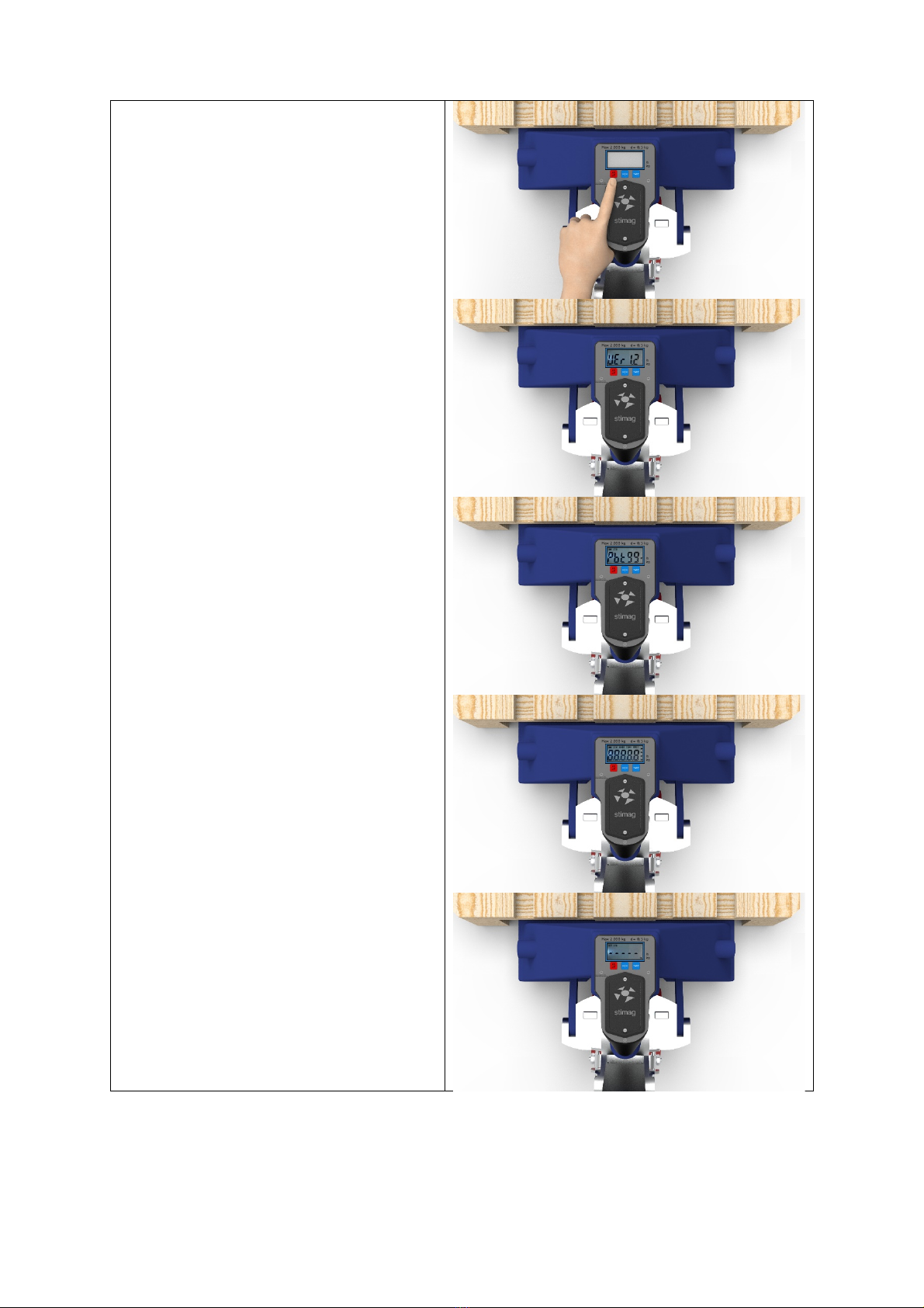
1. Turn on
Press ON/OFF It shows software version >
battery level > and then goes into self-check
end zero initialization. Then starts to normal
weighing mode.
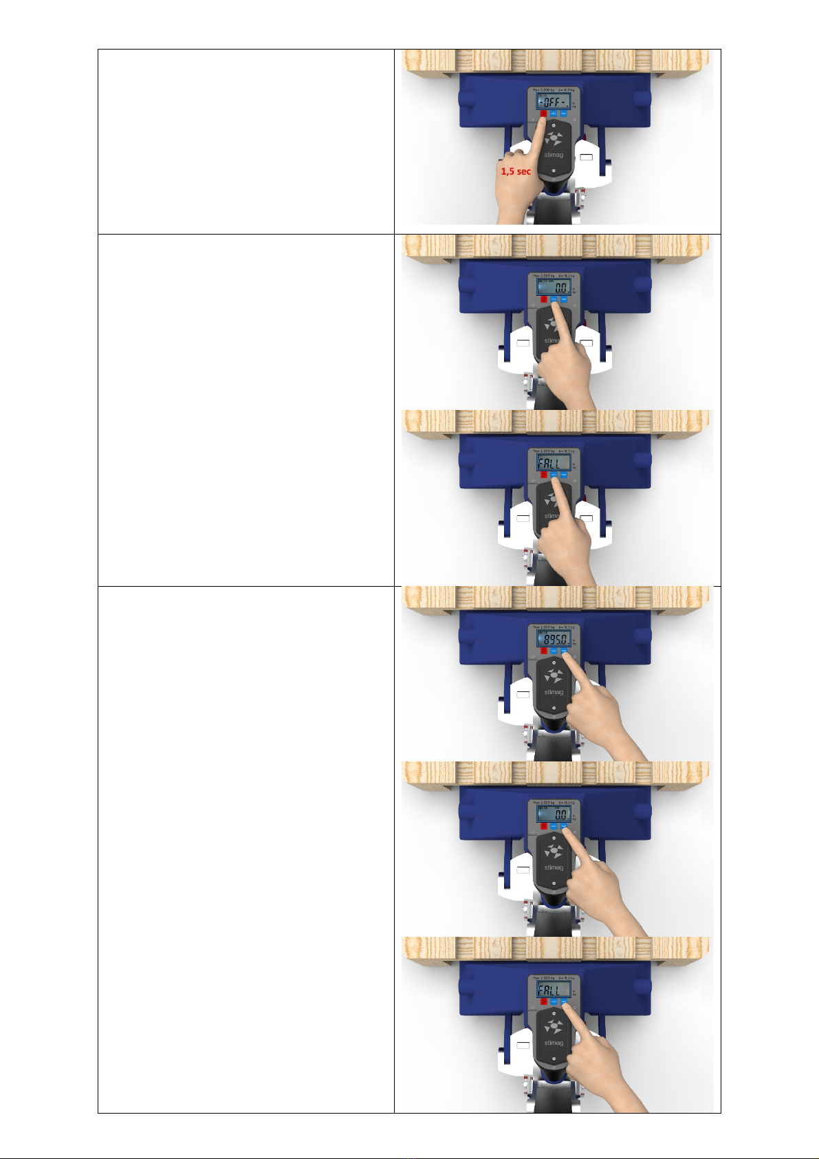
2. Turn off
Press ON/OFF for 1,5 seconds, it will show
battery level “Pbt80” (means 80% battery
level). After 2 seconds it will show “-OFF-“
and will turn off
3. Zero
Zero function is not allowed when under Tare
state. Press <0> the indicator shows FALL.
If weight is in zero range, 3% of FS and stable
press <0> to go to zero.
4. Tare
When weighing is more than zero and stable
press “Tare”, this weight is kept as tare
weight. The tare indictor on the display will
light on. The indicator will show the net
weight. When the weight is less then zero or
not stable press “Tare” the indicator shows
FALL.
Remove tare weight from the scale, press
“Tare” again to remove tare weight. The tare
indicator on the display will light off.

5. Unit switch
Press <0> and “Tare” at the same time, the
weighing unit will be switched between kg
and lb.

Setup
1. Enter setup mode
To enter setup mode press and hold <0>
followed by pressing ON/OFF. Release the
two buttons after power on. When the
indicator shows -EnC- press <0> to enter the
setup mode.
1. Divisions, select the division, change
value by pressing “Tare”. Confirm
with ON/OFF
2. Capacity, enter the preferred scale
capacity Press <0> to change digit to
the right. Press “Tare” to increase
value. (this example shows 1.500kg)
3. Confirm value by pressing the
ON/OFF button

4. Sleep/power off mode
F ABCD
A=0, sleep mode off, A=1 sleep mode on
B=0, auto-off mode off, B=1 auto-off mode
on
C= not in use
D= not in use
Change value. Press <0> to change digit to
the right. Press “Tare” to increase
Confirm with ON/OFF
Indicator will return in normal weighing
mode.

Battery
Battery
Use 3x AA size battery.
Open the battery compartment by
unscrewing the two screws as indicated.
Install the battery’s with the polarity as show
in the battery compartment.

The backlight will work automatically when the weight is changing. It will go off when the weight is
stable for 8 seconds.
If the weight is stable for 3 minutes the scale will go into sleep mode to save power. Once the weight
is changed or the scale has any operation it starts to work normally
Note: Sleep mode is only working when the scale is in zero range.
The scale will turn off automatically after 20 minutes off sleep mode. (only is automatically turn off
function is set up.)

1
A
2345678
1 2 345678
B
C
D
E
F
A
B
C
D
E
F
Dept. Technical reference Created by Approved by
Document type Document status
Title DWG No.
Rev. Date of issue Sheet
17-6-2020
1/1
STL-H SW
Rik Langeveld
- 4,5 VDC
+ 4,5 VDC
2x M8 x 16 - 00878 16
Wartel M12
Plexiglas STL-H SW
toetsenfolie STL-H SW
3D print onder
3D print boven
3x M3 - 031793
2x 2,5 x 6 - 422125 6
2x 2,5 x 6 422125 6
3x M3 x 25 - 00483 25
58319005
Batterijhouder 3x AA
BE-3MN-IP-9005
Power cable: JST-XH 2.54mm + 20cm cable, red = +, black = -
Load cell cable: Kabel LiYCY 4x0,34mm2 40 cm
E+ = brown, E- = yellow, S+ = green, S- = white
3D print Bat fixatie
3x 3D print knop

Hand Pallet Truck
INSTRUCTION MANUAL
(AC Series)
WARNING
THE MANUFACTURER SHALL NOT BE HELD LIABLE IN CASE OF
FAULTS OR ACCIDENTS DUE TO NEGLIGENCE, INCAPACITY,
INSTALLATION BY UNQUALIFIED TECHNICIANS AND IMPROPER
USE OF THE MACHINE
DO NOT OPERATE THIS MACHINE UNTIL YOU READ AND
UNDERSTAND ALL THE DANGERS,WARNINGS AND CAUTIONS
IN THIS MANUAL

Contents
Chapter 1
Introduction 1
Chapter 2
General Specifications 1
Chapter 3
To Attach Draw-bar To Pump Unit 1
Chapter 4
To Adjust Release Device 3
Chapter 5
Maintenance 3
Chapter 6
Guide To Safety Operation 4
Chapter 7
Troubles Shooting
5
Chapter 8
Spare Parts List 7

Page 1 of 13
Chapter 1 Introduction
Thank you for using our pallet truck. Your pallet truck is made of high quality steel and is
designed for the horizontal lifting and transport of loads on a pallet or standardized
containers on a level, fixed base. For your safety and correct operation, please carefully
read this instruction before using it.
NOTE: All of the information reported herein is based on data available at the moment of
printing. We reserve the right to modify our own products at any moment without notice
and incurring in any sanction. So, it is suggested to always verify possible updates.
Chapter 2 General Specifications
Capacity (kg) 2000 2500 3000
Max. Fork Height (mm) 200(or190)
Min. Fork Height (mm) 85(or75)
Fork Length (mm) 1100 / 1150 / 1220
Width Overall Forks (mm) 450 / 520 / 540 / 685
Individual Fork Width (mm) 160
Load WheelDiameter (mm) Ø 82x70(or Ø 74x70)Nylon, Polyurethane
Steering Wheel Diameter (mm) Ø 200(or Ø 180)Nylon, Polyurethane, Rubber
Special fork length are available 800, 900, 950, 1000, 1500, 2000mm.
Materials and specification are subject to change without notice.
Chapter 3 To Attach Draw-bar To Pump Unit
If you have purchased a wooden box of pallet truck, some assembly is required.
Certainly, you need some tools, a hammer, a pliers, a spanner, etc; and some parts, one
axle with hole (A105), two elastic pins (A106)(Note one is in the axle (A105)), these
parts are putted in a plastic bag, which is putted into the draw-bar.
Page 2 of 13
NOTE: The number of draw-bar and pump should be the same.
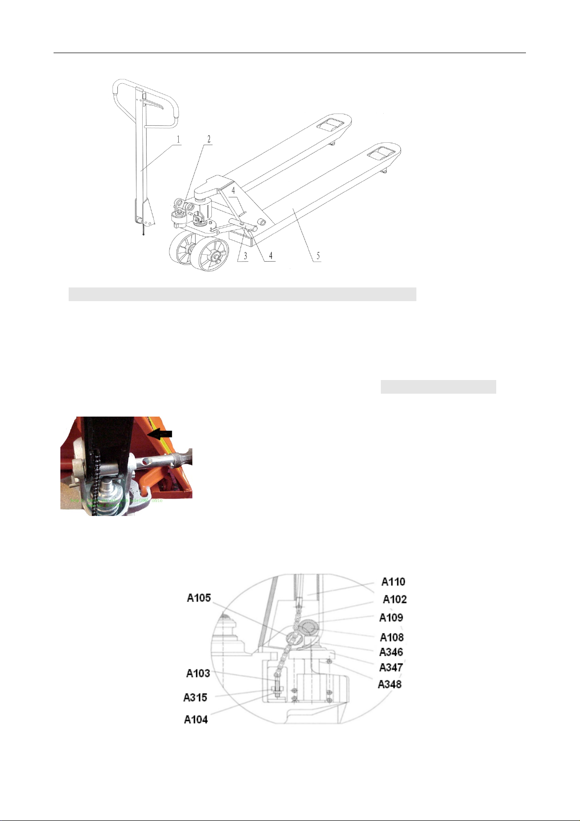
1. Draw-bar 2. Pin 3. Axle with hole 4. Elastic pin 5. Fork frame
Fig. 1
When attaching the handle, you had better squat just behind the pallet truck. Then you:
3.1 Insert the draw-bar onto the pump piston (A346), then use a hammer to insert the
axle with hole (A105) into the hydraulic pump and draw-bar from the right to left. (See
fig. 2 ).
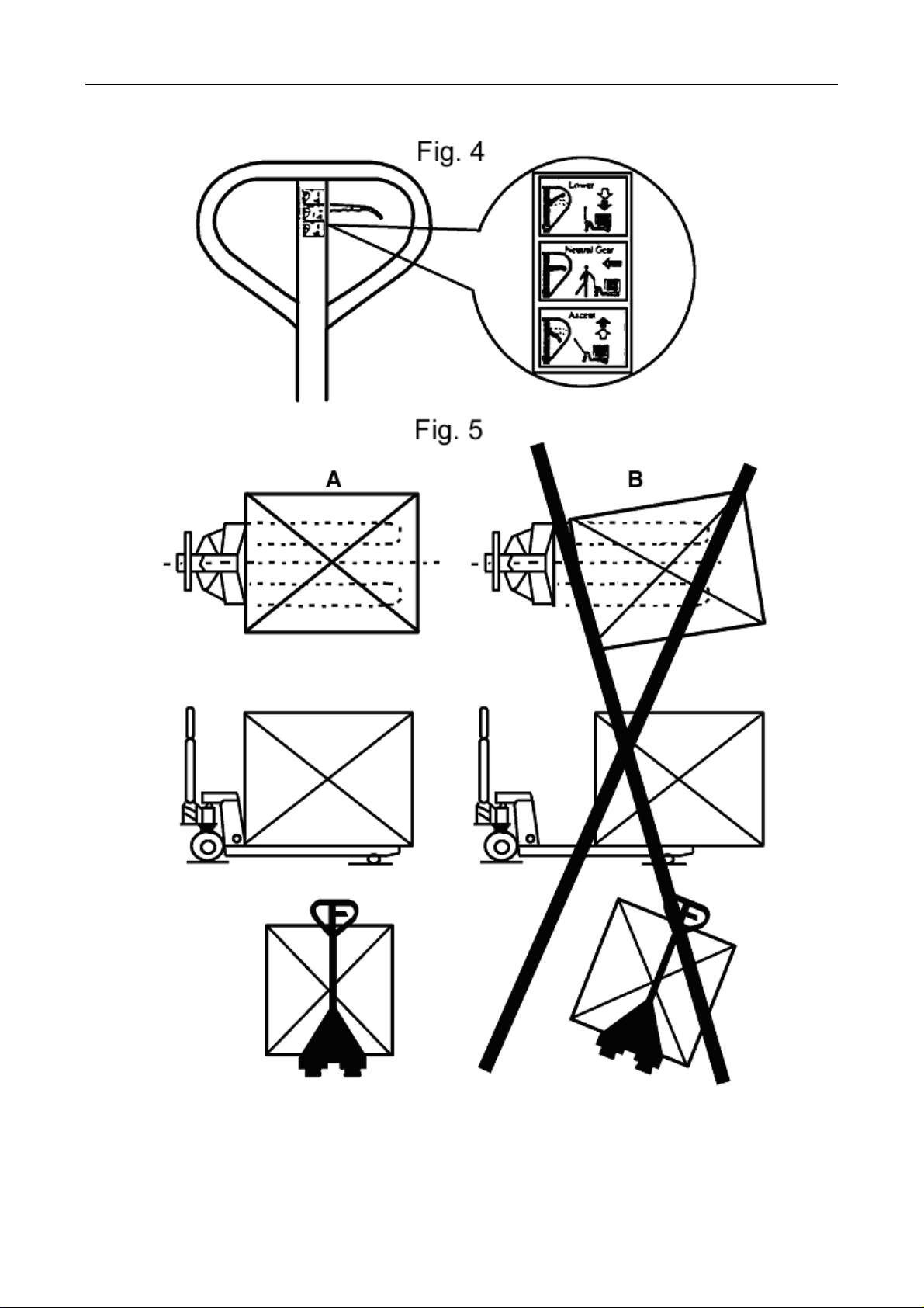
3.2 Let control handle(A117) to the ‘LOWER’ position, then
pass the adjusting nut(A104), adjusting bolt(A103) and
chain(A102) through the hole of axle(A105) with your hand
(See fig. 3).
Fig. 2
Fig. 3

Page 3 of 13
3.3 Press the draw-bar (A110, A110B) down, take away the pin(#2) (See Fig. 1).
3.4 Let the control handle (A117) on ‘RAISE’ position, then raise the lever plate (A315)
with the pin (#2) and insert the adjusting bolt(A103) into the front slot of lever plate
(A315), note to keep the adjusting nut (A104) on the under side of the lever plate.
3.5 Use a hammer to tap another elastic pin (A106) into the axle with hole (A105).
The draw-bar is now assembled to the pump.
Chapter 4 To Adjust Release Device
On the draw-bar of this pallet truck, you can find the control handle(A117) which can be
regulated in three positions :
Raise -handle down
Drive position -handle in center position
Lower -handle up, the lever moves backthe drive position when released.
If however they have been changed, you can adjust according to following step:
4.1 If the forks elevate while pumping in the DRIVE position, turn the adjusting nut (A104)
on the adjusting bolt(A103) or screw(A318) clockwise until pumping action does not raise
the forks and the DRIVE position functions properly.
4.2 If the forks descend while pumping in the DRIVE position, turn the nut(A104) or
screw(A318) counter-clockwise until the forks do not lower.
4.3 If the forks do not descent when the control handle (A117) is in the LOWER position,
turn the nut(A104) or screw (A318) clockwise until raising the control handle(117) lowers
the forks. Then check the DRIVE position according to item 3.1 and 3.2 to be sure the
nut (A104) and screw(A318) is in the proper position.
4.4 If the forks do not elevate while pumping in the RAISE position, turn the nut (A104) or
screw (A318) counter-clockwise until the forks elevate while pumping in the RAISE
position. Then check the LOWER and DRIVE position according to item 3.1, 3.2 and
item 3.3.
Chapter 5 Maintenance
The pallet truck is largely maintenance-free.
5.1 OIL
Please check the oil level every six months. The oil can be hydraulic oil: ISO VG32, its
viscosity should be 30cSt at 400C, total volume is about 0.4lt.
5.2 TO BANISH THE AIR
The air may come into the hydraulic oil because of transportation or pump in upset
position. It can cause that the forks do not elevate while pumping in the RAISE position.
The air can been removed in the following way: let the control handle (A117) on the
LOWER position, then move the draw-bar up and down for several times.
5.3 DAILY CHECK AND MAINTENANCE

Page 4 of 13
Daily check of the pallet truck can limit wear as much as possible. Special attention
should be paid to the wheels, the axles, as thread, rags, etc. It may block the wheels.
The forks should be unloaded and lowered in the lowest position when the job is over.
5.4 LUBRICATION
All bearings and shafts are provided with long-life grease at the factory. You only need
provide with long-life grease at monthly intervals or after each time the truck is cleaned
thoroughly to the lubrication points.
Chapter 6 Guide To Safety Operation
6.1 Operator should read all warning signs and instructions here and on the pallet truck
before using this truck.
6.2 Do not use on a slopping ground.
6.3 Do not operate a pallet truck unless you are familiar with it and have been trained or
authorized to do so.
6.4 Do not operate a pallet truck unless you have checked its condition. Give special
attention to the wheels or rollers, the draw-bar unit, the fork unit, the lever plate, etc. .
6.5 To pull the truck, always move the control handle into the drive position. This makes
the draw-bar easier to move and depressurizes the pump section of the hydraulics. This
preserves the hydraulic seals and the valve components. A long service life can be
expected.
6.6 Do not take up any people on the pallet truck.
6.7 The operator had better take on gloves for labor protecting.
6.8 When the goods have been transported, all people should be away from the forks for
600mm.
6.9 Do not load goods like fig. 5/B .
6.10 Do not load over maximum capacity.
6.11 At others special condition or place, the operator should be carefully to operate the
pallettruck.

Page 5 of 13
Chapter 7 Troubles Shooting
No Trouble Clause Fixing Methods
1
The forks
can not be
up the max.
height.
-The hydraulic oil is not
enough. -Pour in the oil.
2 The forks
can not be
lifted up.
-Without hydraulic oil.
-The oil has impurities.
-The nut (114) is too high,
keep the pumping valve open.
-Air come into the hydraulic oil.
-Fill in the oil.
-Change the oil.
-Adjust the nut(A104) or screw
(A318) (see item 3.4)
-Banish the air.(see item 4.2)
3 The forks
can not be
descended.
-The piston rod or pump body
is deformed resulting from
piston rod(246)or partial
loading slanting to one side or
over-loading.
-The fork was kept in the high
position for long time with
piston rod bared to arise in
rusting and jamming of the
rod.
-The adjusting nut (114)is not
in correct position.
-Replace the piston rod
(A344) or pump (A328).
-Keeping the fork in the lowest
position if not using, and pay
more attention to lubricate the
rod.
-Adjust the nut (A104) or
screw (A318) (see item 3.3)
4 Leaks
-Sealing parts worn or
damaged.
-Some part cracked or worn
into small.
-Replace with the new one.
-Replace with the new one.
5
The fork
descends
without the
release
valve
worked.
-The impurities in the oil cause
the release valve to be unable
to close tight.
-Some parts of hydraulic
system is cracked or bored.
-Air come into the oil.
-Sealing parts worn or
damaged.
-The adjusting nut (A104) or
screw (A318) is not in the
correct position.
-Replace with new oil.
-Inspect and replace the
waste parts.
-Banish the air. (See item 4.2)
-Replace with the new one.
-Adjusting the nut (A104) or
screw (A318). (See item 3.2)
NOTE: DO NOT ATTEMP TO REPAIR THE PALLET TRUCK UNLESS YOU ARE
TRAINED AND AUTHORIZED TO DO SO.
Page 6 of 13
Page 7 of 13
Chapter 8 Spare Parts List

Page 8 of 13
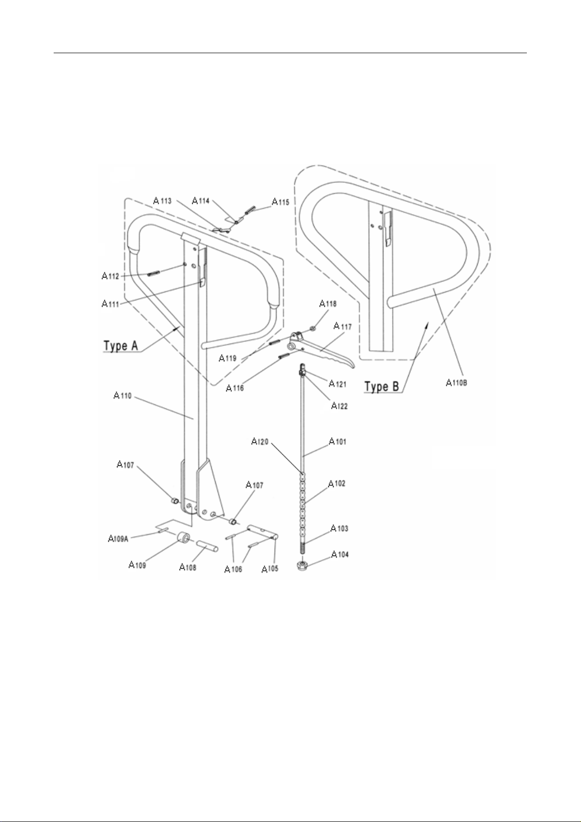
LIST of DRAW-BAR
No. Description Qty. Remark
A101 Release Rod 1
A102 Chain 1
A103 Adjusting Bolt 1
A104 Adjusting Nut 1
A105 Axle with Hole 1
A106 Elastic Pin 2
A107 Bushing 2
A108 Roller Pin 1
A109 Pressure Roller 1
A109A Elastic Pin 1
A110 Draw-bar 1 For Type A
A110B Draw-bar 1 For Type B
A111 Stop Rubber 1
A112 Elastic Pin 1
A113 Blade Spring 1
A114 Spring 1
A115 Elastic Pin 1
A116 Elastic Pin 1
A117 Control Handle 1
A118 Roller 1
A119 Elastic Pin 1
A120 Pin 1
A121 Pull Board 1
A122 Pin 1

Page 9 of 13
LIST OF FORK FRAME
No. Description Qty. No. Description Qty.
A201 Fork Frame 1 A216 Shaft 2
A202 Bolt 1 A217* Elastic Pin 4
A203 Rock-Arm 1 A218* Linking Plate 4
A204 Shaft 2 A219 Shaft for Roller 1or4
A205 Pin 1 A221 Washer 8or4
A206 Retaining Ring 2 A222 Bearing 8or4
A207 Adjust Seat 2 A223* Loading Roller 4
A208 Pin 2 A224 Bolt 2
A209 Shaft 1 A225 Enter Roller 2
A210 Pushing Rod 2 A226 Nut 8or2
A211 Shaft 2 A227 Elastic Pin 2
A212 Elastic Pin 2 A228# Shaft for Roller 2
A213 Frame of Roller 2 A229# Loading Roller 2
A215 Retaining Ring 2
NOTE: *-- For double wheel;#-- For single wheel
Table of contents
Popular Truck manuals by other brands

freightliner
freightliner Custom Classic MT45 2022 Maintenance manual

HELI
HELI CBD15J-Li2 Series manual

Motrec
Motrec E-290GT Operator and maintenance manual

Labrie
Labrie ALLEY-GATOR RIGHT-HAND Operator's manual

Mercedes-Benz
Mercedes-Benz Unimog 435 Service manual

Komatsu
Komatsu HD465-8 Operation & maintenance manual


