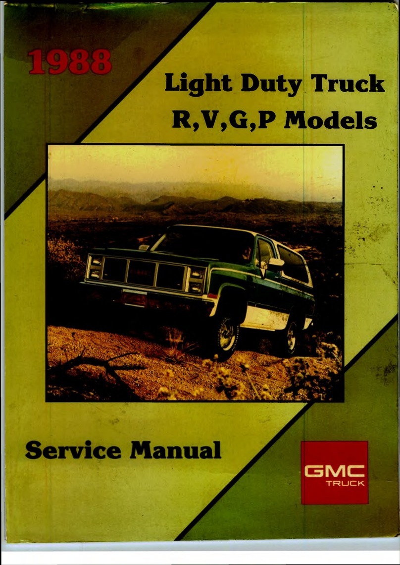
GMC 1982 Light Duty Truck User manual


FOREW ORD
This manuai includes procedures for diagnosis, maintenance and
adjustments, minor service operations, removal disassembly and
installation for components of GMC Truck & Coach ivision Series
1500-3500 Light uty Trucks. Procedures for “S-15” and Caballero are
contained in separate service manuals.
The Section Index on the contents page enables the user to quickly
locate any desired section. At the beginning of each section
containing more than one major subject is a Table of Contents, which
gives the page number on which each major subject begins. An index
is placed at the beginning of each major subject within the section.
Summaries of Special Tools, when required, and specifications are
found at the end of major sections.
When reference is made in this manual to a brand name, number, or
specific tool an equivalent product may be used in place of the
recommended item.
This manual should be kept in a handy place for ready reference. If
properly used, it will enable the technician to better serve the owners
of GMC Truck & Coach ivision built vehicles.
Ail information, illustrations and specifications contained in this
literature are based on the latest product information available at the
time of publication approval. The right is reserved to make changes at
any time without notice.
GM C TRUCK & COACH
Division of General Motors Corporation
Pontia , Mi higan 48053

IMPORTANT SAFETY NOTICE
Proper service and repair is important to the safe, reliable operation of all
motor vehicles. The service procedures recommended and described in this
service manual are effective methods for performing service operations.
Some of these service operations require the use of tools specially designed
for the purpose. The special tools should be used when and as recommended.
It is important to note that this manual contains various autions and
Notices which should be carefully read in order to minimize the risk of
personal injury to service personnel or the possibility that improper service
methods will be followed which may damage the vehicle or render it unsafe.
It also is important to understand that these autions and Notices are not
exhaustive. The manufacturer could not possibly know, evaluate and advise
the service trade of all conceivable ways in which service might be done
or of the possible hazardous consequences of each way. onsequently,
the manufacturer has not undertaken any such broad evaluation. Accord
ingly, anyone who uses a service procedure or tool which is not recommend
ed must first satisfy himself thoroughly that neither his safety nor vehicle
safety will be jeopardized by the service method he selects.

1982
LIGHT DUTY
TRUCK
(Series 10-35)
SHOP ANUAL
TABLE OF CONTENTS SECTION
GENERAL INFORMATION
General Inform ation OA
Maintenan e and Lubri ation OB
HEATING AND AIR CONDITIONING
Heating and Ventilation 1A
Air Conditioning IB
R-4 Compressor 1C1
A-6 Com pressor 1D
FRAME AND BUMPERS
Frame and Body M ounts 2A
Bum pers 2B
Sheet M etal 2C
Body 2D
STEERING, SUSPENSION, WHEELS
AND TIRES
Front A lignm ent 3A
Steering Linkage 3B1
M anual Steering 3B2
Power Steering 3B3
Steering Column 3B4
Front Suspension 3C
Rear Suspension 3D
W heel and Tires 3E
PROPELLER SHAFT AND REAR AXLE
Propeller Shaft 4A
Rear Axles 4B
Front W heel Drive 4C
BRAKES 5
ENGINE
Engine 6
In-Line 6 6A1
Sm all Blo k 6A4
Mark IV 6A5
6.2L Diesel 6A7
Engine Cooling 6B
Engine Fuel 6C
M odel 1ME 6C1
Model 2SE 6C2
Model M 4M C/M 4M E 6C4
Fuel System - Gasoline 6C5
Diesel Fuel Inje tion 6C6
Engine Ele tri al 6D
Engine Emission Controls 6E
Engine Exhaust 6F
TRANSMISSION
Autom ati 7A
Manual 7B
Clut h 7C
Transfer Case 7E
ELECTRICAL — BODY AND CHASSIS
Lamps and Lighting 8A
Ele tri al and Wiring 8B
Instrument Panel Gages and 8C
Wiring Diagrams
ACCESSORIES 9
METRIC AND FASTENER INFORMATION 10
CAUTION
These vehicles contain some parts dimensioned in the metric
system as well as in the customary system. Some fasteners are
metric and are very close in dimension to familiar customary
fasteners in the inch system. It is important to note that, during
any vehicle maintenance procedures, replacement fasteners must
have the same measurements and strength as those removed,
whether metric or customary. (Numbers on the heads of metric
bolts and on surfaces of metric nuts indicate their strength.
ustomary bolts use radial lines for this purpose, while most
customary nuts do not have strength markings.) 'Mismatched or
incorrect fasteners can result in vehicle damage or malfunction, or
possibly personal injury. Therefore, fasteners removed from the
vehicle should be saved for re-use in the same locations whenever
possible. Where the fasteners are not satisfactory for re-use, care
should be taken to select a replacement that matches the original.
For information and assistance, see your dealer.
© 1981 General Motors Corporation Printed in U.S.A.

GENERAL INFORMATION OA-1
SECTION OA
GENERAL INFOR ATION
CONTENTS OF THIS SECTION
General..
...............................
.
.................................................................................
.
0-1
Vehicle Identification Number
................
.........................................................
.
0-2
Service Parts Identification Stic er
...................................................................0-3
Vehicle Loading
................
,....................................................................................0-3
Engine Code Number..........................................................................................
.
0-3
Unit and Serial Number Locations..................................................................
.
0-3
GENERAL
Information to identify the vehicle and vehicle compo
nents appears in this section. Detailed specifications on
major units are given at the end of each respective section in
this manual.
VEHICLE IDENTIFICATION NUMBER (VIN)
This is the legal identification of the vehicle. It appears
on a plate which is attached to the left top of the instrument
panel on CK and G truc and can be easily seen through the
windshield from outside the vehicle (Fig. 0A-1). On P10-20-
30 models, the plate is attached to the front of the dash and
toe panel to the left of steering column (Fig. 0A-2). The
VIN also appears on the Vehicle Certificates of Title and
Registration.
o[ 1GCEC14D9BF123456] o
TYPIC AL VIN
100818
Fig. 0A-1--Vehicle Identification Number Location ( K
and G)
r MFD. BY GENERAL MOTORS CORPORATION ^
O GVWRf ^ ^ l U
GAWR FR ONT^ ^ ^ GAWR REAR
vi»
o
INFLATION DATA FOR TIRES FURNISHED WITH VEHICLE
SHOWN ON VEHICLE CERTIFICATION LABEL
WARRANTY VOIDED IF LOADED IN EXCESS OF RATINGS
SEE OWNERS MANUAL FOR OTHER LOADING AND INFLATION DATA
EXAMPLE ONLY
Fig. 0A-2--V.I.N. Rating Plate (P Model)

OA-2 GENERAL INFORMATION
VEHICLE IDENTIFICATION NUMBER
GCEC14D9CF123456
N A T IO N O F O R IG IN
1 U S A
2 ANADA
M A N U F A C TU R E R
3 GENERAL MOTORS
M A K E A N D TYP E
BUS IVAN)
IN OMPLETE VEHI LE
TRU K
MULTIPURPOSE PASS. VEHI LE
G V W R /B R A K E SYSTEM
GVWR
CO E (IN POUN S) BRAKE SYSTEM
B 3001 - 4000
‘ 4001 - 5000
D 5001 - 6000
E 6001 - 7000 HYDRAULI ONLY
F 7001 - 8000
"C , 8001 9000
H 9001 10000
J 10001 1 1.000
Includes El amino
Includes G Van Bus.
TR UC K SERIE S
1 1/2 TON
2 3/4 TON
3 1 TON
8 112 TON
(EL AMINO)
LIN E A N D CHA SS IS T YPE
LINE MO ELS
ONVENTIONAL AB ( l
ONVENTIONAL AB (K)
FORWARD ONTROL HASSIS (P|
VAN. SPORT VAN & UTAWAY VAN (G)
E L AMINO (APU)
CHASSIS
TYPE
4X2
4X4
4X2
4X2
4X2
J
M O D EL Y EA R
C 1982
1983
E 1984
F1985
G1986
H1987
1988
1989
1090
M1991
H P LA N T SE U E N T IA L N U M B E R ]
ASS EM BLY P LA N T
CO E ASSEMBLY PLANT CO E ASSEMBLY PLANT
AGMAD LAKEWOOD SGMAD ST LOUIS
BGMAD BALTIMORE VGMT & PONTIA
DGMAD - DORAVILLE * zGMAD FREMONT *
FHEVROLET FLINT 1 GM OF ANADA OSHAWA
JGMAD - JANESVILLE 3HEVROLET DETROIT
KGMAD - LEEDS * 4GM OF ANADA S ARBOROUGH
RGMAD ARLINGTON ' 7GMAD LORDSTOWN
' EL AMINO PLANTS
CH EC K D IG IT
TR U CK BO D Y TYPE
0 SEDAN PI KUP
1 HI UBE/ UTAWAY VAN
2 FORWARD ONTROL
3 FOUR DOOR AB
4 TWO DOOR AB
5 VAN
6 Su b u r b a n
7 MOTOR HOME
8 BLAZER
9 STAKE/PLATFORM
EN GIN E TYPE A N D M A KE
TYPE MAKE (GM)
CO E ISPLACEMENT LITRES PRO UCER MO ELS RPO
C6 .2 L V 8 IE S E L HEVROLET C-K LN 6
D4 1 L L6 2BBL HEVROLET GLE3
F5.0L V8 4BBL HEVROLET K G LF3
H5 0L V8 4BBL HEVROLET K G LE9
J6 .2 L V 8 IE SE L C H E VR O L ET C-K L L 4
L5 7L V8 4BBL HEVROLET K G LS9
M5.7L V8 4BBL HEVROLET K G P LT9
P5.7L V8 2BBL HEVROLET -K LF5
W7 4L V8 4BBL HEVROLET -K P LE8
T4 8L L6 1 BBL HEVROLET K P L25
(FOR EL CAMINO O NLY)
V I.N . TYPE M AKE (GM)
CO E ISPLACEMENT LITRES PRO UCER MO EL RPO
A3.8L V6 2BBL BUICK EL CAMINO LD5
H5.0L V8 4BBL CHEVROLET EL CAMINO LG4
J4 4L V8 2BBL CHEVROLET EL CAMINO L39
K3.8L V6 2BBL CHEVROLET EL CAMINO LC3
Fig. 0A-3--Vehicle Identification Number

GENERAL INFORMATION OA-3
SERVICE PARTS IDENTIFICATION STICKER
The Service Parts Identification Stic er (Fig. OA-6) is
provided on all Truc models. On C and K models, the
identification stic er be located on the inside of the glove box
door or on G model, the stic er will be located on an inner
hood panel surface. On P models, the stic er is located on a
inner body panel.
The plate lists the vehicle identification number,
wheelbase, and all Production options or Special Equipment
on the vehicle when it was shipped from the factory
including paint information. ALWAYS REFER TO THIS
INFORMATION WHEN ORDERING PARTS.
VEHICLE LOADING
Vehicle loading must be controlled so weights do not
exceed the numbers shown on the Vehicle Identification
Number and/or Rating Plate for the vehicle.
A typical example of a truc in a loaded condition is
shown in Figure OA-7. Note that the axle or GVW capabili
ties are not exceeded.
ENGINE CODE NUMBER
The engine code number indicates producing
plant, month and day of manufacture, and transmission
type. A typical engine number would be F1210TTBB, which
would brea down thus:
F - Producing Plant (F-Flint, T-Tonawanda)
12 - Month of Manufacture (December)
10 - Day of Manufacture (tenth)
T - Truc
TBB - Transmission and engine type
UNIT AND SERIAL NUMBER LOCATIONS
For the convenience of service technicians and engi
neers when writing up certain business papers such as
Warranty Reports, Product Information Reports, or report
ing product failures in any way, the location of the various
unit numbers have been indicated. These unit numbers and
their prefix or suffix are necessary on these papers for
various reasons - such as accounting, follow-up on produc
tion, etc.
The prefixes on certain units identify the plant in which
the unit was manufactured and thereby permits proper
follow-up of the plant involved to get corrections made when
necessary.
Always include the prefix in the number.
SERVICE PARTS IDENTIFICATION
V.I.N | ■ mu-- H i
V 1 N - VlMlCli IDENTIFICATION NUMBER
NOTE I THE SPECIAL EQUIPMENT LIS
PARTS BE SURE TO SPECIF'
TED BELOW MAS BEEN INSTALLED ON
IDENTIFIC A TION OF REPLACEMENT
THE APPLICABLE OPTION NUMBERS
DE SCR IPTIO N OPTION D E SCR IPTIO N
■■
Axles
Chevrolet Built
• On 10 Series, the Code is stamped on Top of Right
Rear Axle Tube.
• On 20-30 Series, the Code is stamped on Top of the
Right Rear Axle Tube.
Dana Built
• On Front Axles, code is stamped on Top Rear of Left
Axle Tube.
• On Rear Axles, code is stamped on Rear Surface of
Right Axle Tube.
Transmissions (Fig. OA-6)
• On 3-Speed Transmissions (except Tremec), the Unit
Number is located on Lower Left Side of Case Just
Below Cover.
• On Tremec Transmissions, Unit Number is located on
Upper Left Attachment Case (Top Side).
• On Muncie 4-Speeds, Unit Number is located on Rear
Face of Case below Retainer.
• On New Process 205 model 4-wheel drive transfer case,
a build date is on tag attached to front face of transfer
case.
• On Automatic 350 Transmission, Unit Number is
Located on Right Rear Vertical Surface of Oil Pan.
• On the Automatic 400 Transmission, Serial Number is
Located on the Light Blue Plate on the Right Side of
the Transmission.
• On the Automatic 700R4 Transmission, the
Unit Number is stamped on the cover pan rail
on the Right Side of the Transmission.
I PORTANT: RETAIN THIS PLATE AS A PER ANENT RECORD
L O A D E D -M A X IM U M G VW R: 4900-LBS.
FRONT GAWR: 2944 LBS. REAR GAWR: 2944 IBS.
Front urb
Front argo &
Pass. Load
2219 lbs.
284 lbs.
*Rear urb
Rear argo &
Pass. Load
2503 lbs.
1003 lbs.
1394 lbs.
2397 lbs.
TOTAL WEIGHT AT GROUND: 4900 lbs.
* urb weight equals the weight of the vehicle without driver,
passenger or cargo, but including fuel and coolant.
Fig. 0A-4-Service Parts Identification Plate Fig. 0A-5--Typical Vehicle Loading ondition

OA-4 GENERAL INFORMATION
TYPICAL TRANSMISSION - I D LOCATIONS
H THM 350C STAMPED I D LOCATION
I THM 350C VIN LOCATION
J. THM 350C OPTIONAL VIN LOCATIONS
K. THM 400 I D TAG LOCATION
I THM 400 VIN LOCATION
M. THM 700 R4 STAMPED I D LOCATION
N. THM 700 R4 VIN LOCATION H 7 A 1 6/81
TRANSMISSION IDENTIFICATIO N
FOR: THM 35 0C -T OL ED O PLANT, OHIO
Y 2 E 03 D
Y = SOURCE (Y = TOLEDO B = PARMA)
2 = MODEL YEAR
E = MONTH (A = JAN B = FEB)
03 = DAY
D = SHIFT <D = DAY SHIFT N = NIGHT SHIFT)
H 7A-8-6/81
TRANSMISSION NAMEPLATE
YPSILANTI PLANT, MICHIGAN
P • z
82-PZ 86992
82 = MODEL YEAR
PZ = MODEL
86992 = SERIAL NO.
H 7 A-12-6/81
TRANSMISSION NAMEPLATE
BUICK FLINT PLANT, M ICHIGAN
THM 350C
9LD = MODEL CODE (1982 LD)
001 = PRODUCTION BUILD DATE
D = SHIFT (D = DAY SHIFT)
82 = YEAR
H 7 A-9-6/81
TRANSMISSION ID ENTIFICA TIO N
THM 700R4 -TO L ED O PLANT, OHIO
9 TA Y 2 M 12 D
9 = MODEL YEAR
TA = MODEL
Y = TOLEDO
2 = YEAR
M = MONTH
12 = DAY
D = SHIFT (D = DAY N = NIGHT)
H 7A-7-6/81
102867
Fig. 0A-6--Transmission V.I.N. Location

GENERAL INFORMATION OA-5
V8 EN GIN E-D IESEL 1Q0820
DISTRIBUTOR PAD
L6 ENGINE
ENGINE V.I.N. #
(OPTIONAL) ENGINE
V.I.N.
ENGINE V.I.N.
(OPTIONAL) ENGINE
ASE PAD
V8 ENGINE
Fig. 0A-7--Engine V.I.N. Location
Engines (Fig. OA-7)
• 6-Cylinder Engine Unit Number Located on Pad at
Right Hand Side of Cylinder Bloc at Rear of
Distributor.
• 8-Cylinder Gasoline Engine Code is (305, 350, 400
CID) Located on Pad immediately forward of right
hand cylinder head.
• 8-Cylinder Gasoline Engine (454 CID) Code is located
on a pad of the front top center of the engine bloc
immediately forward of the inlet manifold.
• 8-Cylinder Diesel Engine Code is on a label located on
rear face of the left valve cover.
Generators
Generator Unit Serial Number is located on the Drive
End Frame Below the Part Number.
Batteries
Battery Code Number is Located on Cell Cover Top of
Battery.
Starters
Starter Serial Number and Production Date are
Stamped on Outer Case, Toward Rear.

MAINTENANCE AN LUBRICATION OB-1
SECTION OB
AINTENANCE AND LUBRICATION
CONTENTS
Maintenance Schedule..................................................................................... OB-6
General Maintenance
..................................................................................... OB-6
Emission Control Maintenance.................................................................. OB-11
Recommended Fluids and Lubricants........................................................ OB-13
Fluid Capacities................................................................................................ OB-14

OB-2 MAINTENANCE AN LUBRICATION
1982 VEHICLE MAINTENANCE SCHEDULE
Item
No. To Be Servi ed When to Perform
7,500 Miles
(12 000 km)
15,000 Miles
(24 000 km)
22,500 Miles
(36 000 km)
30.000 Miles
(48 000 km)
37,500 Miles
(60 000 km)
45,000 Miles
(72 000 km)
SECTION A - GENERAL MAINTENANCE
A-1 Chassis Lubrication Lubricate every 12 Months or 7,500 Miles (12 000 km) • • • • ••
A-2 Fluid Levels Check every 12 Months or 7,500 Miles (12 000 km) • • • • • •
A-3 Engine Oil and Filter* See Explanation for service intervals
A-4 Clutch Inspect every 12 Months or 7,500 Miles (12 000 km) • • • • • •
A-5 Steering and Suspension • • • • ••
A-6 Exhaust System* Inspect every 12 Months or 7,500 Miles (12 000 km) • • • • • •
A-7 Tires and Wheels Inspect and rotate at 7,500 Miles (12 000 km), then every
15,000 Miles (24 000 km) • • •
A-8 Brakes
Disc Brakes Inspect at 7.500 Miles (12 000 km), then every 15,000 Miles
(24 000 km) •• •
Brake Lines Inspect every 12 Months or 7,500 Miles (12 000 km) ••• • • •
Drum and Parking Brakes Inspect every 12 Months or 15,000 Miles (24 000 km) • • •
A-9 Engine Drive Belts* Inspect every 12 Months or 15,000 Miles (24 000 km) •••
A-10 Fuel Tank, Cap, and Lines* • • •
A-11 Throttle Linkage • • •
A-12 Cooling System* Service per Explanation every 12 Months or 15,000 Miles
(24 000 km) • • •
Drain, flush and refill every 24 Months or 30,000 Miles
(48 000 km) •
A-13 Manual Steering Gear Inspect every 30,000 Miles (48 000 km) •
A-14 Final Drive See Explanation for service intervals
A-15 Wheel Bearings Repack every 30,000 Miles (48 000 km) •
A-16 Transmission Fluid See Explanation for service intervals
SECTION B - EMISSION CONTROL MAINTENANCE
B-1 Carburetor Choke and Hoses Check at 6 Months or 7,500 Miles (12 000 km), then at 24
Month or 30,000 Mile (48 000 km) intervals. Also check B-1
and B-4 at 45,000 Miles (72 000 km).
••0
B-2 Carburetor or Throttle Body Mounting 2 • •
B-3 Engine Idle Speed (See Explanation) ••
B-4 Vacuum Advance System •••
B-5 Thermostatically Controlled Air Cleaner Inspect at 7,500 Miles (12 000 km), then every 30,000 Miles
(48 000 km) ••
B-6 Spark Plug Wires and Distributor Inspect every 15,000 Miles (24 000 km) • • •
B-7 Spark Plugs Replace every 30,000 Miles (48 000 km) •
B-8 PCV System Check and Service See Explanation for service intervals
B-9 Engine Timing Adjust every 30,000 Miles (48 000 km) •
B-10 EGR System Service every 36 Months or 30,000 Miles (48 000 km) •
B-11 Air Cleaner and PCV Filter See Explanation for service intervals
B-12 EFE System3 Check at 7,500 Miles (12 000 km), then at 30,000 Miles
(48 000 km) • •
B-13 ECS Check at 30,000 miles (48 000 km) •
B-14 Idle Stop Solenoid •
B-15 Fuel Filter Service every 15,000 Miles (24 000 km) •• •
B-16 Valve Lash Adjustment1 • • •
•Also an Emission Control Service
Altitude Adjustment: Your 1982 General Motors vehicle has been certified to meet emission standards at high
and'or low altitude. Certain vehicles sold for high altitude use have been adjusted prior to delivery for improved
driveability and emission control at high altitude. These vehicles may be identified by an additional underhood
tune-up label, "Supplemental Vehicle Emission Control Information.” Information regarding adjustment of your
vehicle, if permitted, can be obtained from the Consumer Relations Office shown in the Owner Assistance
Section of your Owners and Driver s Manual In lude your Vehi le Identifi ation Number in your request.
1 Only applicable to 1.9L engine, Engine Family C1G1.9T2HEC7.
2 All engines EXCEPT 1.9L, Engine Family C1G19T2HEC7
3 Not applicable to 1 9L and 2 81 engines.
Fig. OB-1--Maintenance Schedule, Gasoline, Light Duty Emissions, 49 States

MAINTENANCE AN LUBRICATION OB-3
1982 VEHICLE MAINTENANCE SCHEDULE
Item
No. To Be Servi ed When to Perform
7,500 Miles
(12 000 km)
15,000 Miles
(24 000 km)
22,500 Miles
(36 000 km)
30,000 Miles
(46 000 km)
37,500 Miles
(60 000 km)
45,000 Miles
(72 000 km)
SECTION A - GENERAL MAINTENANCE
A-1 Chassis Lubrication Lubricate every 12 Months or 7,500 Miles (12 000 km) •• • •••
A-2 Fluid Levels Check every 12 Months or 7,500 Miles (12 000 km) • • • • • •
A-3 Engine Oil and Filter* See Explanation for service intervals
A-4 Clutch Inspect every 12 Months or 7,500 Miles (12 000 km) •• • • ••
A-5 Steering and Suspension •• • •••
A-6 Exhaust System* Inspect every 12 Months or 7,500 Miles (12 000 km) • • • • • •
A-7 Tires and Wheels Inspect and rotate at 7,500 Miles (12 000 km), then every
15,000 Miles (24 000 km) •« •
A-8 Brakes
Disc Brakes Inspect at 7,500 Miles (12 000 km), then every 15,000 Miles
(24 000 km) •••
Brake Lines Inspect every 12 Months or 7,500 Miles (12 000 km) • • • • • •
Drum and Parking Brakes Inspect every 12 Months or 15,000 Miles (24 000 km) •••
A-9 Engine Drive Belts* Inspect every 12 Months or 15,000 Miles (24 000 km)
• 1•• 1
A-10 Fuel Tank, Cap, and Lines* •••
A-11 Throttle Linkage •••
A-12 Cooling System* Service per Explanation every 12 Months or 15,000 Miles
(24 000 km) •••
Drain, flush and refill every 24 Months or 30,000 Miles
(48 000 km) •
A-13 Manual Steering Gear Inspect every 30,000 Miles (48 000 km) •
A-14 Final Drive See Explanation for service intervals
A-15 Wheel Bearings Repack every 30,000 Miles (48 000 km) •
A-16 Transmission Fluid See Explanation for service intervals
SECTION B - EMISSION CONTROL MAINTENANCE
B-1 Carburetor Choke and Hoses Check at 6 Months or 7,500 Miles (12 000 km), then at 24
Month or 30,000 Mile (48 000 km) intervals. Also check B-1
at 45,000 Miles (72 000 km).
•Q 2•
B-2 Carburetor or Throttle Body Mounting4 • 2•
B-3 Engine Idle Speed (See Explanation) • 2 •
B-4 Vacuum Advance System Check every 30,000 Miles (48 000 km) •
B-5 Thermostatically Controlled Air Cleaner Inspect every 30,000 Miles (48 000 km) •
B-6 Spark Plug Wires and Distributor •
B-7 Spark Plugs Replace every 30,000 Miles (48 000 km) % 2
B-8 PCV System Check and Valve Replacement See Explanation for service intervals
B-9 Engine Timing Adjust every 30,000 Miles (48 000 km) •
B-10 EGR System Service every 36 Months or 30,000 Miles (48 000 km) •
B-11 Air Cleaner and PCV Filter See Explanation for service intervals 3 #2
B-12 EFE System 5 Check at 7,500 Miles (12 000 km), then at 30,000 Miles
(48 000 km) ••
B-13 Idle Stop Solenoid Check at 30,000 miles (48 000 km) •
B-14 Valve Lash Adjustment3 Adjust every 15,000 Miles (24 000 km) • 2 #2
B-15 Oxygen Sensor3 Replace every 30,000 Miles (48 000 km) •
‘ Also an Emission Control Service
High Altitude Adjustment: Your 1982 General Motors vehicle has been certified to meet emission standards at
low altitude. Certain vehicles sold for high altitude use have been adjusted prior to delivery for improved
driveability and emfssion control at high altitude. These vehicles may be identified by an additional underhood
tune-up label, 'Supplemental Vehicle Emission Control Information " Information regarding adjustment of your
vehicle, if permitted, can be obtained from the Consumer Relations Office shown in the Owner Assistance
Section of your Owner’s and Driver s Manual In lude your Vehi le Identifi ation Number in your request.
1 A separately driven air pump belt check is recommended but not required at 15,000 Miles (24 000 km) and
45,000 Miles (72 000 km)
2 Only these emissions control maintenance items are considered to be required maintenance as defined by the
California Air Resources Board (ARB) regulations and are, according to such regulations, the minimum
maintenance an owner in California must perform to fulfill the minimum requirements of the emission warranty.
All other emission maintenance items are recommended maintenance as defined by such regulations
General Motors urges that all emission control maintenance items be performed
3 Only applicable to 1.9L engine, Engine Family C1G1 9T2XBN0.
4 Not applicable to 1.9L engine, Engine Family C1G1.9T2XBN0
5 Not applicable to 1.9L and 2 8L engines
Fig. 0B-2-Maintenance Schedule, Gasoline, Light Duty Emissions, alifornia

OB-4 MAINTENANCE AN LUBRICATION
1982 VEHICLE MAINTENANCE SCHEDULE
Item
No. To Be Servi ed When to Perform
6,000 MilM
(9 600 km)
12,000 MilM
(19 200 km)
18,000 MIIm
(28 800 km)
24,000 MilM
(38 400 km)
30,000 MilM
(48 000 km)
36,000 MilM
(57 600 km)
42,000 MilM
(67 200 km)
48,000 MilM
(76 800 km)
SECTION A - GENERAL MAINTENANCE
A-1 Chassis Lubrication Every 4 Months or 6,000 Miles (9 600 km) • • • • • • ••
A-2 Fluid Levels • • • • • •••
A-3 Engine Oil and Filter* See Explanation for service intervals
A-4 Clutch Every 4 Months or 6,000 Miles (9 600 km) •• • • • • • •
A-5 Steering and Suspension • • • • ••••
A-6 Exhaust System* • • •• • • ••
A-7 Tires and Wheels •• • • • • • •
A-8 Brakes
Disc Brakes • • • • • • • •
Brake Lines • • • • • • • •
Drum and Parking Brakes •• • • • • • •
A-9 Engine Drive Belts* Every 12,000 Miles (19 200 km) ••••
A-10 Fuel Tank, Cap and Lines* Every 24 Months or 24,000 Miles (38 400 km) ••
A-11 Throttle Linkage Every 12 Months or 12,000 Miles (19 200 km) • • ••
A-12 Cooling System* • • ••
A-13 Manual Steering Gear Every 36,000 Miles (57 600 km) •
A-14 Final Drive See Explanation for service intervals
A-15 Wheel Bearings Every 12,000 Miles (19 200 km) • • ••
A-16 Automatic Transmission Every 24,000 Miles (38 400 km) ••
SECTION B - EMISSION CONTROL MAINTENANCE
B-1 Engine Idle Speed Adjustment At 1st 4 Months or 6,000 Miles
(9 600 km) — then at 12 Month/
12,000 Mile (19 2000 km) intervals
•• • ••
B-2 Idle Stop Solenoid Check • • • • •
B-3 Spark Plug Wire Check & Plug Replacement Every 12,000 Miles (19 200 km) • • • •
B-4 Engine Timing Adjust. & Distributor Check* • • • •
B-5 Air Cleaner Element Replacement* • • • •
B-6 Carburetor Mounting Torque Every 12 Months or 12,000 Miles (19 200 km) • • • •
B-7 Thermo. Controlled Air Cleaner Check* • • • •
B-8 Manifold Heat Valve Check* • • • •
B-9 Carburetor Fuel Filter Replacement • • • •
B-10 Throttle Return Control Check • • • •
B-11 PCV System Check • • • •
— PCV Valve & Filter Service • •
B-12 ECS System Check Every 24 Months or 24,000 Miles (38 400 km) ••
B-13 Engine Idle Mixture Adjust (4.8 L. L-6 only) ••
B-14 EFE System Check ••
B-15 Vacuum Advance System Check ••
B-16 Carburetor Choke Check • •
SECTION C - NOISE EMISSION CONTROL MAINTENANCE (Appli able only to vehi les sold only In the United States)
C-1 Thermostatically Controlled Engine Cooling
Fan Every 12 Months or 12,000 Miles (19 200 km) ••• •
C-2 Shields and Underhood Insulation Every 12,000 Miles (19 200 km) • • • •
C-3 Air Intake System • • • •
C-4 Governor Every 48 Months or 48,000 Miles (76 800 km) •
*Also an Emission Control Service
AAlso a Noise Emission Control Service
Fig. 0B-3--Maintenance Schedule, Gasoline - Heavy Duty Emissions

MAINTENANCE AND LUBRICATION OB-5
1982 VEHICLE MAINTENANCE SCHEDULE
Item
No. To Be Servi ed When to Perform
5,000 Mile*
(S 000 km)
IS
15,000 Miles
(24 000 km)
20,000 Mile*
(32 000 km)
25,000 Mile*
(40 000 km)
30,000 Mile*
(48 000 km)
35,000 Mile*
(56 000 km)
40,000 Mile*
(64 000 km)
45,000 Mile*
(72 000 km)
SECTION A - GENERAL MAINTENANCE
A-1 Chassis Lubri ate every 12 Months or 5,000 Miles (8 000 km) • • •• • • •••
A-2 Fluid Levels Che k every 12 Months or 5,000 Miles (8 000 km) • • •• • • • • •
A-3 Engine Oil & Filter* See Explanation for servi e intervals
A-4 Clut h Inspe t every 12 Months or 5,000 Miles (8 000 km) •••••• • ••
A-5 Engine Drive Belts* Inspe t every 15,000 Miles (24 000 km) •••
A-6 Exhaust System* Inspe t at 5.000 Miles (8 000 km), then every 15,000 Miles (24 000 km) e•••
A-7 Tires and Wheels Inspe t and rotate at 5.000 Miles (8 000 km), then every 15,000 Miles (24 000 km) •• •
A-8 Steering and Suspension Inspe t every 12 Months or 10,000 Miles (16 000 km) • •••
A-9 Brakes
Dis Brakes & Brake Lines Inspe t every 12 Months or 10,000 Miles (16 000 km) • • ••
Drum & Parking Brakes Inspe t every 12 Months or 15,000 Miles (24 000 km) •• •
A-10 Throttle Linkage Inspe t every 12 Months or 15.000 Miles (24 000 km) •• •
A-11 Cooling System* Servi e every 12 Months or 15.000 Miles (24 000 km) •• •
Drain, flush and refill every 24 Months or 30,000 Miles (45 000 km) •
A-12 Crank ase Ventilation System* Servi e every 12 Months or 15,000 Miles (24 000 km) •••
A-13 Manual Steering Gear Inspe t every 30.000 Miles (48 000 km) •
A-14 Rear Axle See Explanation for servi e intervals
A-15 Wheel Bearings Repa k every 30.000 Miles (48 000 km) •
A-16 Automati Transmission See Explanation for servi e intervals
SECTION B - EMISSION CONTROL MAINTENANCE
B-1 Exhaust Pressure Regulator Valve Inspe t at 5.000 Miles (8 000 km), then every 15,000 Miles (24 000 km) ••••
B-2 Engine Idle Speed Che k at 5,000 Miles (8 000 km), then at 30,000 Miles (48 000 km) ••
B-3 Air Cleaner Repla e every 30,000 Miles (48 000 km)"’ •
B-4 Fuel Filters Repla e every 15,000 Miles (24 000 km) •••
SECTION C - NOISE EMISSION CONTROL MAINTENANCE (Appli able only to vehi les with Engine Family CGM06.2DAB3 and sold only In the United States)
C-1 Thermostati ally Controlled Engine Cooling Fan Every 12 Months or 10,000 Miles (16 000 km) ••• •
C-2 Shields and Underhood Insulation Every 10.000 Miles (16 000 km) • • ••
C-3 Air Intake System ••••
High Altitude Adjustm ent: Y our 1982 General M otors vehicle, except with Engine Fam ily C GM 06.2DAB3, has been certified to *Also An Emission Control Servi e ‘ Also a Noise Emission Control Servi e
meet em ission standards at low altitude Certain vehicles sold for high altitude use have been adjusted prior to delivery for (1,For engines with Engine Family CGM06.2DAB3, repla e element every 15,000 miles (24 000 km).
im proved driveability and em ission control at high altitude. Inform ation regarding adjustm ent of your vehicle, if perm itted, can be
obtained from the Consum er Relations Office shown in the Ow ne r Assistance Section of your Ow ner s and Driver s M anual
In lude your Vehi le Identifi ation Num ber In your request.
1008 5 0
Fig. 0B-4--Maintenance Schedule -

OB-6 MAINTENANCE AN LUBRICATION
MAINTENANCE SCHEDULE
This is an explanation of the service listed in the
Vehicle Maintenance Schedule.
NORMAL VEHICLE USE-The maintenance
instructions contained in the maintenance schedule are
based on the assumption that the vehicle will be used as
designed:
• To carry passengers and cargo within the limitations
indicated on the Tire Placard located on the edge of the
driver’s door,
• on reasonable road surfaces within legal operating
limits,
• on a daily basis, as a general rule, for at least several
miles ( m), and
• On unleaded gasoline (gasoline light duty emission
only).
Unusual operating conditions will require more
frequent vehicle maintenance as specified in the respective
sections.
SEC TIO N A
GENERAL MAINTENANCE
A -l Chassis Lubri ation
Large fluid loss in any of these units may point out a
problem. Repair these problems promptly.
Lubricate the following system or units:
Steering Linkage and Suspension
Lubrication Intervals
a. On C20, G30 and P20, lubricate every 4 months or
6,000 miles (9 600 m).
b. On all other vehicles, lubricate every 12 months or
7,500 miles (12 000 m).
Maintain correct front end alignment to provide easy
steering, longer tire life, and driving stability.
Chec control arm bushings and ball joints for wear.
Lubricate tie rods, upper and lower control arms, and
ball joints at fittings with water resistant EP chassis
lubricant which meets GM Spec 6031M. Lubricate every 3
months (Light Duty), 2 months (Heavy Duty and Diesel),
or 3,000 miles (4 800 m) whichever occurs first, under the
following conditions:
• Driving in dusty or muddy conditions.
• Extensive off-road use.
Ball joints must be at 10°F (-12°C) or more before
lubricating.
Transmission Shift Linkage
Lubricate shift lin age and manual transmission floor
controls lever contacting faces with water resistant EP
chassis lubricant which meets GM Spec 6031M.
Hood Lat hes
Lubricate hood latch assembly and hood hinge
assembly as follows:
1. Wipe off any accumulation of dirt or contamination on
latch parts.
2. Apply Lubriplate or equivalent to latch pilot bolts and
latch loc ing plate.
3. Apply light engine oil to all pivot points in release
mechanism, as well as primary and secondary latch
mechanisms.
4. Lubricate hood hinges.
5. Ma e hood hinge and latch mechanism functional
chec to assure the assembly is wor ing correctly.
Door Lo k Cylinder
Use WD-40 or equivalent spray lubricant as necessary
for free operation.
Gas Tank Filler Door Hinge
Clean area of dirt and old lubricant. Apply a few drops
of engine oil to friction point of door hinge. Wor door
several times and wipe off excess lubricant.
Door Hinge Assembly
Wipe off dirt and apply a thin coat of engine oil. Open
and close door several times to insure that the oil has wor ed
in effectively.
Door Jamb Swit h
Apply a thin coat of lubriplate or equivalent to end of
surface of switch plunger.
Parking Brake Pulley, Cable and Linkage
Apply water resistant EP chassis lubricant which
meets GM Spec 6031M, to par ing bra e cable at cable
guides and at all operating lin s and levers.
A elerator Linkage
Lubricate carburetor stud and carburetor lever and
accelerator pedal lever at support with engine oil.
A-2 Fluid Levels
Chec level in bra e master cylinder, power steering
pump, radiator, transmission and windshield washer. Keep
engine freeze protection to -34°F (-37°C) or the lowest
expected outdoor temperature. Engine coolant also prevents
corrosion. Large fluid loss in any of these units may point out
a problem. Repair these problems at once. A low fluid level
in the bra e master cylinder can indicate worn disc bra e
pads and should be chec ed.
Chec battery and the following fluid levels:
Battery Care
The original equipment battery (two batteries on diesel
engine) needs no periodic maintenance. Its top is
permanently sealed (except for two small vent holes) and
has no filler caps. Water will never have to be added.
The hydrometer (test indicator) in the top of the
battery provides information for testing purposes only. See
Section 6D for battery test procedures.
Brake Master Cylinder
Chec fluid level in each reservoir and maintain 1/4"
below lowest edge of each filler opening with Delco Supreme
No. 11 or DOT-3 hydraulic bra e fluid, or equivalent.
A low fluid level in the bra e master cylinder can
indicate worn disc bra e pads, and should be chec ed
accordingly.

MAINTENANCE AN LUBRICATION OB-7
Hydro-boost Brake System Hydrauli Pump
1. Vehicles Equipped With Power Steering.
• On vehicles equipped with power steering, the power
steering pump is also used as the Hydro-boost
pump. See section on power steering system when
chec ing fluid level or adding fluid.
2. Vehicles Equipped With Manual Steering.
• The Hydro-boost pump installed in vehicles
equipped with manual steering uses power steering
fluid. See section on power steering system when
chec ing fluid level or adding fluid.
NOTICE: Power steering fluid and bra e fluid cannot be
mixed, since seat damage may result.
Power Steering System
Chec the fluid level in the power steering pump at
each oil change and add GM Power Steering Fluid (GM
1050017) or equivalent as needed (Fig. OB-5):
• If fluid is warmed up (about 150°F or 66°C-hot to the
touch), it should be between "Hot" and "Cold" mar s
on the filler cap indcator.
• If cool (about 70°F or 21°C), fluid should be between
"Add" and "Cold" mar s.
Fluid does not need periodic changing.
Rear Axle (Standard) Lubri ant
Chec lubricant level. Add lubricant, if necessary, to
fill to level of filler plug hole. Use SAE 80W GL-5 or SAE
80W-90 GL-5 or GM 1052271 /1052272 gear lubricant. For
those vehicles driven in Canada, use SAE 80W GL-5 gear
lubricant.
Rear Axle (Lo king) Lubri ant
Chec lubricant level. Add lubricant, if necessary, to
fill to level of filler plug hole. Use gear lubricant GM
1052271/1052272 or equivalent.
Automati Transmission Fluid
Use only automatic transmission fluid labeled
DEXRON -II or equivalent.
Chec the automatic transmission fluid level at each
engine oil change period. Overfilling can cause foaming and
loss of fluid. Transmission damage can result. Low fluid
level can cause slipping or loss of drive.
Automatic transmissions are sometimes overfilled
because the fluid level is chec ed when the fluid is cold.
When cold, the dipstic shows that fluid should be added.
However, the low reading is normal, the level will rise as the
fluid gets warm. The fluid level will increase more than 3/4
inch (19mm) as fluid warms up from 60°F to 180°F (16°C to
82°C).
Chec the transmission fluid level with the engine
running, the shift lever in "Par ", and the vehicle level.
If the vehicle has just been driven for a long time at
high speed or in city traffic in hot weather, or if the vehicle
has been pulling a trailer, the correct fluid level cannot be
read. W'ait until the fluid has cooled down (about 30
minutes).
Remove the dipstic . Carefully touch the wet end of
the dipstic to find out if the fluid is cool, warm or hot. Wipe
it clean and push it bac in until cap seats. Pull out the
dipstic and read the fluid level (Fig. OB-6).
• If it felt cool, about room temperature, the level should
be 1/8 to 3/8 inch (3 to 10mm) below the "Add" mar .
The dipstic has two dimples below the "Add " mar to
show this range.
• If it felt warm, the level should be close to the "Add"
mar (either above or below).
• If it was too hot to hold, the level should be at the
"Full" mar .
• It ta es only one pint (0.5 liter) to raise level from
" Add " to " Full" with a hot transmission.
Manual Transmission Lubri ant
Chec lubricant level. Add lubricant, if necessary, to
fill to level of filler plug hole.
Use SAE 80W GL-5 or SAE 80W-90 GL-5 gear
lubricant. For those vehicles driven in Canada, use SAE
80W GL-5 gear lubricant.
Windshield Washer Fluid
Fill the washer jar only 3/4 full during the winter to
allow for expansion if the temperature should fall low
enough to freeze the solution.
• Chec the washer fluid level regularly-do it often when
the weather is bad.
• Use a fluid such as GM Opti leen or equivalent to help
prevent freezing damage, and for better cleaning.

OB-8 MAINTENANCE AN LUBRICATION
US E T H E S E S AE V IS C O S IT Y G R A D E S
20W-20] '20W-40,'
1OW - 3 0 1 ~16W -40
I l I I I
,
.......
[| * M A Y BE U S ED UP T O 38°C IN 4 -C Y L IN D E R A N D 2 8L V 6 E N G IN E S
pxaxbw ,100°F) |
** DO N O T U SE F O R C O N T IN U O U S H IG H S PE E D D R IV IN G
OF -2 0 0 20 32 4 0 60 8 0 100
°C -3 0 -2 0 -1 0 0 10 20 3 0 40
T E M P E R A T U R E R A N G E Y O U E X P EC T B E FO R E N E X T O IL C H A N G E
100853
Fig. OB-7--Oil Viscosity hart (Gasoline)
• Do not use radiator antifreeze in the windshield
washer; it could cause paint damage.
• In cold weather, warm the windshield with the defrosters
before using the washer—to help prevent icing that may
block the driver’s vision.
Cooling System Care
Do not remove radiator cap to chec coolant level.
Instead, chec by loo ing at the "see through" coolant
recovery tan . Level should be at the "Full Cold" mar on
the recovery tan when the system is cold; and at the "Full
Hot" mar during engine operation. Add a 50/50 mixture
of a good quality ethylene glycol antifreeze and water to the
recovery tan when more coolant is needed. If frequent
additions are needed, cooling system.
NOTICE: If the proper quality antifreeze is used, there is
no need to add extra inhibitors or additives that claim
to improve the system. They may be harmful to the
proper operation of the system, and are an unnecessary
expense.
A-3 Engine Oil and Filter
Engine Oil and Filter Re ommendations
Gasoline Engine
• Engine oils are labeled on the containers with various
API (American Petroleum Institute) designations of
quality.
• Use only SF quality engine oils (see mar ings on
containers).
• The oil and filter change intervals for the engine is
based on the use of SF-quality oils and high quality
filters. Using oils other than SF-quality oils, or oil
change intervals longer than listed, could reduce engine
life and might affect warranty.
• The engine was filled with an SF quality engine oil
when it was built. You do not have to change this oil
before the suggested change period. See your
Maintenance Schedule folder for the oil change
intervals.
Always change oil and filter as soon as possible after
driving in a dust storm. Also, always use SF-Quality oils of
the proper viscosity. See Owner’s Manual for further
details.
Engine Oil Additives - The engine should not need these
extra engine oil helpers or additives if SF quality engine oil
is used and changed as suggested, it you thin your engine
has an oil related problem, refer to Section 6A.
Diesel Engine
Use ONLY engine oils labeled with the A.P.I.
(American Petroleum Institute) designation "SF/CD" or
"SF/CC". Do not use any other type of oil. The A.P.I.
designations are listed somewhere on the oil can, usually on
the top or label. The A.P.I. has several designations, such as:
SC, SD, SE, CB, CC, CD.
Several different designations may appear on the can.
Be sure the oil used has either "SF/CD" or "SF/CC"
designations, regardless of the order in which they appear on
the oil can.
Using any type of oil other than "SF/CD" or "SF/
CC " may affect warranty.
NOTICE: Do NOT use engine oils labeled only SE or
only CC. These oils will not give the protection and
lubrication of diesel engine needs. When reading the
can, be sure not to confuse the SE designation with the
letters " SAE ", which may also appear on the can.
The diesel engine was filled with a quality engine oil
when it was built. You do not have to change the oil before
the recommended change interval. Keep in mind the engine
may use more oil when it is new. Chec the oil level more
often when the engine is new.
Engine Oil Additives - Do not use any supplemental
additives. Using oil additives may cause engine damage and
may affect warranty. If you thin the engine has an oil
related problem, see Section 6A.
Oil Vis osity
Engine oil viscosity (thic ness) has an effect on fuel
economy. Lower viscosity engine oils can provide increased
fuel economy; however, higher temperature weather
conditions require higher viscosity engine oils for
satisfactory lubrication. Figures OB-7 and OB-8 list the
engine oil viscosities that will provide the best balance of
fuel economy, engine life, and oil economy.
D IE S E L E N G IN E S USE T H ES E SA E V IS C O S IT Y G R A D E S
S A E '30 p r e F E R R E D
I I 1
S A E ' i 5W '■' 40
____________________s a s' 1 o w 30
OF -20 0 20 32 40 60 80 100
°c -30 -20 -10 010 20 30 40
T E M P E R A T U R E R A N G E Y O U E X P EC T B E F O R E N E X T O IL C H A N G E
100854
Fig. OB-8—Oil Viscosity hart (Diesel)

MAINTENANCE AN LUBRICATION OB-9
FRONT
4 W H EE L R OTATIO N
PREFERRED
FRONT
4 W H EEL R OTATIO N
OPTIONAL
DO NO T IN CLU DE "T EM P O R A R Y USE O N L Y "
SPARE TIRE IN R O TA TIO N
* THE O P TIO NA L 'X ' R O TA TIO N PATTER N FOR
RADIALS IS AC CEPTABLE W H E N R EQ UIRED
FOR MORE U NIFO R M TIRE W EA R 10085
Fig. 0B-9-Tire Rotation
Che king Oil
• Warm- The best time to chec the engine oil level is
when the oil is warm, such as during a fuel stop. First,
allow about 5 minutes for the oil to drain
bac to the oil pan. Then pull the dipstic out, wipe it
clean, and push it bac down all the way. Now pull the
dipstic out and loo at the oil level on the dipstic .
Some dipstic s are mar ed with "Add" and "Full"
lines. Others are mar ed "Add 1 Qt" and "Operating
Range ". In all cases, keep the oil level above the " Add "
line. Push the dipstic bac down all the way after
ta ing the reading. Add oil if needed.
• old- If you chec the oil level when the oil is cold, do
not run the engine first. The cold oil will not drain bac
to the pan fast enough to give a true oil level.
A-4 Manual Transmission Clut h Adjustment
Clutch adjustment should be chec ed and adjusted as
necessary to compensate for clutch facing wear. To chec ,
depress pedal by hand until resistance is felt. Free travel
should be approximately one inch; if very little or no free
travel is evident, clutch adjustment is required.
A-5 Steering and Suspension
Inspect .front and rear suspension and steering system
for damaged, loose or missing parts, signs of wear or lac of
lubrication. Inspect power steering lines and hoses for
proper hoo -up, binding, lea s, crac s, chafing, etc. When
rubbing or wear is noted on hoses or lines, the cause must be
corrected at once.
Front Suspension and Steering Lin age
(a) On C20 and G30, lubricate every 4 months or 6,000
miles (9 000 m).
(b) On all other vehicles, lubricate very 12 months or
7,500 miles (12 000 m).
(c) Lubricate suspension and steering lin age every 3
months or 3,000 miles (4 800 m) when operating under
dusty or muddy conditions and in extensive off-road use.
A-6 Exhaust System
Inspect the complete exhaust system, including the
catalytic converter. Inspect body areas near the exhaust
system and also the tailgate. Loo for bra en, damaged,
missing or out-of-position parts. Also, inspect for open
seams, holes, loose connections, or other conditions which
could cause a heat buildup in the floor pan, or could let
exhaust fumes seep into the passenger compartment. Dust
or water in the passenger compartment may indicate a lea
in the area. Ma e needed repairs at once. To help maintain
system integrity, replace the exhaust pipes and resonators
rearward of the muffler whenever a new muffler is installed.
A-7 Tires
Inspe tion and Rotation
Front and rear tires perform different jobs and can
wear differently depending on the types of roads driven,
driving habits, etc. To obtain maximum tire life inspect and
rotate tires regularly. (Fig. 0B-9) If the truc is equipped
with tires having different load ratings between the front
and the rear, the tires should not be rotated front to rear.
Vehicle handling could be adversely affected and the tires
having the lower load rating could be overloaded.
CAUTION: Before installing wheels, remove any
build up of orrosion on the wheel mounting
surfa e and brake drum or dis mounting surfa e
by s raping and wire brushing. Installing wheel
without good m etal-to-m etal onta t at the
mounting surfa es an ause the wheel nuts to
loosen, whi h an later allow a wheel to ome off
while the vehi le is moving, possibly ausing loss
of ontrol.
Inflation Pressure
The cold inflation pressures for the factory installed
tires are on the label on the rear of the driver’s door The tires
must be inflated to these pressures to obtain the GVWR
(Gross Vehicle Weight Rating) or GAWR (Gross Axle
Weight Rating). Incorrect tire inflation pressures can have
adverse effects on tire life and vehicle performance. Too low
an air pressure causes increased tire flexing and heat build
up. This wea ens the tire and increases the chance of
damage or failure and can result in tire overloading,
PROPERLY INFLATED
BIAS
OR BIAS-BELTED TIRE
PROPERLY INFLATED
I
—Y
RADIAL TIRE
IMPROPERLY INFLATED
J
Fig. 0B-10--Properly Inflated Tire

OB-10 MAINTENANCE AN LUBRICATION
abnormal tire wear, adverse vehicle handling, and reduced
fuel mileage. Too high an air pressure can result in
abnormal wear, harsh ride, and also increase the chance of
damage from road hazards. See Fig. OB-10.
See your Owner’s Manual for additional detailed
information on proper tire care.
A-8 Brakes
Disc Bra es - Inspect disc bra e pads for wear, and
rotors for surface condition when wheels are removed for
rotation.
Bra e Lines - Inspect bra e lines and hoses for proper
hoo -up, binding, lea s, crac s, chafing, etc. When rubbing
or wear is noted on lines or hoses, the cause must be
corrected at once.
Drum and Par ing Bra es — Inspect drum bra e
linings for wear and crac s. Inspect other bra e parts
including drums, wheel cylinders, etc., at the same time.
Chec par ing bra e adjustment.
INSPECT BRAKES MORE OFTEN IF HABITS
OR CONDITIONS RESULT IN FREQUENT
BRAKING.
A-9 Engine Drive Belts
Inspect belts driving the fan. AIR pump, generator,
power steering pump, and the air conditioning compressor.
Loo for crac s, fraying, wear, and proper tension. Adjust
or replace as needed.
A-10 Fuel, Tank, Cap and Lines
Inspect the fuel tan , cap and lines for damage or lea s.
Remove fuel cap, inspect gas et for an even filler nec
imprint, and any damage. Replace parts as needed.
A -l 1 Throttle Linkage
Inspect for damaged or missing parts, interference or
binding. Fix any problems at once.
A -l2 Cooling System
The coolant recovery system is standard. The coolant in
the radiator expands with heat, and the overflow is collected
in the recovery tan . When the system cools down, the
coolant is drawn bac into the radiator.
The cooling system has been filled at the factory with a
quality coolant. The coolant is a 50/50 mixture of water and
ethylene glycol antifreeze.
Servi e
• Maintain cooling system freeze protection at -34°F
(-37°C) to ensure protection against corrosion and loss
of coolant from boiling. This should be done even if
freezing temperatures are not expected.
• Add ethylene glycol base coolant when coolant has to
be added because of coolant loss or to provide added
protection against freezing at temperatures lower than
-34°F(-37°C).
• Alcohol or methanol base coolants or plain water alone
should not be used in a vehicle at any time.
The cooling system should be serviced each year as
follows:
1. Wash radiator cap and filler nec with clean water.
2. Chec coolant level and test for freeze protection.
3. Test system and radiator cap for proper pressure
holding capacity, 15 psi (105 Pa). If replacement cap
is needed, use a cap designed for coolant recovery
systems and specified model.
4. Tighten hose clamps and inspect all hoses. Replace
hoses if swollen, "chec ed", or otherwise deteriorated.
5. Clean frontal area of radiator core and air conditioning
condenser.
Radiator Pressure Cap
The radiator cap, a 15 psi (105 Pa) pressure type,
must be installed tightly, otherwise coolant may be lost and
damage to engine may result from overheating. Radiator
pressure cap should be chec ed periodically for proper
operation.
Thermostat
The engine coolant temperature is controlled by a
thermostat. It stops coolant flow through the radiator until a
pre-set temperature is reached. This thermostat is installed
on the engine bloc . The same thermostat is used in both
winter and summer. Refer to Section 6B-Engine Cooling for
additional information.
A -13 Manual Steering Gear
The steering gear is factory-filled with steering gear
lubricant. Seasonal change of this lubricant should not be
performed and the housing should not be drained-no
lubrication is required for the life of the steering gear.
Inspect for seal lea age (actual solid grease-not just
oily film). If a seal is replaced or the gear is overhauled, the
gear housing should be refilled only with the proper Steering
Gear Lubricant as noted in Fig. 0B-12.
NOTICE: Do not use EP chassis lube, meeting GM
Specification 6031M, to lubricate the gear. DO NOT
OVER-FILL the gear housing.
A -14 Final Drive
Tru ks With Four Wheel Drive
Most lubrication recommendations and procedures for
four wheel drive-equipped vehicles are the same for
corresponding components of conventional drive vehicles.
In addition, the following items require lubrication
each 4 months or 6,000 miles (9 600 m).
Transfer Case
Chec the transfer case level at the interval and if
necessary, add Dexron ® 11.
Front Axle
The front axle should be chec ed at the interval and
refilled with SAE 80W-90 GL-5 gear lubricant when
necessary. With the differential at operating temperature
fill to the level of filler plug hole. If differential is cold, fill to
level of 1/2 inch below the filler plug hole.

MAINTENANCE AN LUBRICATION OB-11
(K-30 MODELS)
(K-10 & 20 MODELS)
Fig. OB-11-- /V Joint Lube Fitting
Propeller Shaft Slip Joints
Propeller shaft slip joints should be lubricated at the
interval with water resistant EP Chassis lubricant which
meets General Motors Specification GM 6031M.
Constant Velo ity (C /V Joint)
A C/V joint is located at the transfer case end of the
front propshaft and must be lubricated at the interval with
GM lubricated part no. 1052497 or equivalent. See Fig. 0B-
11 showing how the fitting may be lubricated from above the
C/V joint, with a special adapter on the end of a flex hose.
Rear Axle
Drain and refill to level of filler plug hole every 7,500
miles (12 000 m) on light duty emissions or 12,000 miles
(19 200 m) on heavy duty emissions when using vehicle to
pull a trailer or severe operating conditions. Use lubricant
shown in Fig. 0B-12. On 20 and 30 series truc s, change
lubricant every 24,000 miles (38 400 m).
A -15 Wheel Bearings
For normal application, clean and repac front wheel
bearings with a high melting point wheel bearing lubricant
at each front bra e lining replacement or 30,000 miles (48
000 m) on light duty emissions 12,000 miles (19 200 m)
on heavy duty eymission or 15,000 miles (24 000 m) on
diesel engine vehicles which ever comes first. For heavy duty
application such as police and taxi cabs, clean and repac
front wheel bearings at each front bra e lining replacement
or 15,000 miles (24 000 m) which ever comes first.
"Long fiber" or "viscous" type lubricant should not be
used. Do not mix wheel bearing lubricants. Be sure to
thoroughly clean bearings and hubs of all old lubricant
before repac ing.
NOTICE: Tapered roller bearings used in this vehicle
have a slightly loose feel when properly adjusted. They
must never be over tightened (preloaded) or severe
bearing damage may result.
Refer to Section 3C for proper detailed adjustment
procedures and specifications.
A-16 Automati Transmission Fluid
Refer to A-2 for chec ing automatic transmission.
Change the transmission fluid and service screen every
15,000 miles (24 000 m) on light duty emissions or 12,000
miles (19 200 m) on heavy duty emission and diesel engine
vehicles if the vehicle has been driven under one or more of
these hot conditions:
• In heavy city traffic where the outside temperature
regularly reaches 90°F (32°C).
• In hill or mountain areas.
• Frequent trailer pulling.
• Uses such as taxi, police or delivery service.
If the vehicle was not used mainly under any of these
conditions, change the fluid and service screen each 100,000
miles (160 000 m) on light duty emissions and diesel engine
vehicle or Z4,UU(J miles (38 4UU m) on neavy duty
emissions.
It ta es only one pint (0.5 liter) to raise level from
"Add" to " Full" with a hot transmission.
SECTION B
EMISSION CONTROL MAINTENANCE -
GASOLINE
B-l Carburetor Choke and Hoses
Verify that cho e and vacuum brea wor properly.
Correct any binding caused by damage or gum on the cho e
shaft. Inspect hoses for proper hoo up, crac s, rubbing or
decay. Correct as necessary.
B-2 Carburetor Mounting
Torque mounting bolts and/or nuts.
B-3 Engine Idle Speed
Adjust to the specifications shown on the underhood
label. You must use calibrated test equipment.
B-4 Va uum Advan e System and Hoses
Chec system for proper operation. Chec hoses for
proper hoo up, crac s, rubbing or decay. Replace parts as
needed.
B-5 Thermostati ally Controlled Air Cleaner
Inspect all hoses and ducts for correct hoo up. Be sure
valve wor s properly.
B-6 Spark Plug Wires and Distributor
Clean wires. Inspect for burns, crac s or other damage.
Chec the boot fit at distributor cap and spar plugs. Inspect
inside and outside of the cap and rotor for crac s, carbon
trac ing and corrosion. Replace as needed.
B-7 Spark Plugs
Replace as shown on Schedule. Use the type listed in
your Owner’s and Driver’s Manual.
B-8 PCV System Che k and Servi e
Chec that system wor s properly each 15,000 miles
(24 000 m).
Replace the valve and any worn, plugged or collapsed
hoses at 30,000 miles (48 000 m).
B-9 Engine Timing
Adjust timing to underhood label specifications.
Table of contents
Other GMC Truck manuals

GMC
GMC HUMMER EV 2023 User manual

GMC
GMC 2005 T-Series User manual

GMC
GMC 2003 C4C042 User manual

GMC
GMC 2010 T-Series User manual

GMC
GMC T Series 1994 Operating instructions

GMC
GMC ST 350 1988 Quick start guide

GMC
GMC 1990 Light Truck Operating instructions

GMC
GMC G User manual

GMC
GMC PD-4103 User manual

GMC
GMC C Series 1993 Operating instructions