Stinger BS120 User manual

STINGER ELECTRONICS (PTY) LTD BS120 INSTRUCTION MANUAL REF:03/2018
Printed: 4/26/2019 Page 1of 20
THE “STINGER” BS120 SECURITY FENCE ENERGISER.
This user friendly unit has been designed for ease of operation, reliability and Simple operation of the
controls.
A fully computer controlled and integrated perimeter protection system with multiple units is easy to
assemble.
The unit has the following features:
A novel alarm monitoring system (SA Patent No. 99/5728)capable of protecting up to 20 zones. An
alarm condition will occur if the fence live wire is either cut or short circuited during 3 consecutive
pulses in the same zone.
The HV monitor system ensures stable zone information with no drift due to temperature or
corrosion.
Zone programming is very simple.
Fence Voltage can be switched to ”Low Voltage” (800V) or ”High Voltage”(8500V)
A warning will be given if the fence voltage drops below a level of 3000V due to a system fault.
All controls are located on the remote control unit. Communication between this unit and the
energiser is via a RS485 data link (4 core comms cable), via an RF link or via fibre optic cable.
Multiple Remote Control Units can be connected to one BS120 unit, in which case any control unit can
be programmed to be the ”Master” control unit or a ”Slave” control unit.
The remote control unit can address up to 13 energizers. If multiple energizers are selected,
synchronization can be automatically applied.

STINGER ELECTRONICS (PTY) LTD BS120 INSTRUCTION MANUAL REF:03/2018
Printed: 4/26/2019 Page 2of 20
A UHF Transceiver with anti-collision facility can be supplied for bi-directional data
communication over distance s up to 4 km.
Windows 95/98/2000/NT/XP software is available to interface up to 125
Energizers to a PC via a RS485 data cable, RF data transceivers, or fibre optic
cable.
Up to 125 Site maps can be stored. To enable security control of different sites by
one computer.
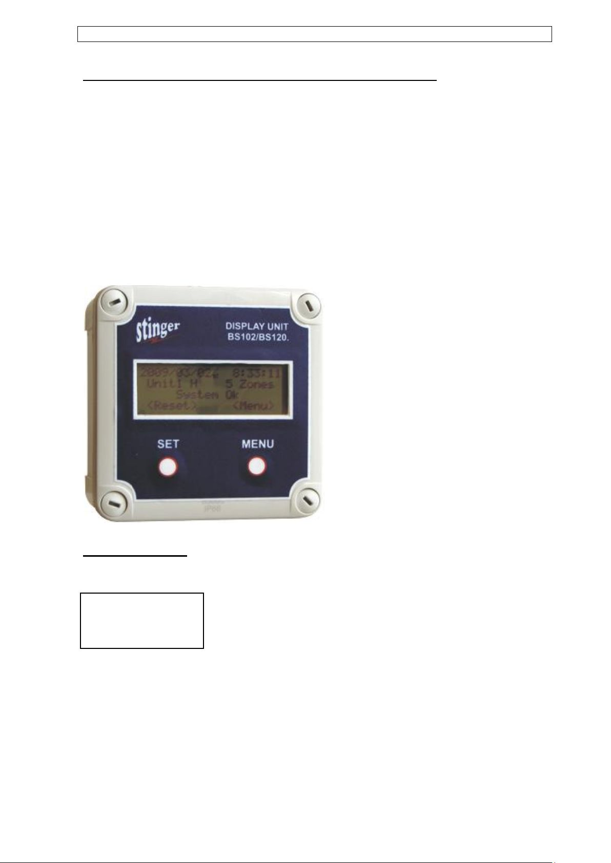
The output voltage of each energizer can be viewed at the LCD Panel and will also be
logged via the computer program.
The software allows for pulse synchronisation of multiple BS120 units.
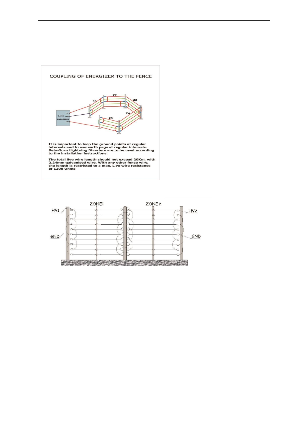
The zones have to be series wired and must be series connected to each other.
The start and end points of the fence and the fence ground are the only
connections to the energizer. An additional feature is that the fence is powered from
both ends.
An auto-reset facility is available and can be enabled or disabled. The unit will
automatically try to reset an alarm after 3 minutes. If successful, the alarm was
apparently a nuisance alarm and no further action is required.
SPECIFICATIONS
Power
Input Voltage :110V-250V AC or 12V DC (Solar Panel)
Power Consumption :15VA
Built-in back-up Battery :7.5 A/H, 12V Lead Acid Battery.
Back-uptime> 5 hours
HV Output (High mode)
Output Voltage (open) : 8250V
Output Voltage (500 Ohms) : 7500V
Output Voltage (100 Ohms) : 6000V
Output pulse Energy : 7.5 J
Output pulse length (10% points) : 130s
Pulse Repetition Rate : 1.2 S
HV Output (Low mode) : 800V
Output pulse energy : 0.08 J
Max. length of live wire : 25 Km with max. wire resistance of
1000 Recommended < 500 Ohms)
Dimensions : 340 X240 X 130
Weight : 4kG
Watchdog
Built-in watchdog to prevent double pulsing and to limit max. Energy output.
The energizer will switch off if any of these conditions will occur and
will be indicated at the energizer board by leds.
The system complies with the following specifications:
IEC 60335-1, IEC 60335-2-76, IEC1000-3-2, IEC 61326-1, CISPR Pub. 14.
The system has been CE approved by the SABS, and the
CEcertificate is available on request.

STINGER ELECTRONICS (PTY) LTD BS120 INSTRUCTION MANUAL REF:03/2018
Printed: 4/26/2019 Page 3of 20
Control Inputs/Outputs on the Energizer unit:
External Siren connection : Contacts available for 12V/10W Siren. On—Time3 minutes or
terminated on “reset”.
Silent alarm connection : Contacts available for a 12V, max 1A load.System has to be reset
before a new alarm can be triggered.
Gate monitor connection : Input for n/c gate contact.
Alarm system : HV current monitoring system. A sequence of 3 identical faults
occurring in the same zone isrequired before an alarm condition will be
reported.
WINDOWS SOFTWARE PACKAGE
This package has been specifically designed for the ”Stinger” BS120 system, used on large sites with a
number of ”Stinger” units. The software is extremely versatile and is yet user friendly to the average
operator.
The program has the following general features
Can be loaded onto all modern machines and is Windows95/98/2000/NT/XP
compatible.
Communicates via the computer comm. port and
an RS485 to RS232 converter with up to 125 BS120 units via a two wire cable, RF data link or fibre optic
cable.
Full control of all units is possible via simple configure and setting-up windows.
Up to 125 site maps can be imported, indicating on the screen the physical positions of the”Stinger”
units and the Electric fence zones at the perimeter.
The location and the type of alarm condition will be shown at the site map for quick reaction by the
security personnel.
An alarm will be raised to alert the operator.
Feedback systems are built into the software to monitor the reactions of the
operating personnel.
A log file keeps record of all events and fence conditions and is available for later
retrieval. A printout can be made anytime of any part of this file.
Extensive protection in the software to counteract tampering with logged data.
The HV outputs of ”Stinger” units can be individually programmed to switch to high or low voltage at
selectable times and days.
It is possible via this program to synchronise a number of BS120 units to comply with Government
regulations.
The contents of the “Log file” can be downloaded to a remote computer if a telephone modem has been
installed.
Optional peripherals
-Mains modem for activating floodlights per zone or to communicate with a remote control unit via
mains communication.
-600 mW UHF TransceiverWith FSK modem. Can be used for data communication overdistances
up to 4 Km and more.
-Relay card. Provides 25 relay contact outputs for interfacing to e,g, existing alarm system, lights
etc.
-Stinger program extension is available to provide full SMS facility.

STINGER ELECTRONICS (PTY) LTD BS120 INSTRUCTION MANUAL REF:03/2018
Printed: 4/26/2019 Page 4of 20
Earthing practice
The above picture indicates how earthing should be done. This
picture only shows the earthing required to protect the energizer
against lightning. General fence earthing depends on external
factors like ground conduction etc.
Zone length: The best results will be obtained it the difference in
zone resistance is not more than 50%

STINGER ELECTRONICS (PTY) LTD BS120 INSTRUCTION MANUAL REF:03/2018
Printed: 4/26/2019 Page 5of 20
INSTALLATION TIPS:
The following tips will help to facilitate installation.
1 Using the best type of bobbins and strain insulators will result in a trouble
free installation. E.g. Stinger strain insulators and Stinger intermediate bobbins.
2 Using low resistance aluminum wire will result in effective shock delivery.
3 Grounding the fence at regular intervals results in high stability and better
shock delivery .
4 Early morning false alarms occur due to arcing. Check the fence currents
with the display unit in the Power mode. If the HV1 and HV2 values are
unstable, there is a weak point somewhere at the fence. (Cracked bobbin,
too short wire spacing at stays etc.).
5 Keep HT wires away from communication- and power cables.
6 Underground HT Cables should be mounted inside irrigation tubing/conduit.
7 If the distance between the fence and the location of the energizer is long,keep the
two HT wires separated by 200mm. Use braided bare copper for the ground wire,
burying it directly in the ground. This will ensure the best eathing possible.
If the distance between energizer and control unit is more than 10 meters, it is wise
to mount a copper braided cable together with the comms cable.Ground this copper
cable at both end points.
The following table shows the effect of the type of fence wire used in relation to
practically obtainable distances.
Fence wire resistance and compatibility with the BS120.
Type of wire
Resistance (Ω/Km)
Max tolerable live wire length
L(1/2V)*
Stainless 1.2mm
770
1.9 Km
0.65 Km
Braided 1.0mm
330
4.5 Km
1.6 Km
Braided 1.3mm
260
5.7 Km
1.9 Km
Galv steel 1.57mm
100
15 Km
5 Km
Galv steel 2.24 mm
50
30 Km (Practical limit 25 Km)
10 Km
Alu. 1.6mm
27
44 Km (Practical limit 25 Km)
13.5 Km
Alu 2.4 mm
9
133 Km (Practical limit 25 Km)
55 Km
*The value L(1/2V) is that length of live wire, where half of the energizer output
voltage drops across the fence wire and the other half across a person touching
thewire at distance L(1/2V). (Equals to only 25% of the potential energy at the
energizer output. This value relates to any energizer being used. The
resistance of ahumanbody has been standardized at 500 Ohms.)
8 Fence monitor lights : Recommended maximum three per BS120 Energizer, as each
fence monitor light draws +-0,4J.

STINGER ELECTRONICS (PTY) LTD BS120 INSTRUCTION MANUAL REF:03/2018
Printed: 4/26/2019 Page 6of 20
FENCE WIRING EXAMPLES
It is important to always loop the earth wires together at each zone
split.This will ensure maximum energy transfer.
For extremely long fences, or in situations where the fence
resistance becomes excessive high, wires can be connected
inparallel. It is in this case important that the parallel connections
are repeated at the end of each zone as shown above.
For more information please refer to “Stinger Specification for construction of
electric fencing” available on request.

STINGER ELECTRONICS (PTY) LTD BS120 INSTRUCTION MANUAL REF:03/2018
Printed: 4/26/2019 Page 7of 20
Long fences can be operated with multiple energizers, provided these units are
synchronized.
Stinger has SABS approval for such a system. Each energizer can feed one live wire.
The advantage of this system is that no trenching, cabling or solar panels are required,
as all units are located inside the guard house.
An additional advantage is the fact that the fence is much more secure in case of one
of the energizers failing.
Fences with a total circumference of 10 Km have been wired according to this system.
Sync Unit or
LCD Keypad
handling
multiple
energizers.

STINGER ELECTRONICS (PTY) LTD BS120 INSTRUCTION MANUAL REF:03/2018
Printed: 4/26/2019 Page 8of 20
OPERATING INSTRUCTIONS
Zone programming
Before starting, check the following fence conditions (with the HV wires
disconnected):
1. The DC resistance of the HV loop must be lower than 1200 Ohms.
2. The DC resistance between GND and the live wires must be higher than
100000 Ohms.
Programming
1. Switch the Energizer on to High Voltage Mode.
2. Press the “Program” button for 5 seconds. If the buzzer sounds, there is
a fence problem, which must be solved first. The problem may be a short
circuit or arcing.
3. Make a short circuit at zone split 1-2 (use the cable with crocodile clips),
the buzzer will sound, press the “Accept” button briefly.
4. Repeat step 3 until all zones have been programmed. After the last zone
press “Program” again to leave this routine. The remote control unit will
indicate the program status.
Remote Control Unit Connections
The standard connection cable can be extended to a length of a 100m.
This can be safely done if lightning in that area is not a problem.
Otherwise add a braided copper wire to the cable, which must be earthed at
both sides.
For longer distances the “Stinger” data radio should be used.
USE STINGER LIHGTNING DIVERTERS BETWEEN THE ENERGIZER GND CONNECTION AND THE
HV1 AND HV2 OUTPUTS.
USE A MAINS LIGHTNING PROTECTOR AT THE MAINS INPUT TO THE UNIT.
Connections
connector block:
1. Gate switch
2. Gate switch
3. Strobe light +
4. Strobe light –
5. Siren +
6. Siren -
Please note:
-The instrument is to be installed inside a building
or inside a water tight enclosure.
-No external apparatus to be connected to the
energizer power source (battery).
1 2 3 4 5 6
CONNECTOR BLOCK
BATTERY
ENERGIZER
PROGRAM
ACCEPT
1 2 3 4
Remote Control
Pc Board
4 Ln2 (green)
3 Ln1 (white)
2 + 12V (red)
1 Gnd (black)
HV 1
HV 2
GND
MONITOR
HT XFMR
CT UNIT

STINGER ELECTRONICS (PTY) LTD BS120 INSTRUCTION MANUAL REF:03/2018
Printed: 4/26/2019 Page 9of 20
The BS120/BS102 control unit has the following features:
1 Can communicate with up to 13 BS120/BS102 units
2 Will automatically synchronize the HT pulse delivery of multiple energizer
units.
3 Can be configured for master or slave mode.
4 RS485 communication protocol.
5 Built-in time and date generator.
6 99 events memory. Data can be retrieved via LCD screen.
7 Pin protected user menu and -installer menu.
8 All energizer settings can be addressed via the keypad.
9 The BS120/BS102SMS control unit features an optional built-in modem
with full SMSout capability.
1 Fault Messages
Normal Display
Normal indication with a properly working fence.
It indicates that the unit’s address is nr. 1, it has been programmed for 20 zones, the fence
voltage is in the high (H)mode and the system is working properly.
The time and date indication is used for the event memory.
2007/01/01 0:00:17
UNIT1 H 20 ZONES
System OK
(RESET) (MENU)

STINGER ELECTRONICS (PTY) LTD BS120 INSTRUCTION MANUAL REF:03/2018
Printed: 4/26/2019 Page 10 of 20
THE FOLLOWING FAULTS CAN BE DISPLAYED:
The system is in the HIGH voltage mode and has detected that the live wire has been cut,
resulting in an open circuit indication. Pressing “reset” will silence the built-in buzzer, but the
problem needs to be resolved first before the screen will return to normal.
The system is in the LOW voltage mode and has detected that the live wire has been cut,
resulting in an open circuit indication. Pressing “reset” will silence the built-in buzzer, but the
problem needs to be resolved first before the screen will return to normal.
The systemis in the HIGH voltage mode and has detected that the livewire is touching a ground
wire in zone 2, resulting in a short circuit indication. Pressing “reset” will silence the built-in
buzzer, but the problem needs to be resolved first before the screen will return to normal.
The systemis in the LOW voltage mode and has detected that thelivewire is touching a ground
wire in zone 2, resulting in a short circuit indication. Pressing “reset” will silence the built-in
buzzer, but the problem needs to be resolved first before the screen will return to normal.
The system has detected that it is not possible to communicate with unit 1. Pressing “reset” will
silence the built-in buzzer, but the problem needs to be resolved first before the screen will
return to normal.
Mains Failure detection for unit 1. Theenergizer is now running from the battery for a limited
period of time.
2007/01/01 0:00:17
UNIT1 H 20 ZONES
! Open Circuit !
(RESET) (MENU)
2007/01/01 0:00:17
UNIT1 L 20 ZONES
! Open Circuit !
(RESET) (MENU)
2007/01/01 0:00:17
UNIT1 H ZONE 2
!Short Circuit !
(RESET) (MENU)
2007/01/01 0:00:17
UNIT1 L Zone 2
! Short Circuit !
(RESET) (MENU)
2007/01/01 0:00:17
UNIT1 !!!
No communication
(RESET) (MENU)
2007/01/01 0:00:17
UNIT1 H 20 Zones
! Mains Failure !
(RESET) (MENU)
2007/01/01 0:00:17
UNIT1 H 20 Zones
! BatteryLow !
(RESET) (MENU)

STINGER ELECTRONICS (PTY) LTD BS120 INSTRUCTION MANUAL REF:03/2018
Printed: 4/26/2019 Page 11 of 20
Battery low indication. The battery voltage is down to a critically low level, the unit will switch
off sometime in the next few hours.
The HT voltage at unit 1 is too low (lower than 3000 Volt) due to a system fault.
Gate open alarm. Will operate only if the gate inputs at the energizer are connected to a gate
switch.
2 User Menu BS120
To enter the user Menu, press “Menu” for 2 seconds.
To enter the user menu, the pin code must be entered first(if menu pin is enabled in the
advanced menu). The default code is 0000, which can also be changed in the advanced menu. To
enter the code, press the “increase” button to increment the display to reach the first correct
digit. Press “next key” and repeat for the second digit etc. The pin code can also be disabled in
the advanced menu.
To switch the HT voltage to the low voltage mode, press the “low” button. The unit will now
carry-on at an output voltage of 800V. This feature is useful in case of a school installation
where children are present during the day.
The display back-light can be switched on/off in this menu.
Whenswitched off, it will always switch-on when a button is activated or if there is an alarm to
be displayed.
2007/01/01 0:00:17
UNIT1 H 20 Zones
! HT Failure !
(RESET) (MENU)
- - - - -- -User Menu- - - - - - - - - 1
Enter Menu pin
0 _ _ _
(Increase) (Next Menu)
- - - - - -User Menu- - - - - - - - - 2
Energizer HV output
High
(Low) (Next Menu)
- - - - - - -User Menu- - - - - - - - - 3
Display Backlight
On
(Off) (Next Menu)
- - - - - - -User Menu- - - - - - - - - 4
Siren Output
Enabled
(Disabled) (Next Menu)
2007/01/01 0:00:17
UNIT1 H 20 Zones
! Gate open !
(RESET) (MENU)

STINGER ELECTRONICS (PTY) LTD BS120 INSTRUCTION MANUAL REF:03/2018
Printed: 4/26/2019 Page 12 of 20
Enabling or disabling the siren output, will only control the external siren. The internal buzzer
will always remain active.
If the control unit is connected to more than one energizer, pressing “read” repeatedly will show
the fence voltage at each energizer. (FB’s – Field Boxes)
To read the event log file
Press “read” to read the first event
Press next line to read the subsequent events (a Maximum of 100 events are stored.
Exit the user menu. New settings will only come into effect after exiting the menu.
3 Advanced Menu BS120(Press both keys simultaneouslyfor3 seconds)
Enter the advanced menu pin code. (Default pin is 1111.)
The following screen languages can be selected: English and Dutch.
Press ”select” to enter this Menu.
- - - - - - -User Menu- - - - - - - - -7
Save Settings
and exit Menu
(Exit) (Menu)
- - - - - - User Menu- - - - - - - - - 5
Read Fence Voltage
output = 6900 V
(Read) (Next Menu)
0-100 - - User Menu- - - - - - - - - 6
Read Event Log
(Read) (Next Menu)
- - - --- Advanced Menu- - - - - - 1
Enter Pin Code
0 - - -
(Increase) (Next Key)
- - - --- Advanced Menu- - - - - - 3
Read and change
calibration values
(Select) (Next Menu)
- - - --- Advanced Menu- - - - - 3.1
Select Unit to
configure: FB1
(Increase) (Enter)
1-100 - - User Menu- - -- - - - 6.1
2008-06-23 23:32
FB1 Short Circuit Zone 5
(Next line) (Next Menu)
- - - --- Advanced Menu- - - - - - 2
Select Language
English
(Change) (Next Menu)

STINGER ELECTRONICS (PTY) LTD BS120 INSTRUCTION MANUAL REF:03/2018
Printed: 4/26/2019 Page 13 of 20
Select the unit you want to configure and press “enter”.
The system has detected that the display unit has been connected to a BS120 energizer. Press
“continue” to proceed.
In power mode, you can read the HT currents, which are flowing from the energizer into
the fence wires.
By pressing incr. level, the Short circuit level can be increased. This can be done if the
current readings are very high, due to high fence capacitance.
A short circuit alarm will be given if the sum of the HT current readings is higher than the
Short level setting for three consecutive faults in the same zone. Press “select” to read the
present current values.
Press “select” to read the programmed zone current values, which are stored in the micro-
processor memory.
The programmed currents for each zone can be read by pressing “next”.
The currents programmed in a zone can be changed by pressing “select”.
- - - --- Advanced Menu- - -- 3.2
Poling Unit 1 please
wait ……..
(Cancel) (Next Menu)
- - - --- Advanced Menu- - - - 3.4
Enter ‘Power mode’
for reading currents
(Select) (Next Menu)
- - - --- Advanced Menu- - - - 3.5
Read programmed
Zone currents
(Select) (Next Menu)
- - - --- Advanced Menu- - - - 3.10
FB1 HV1=8 HV2=10
Short Level = 106
(Incr Lev) (Next)
- - - --- Advanced Menu- - - - 3.6
Change programmed
Zone currents
(Select) (ExitConf)
- - - --- Advanced Menu- - - - 3.17
FB1 Zone 1
HV1 = 255 HV2 =13
(Next) (ExitConf)
- - - --- Advanced Menu- - - - 3.3
A BS120 energiser
was found, continue ?
(Retry) (Continue)

STINGER ELECTRONICS (PTY) LTD BS120 INSTRUCTION MANUAL REF:03/2018
Printed: 4/26/2019 Page 14 of 20
First select the zone to be changed by pressing “Increase”
Change stored current values on HV1 or HV2 for this zone.
Increase the HV1 value for the zone if needed.
Increase the HV2 value for the same zone if needed.
The LCD keypad is by default set to “master” mode. It can be changed to the slave mode by
pressing the “slave” button. Up to 20 LCD keypad units can be connected to the RS485
communication line.
In auto “reset” mode, the unit will try to “reset” itself after an alarm condition has been
announced. To disable this function, press “disable”.
The communication speed is by default set to a baud rate of 2400. This baud rate is valid for
wire- or Fibre-optic communication. For radio communication change the baud rate to a value of
1200 by pressing “change”.
- - - --- Advanced Menu- - - - 4.0
Remote Mode
Master
(Slave) (Next Menu)
- - - --- Advanced Menu- - - - -5.0
Auto “reset” mode
Enabled
(Disable) (Next Menu)
- - - --- Advanced Menu- - - - - 6.0
Set Comms Mode
2400 Baud (Cable/F.O.)
(Change) (Next Menu)
- - - --- Advanced Menu- - - - 3.7
Select zone to
Change, zone5
(Increase) (Accept)
- - - --- Advanced Menu- - - - 3.8
Select HV1 or HV2
To be changed
(HV1) (HV2)
- - - --- Advanced Menu- - - - 3.9
Insert new value
For zone5: 3 HV1
(Increase) (Next)
- - - --- Advanced Menu- - - - 3.9
Insert new value
for zone 5: 3 HV2
(Increase) (Next)

STINGER ELECTRONICS (PTY) LTD BS120 INSTRUCTION MANUAL REF:03/2018
Printed: 4/26/2019 Page 15 of 20
With only one energizer connected, the LCD keypad will send the broadcast address “255”. If
the address of this energizer has not been modified, it will reply with the address 0. Else it will
reply with the modified address. (visible on the home screen and in menu 3.1.3,(Field box number
–1 = address)).
If more than one energizer has been connected to the LCD keypad, a synchronization signal is
automatically sent to all energizers(not via Radio in the 1200 Baud mode).
To stop synchronization, press “disable”.
Use this menu to select the number of energizers connected to the LCD keypad.
This menu allows the user to change the address of an energizer. Press “select” to enter
this menu.
If the hard- or software address of the energizer is unknown, select “yes” to use the broadcast
address, otherwise press “no” to enter the destination address.
Press “increase” until the current address value is reached, followed by “Accept”
”
Press “increase” until the new destination address value is reached, followed by “Accept”
This menu confirms the address change. (yes)
- - - --- Advanced Menu- - - - - - 8
Number of Energizers
1
(Increase) (Next Menu)
- - - --- Advanced Menu- - - - - - 9
Send new address
to a unit
(Select) (Next Menu)
- - - --- Advanced Menu- - - - -9.1
Use broadcast
Address? (255)
(Yes) (No)
- - - --- Advanced Menu- - - - - 9.4
Send new address 0
to address 255??
(Yes) (No)
- - - --- Advanced Menu- - - - - 7.0
Sync Energizers
Enabled
(Disable) (Next Menu)
- - - --- Advanced Menu- - - - - 9.5
Address change √
New address = 0
(Yes) (No)
- - - --- Advanced Menu- - - - - 9.3
Insert new
Address => 0
(Increase) (Next)
- - - --- Advanced Menu- - - - -9.2
Insert destination
Address = >0
(Increase) (Next)

STINGER ELECTRONICS (PTY) LTD BS120 INSTRUCTION MANUAL REF:03/2018
Printed: 4/26/2019 Page 16 of 20
If you want to cancel the address change in case of a mistake, press “no”
This menu confirms cancellation of the address change procedure.
Press select to change system date or time.
Press “year” repeatedly to reach the correct year.
Press “Month” to reach the correct month.
Press “Day” to reach the correct day.
Press “Hour” to reach the correct Hour
Press “Minute” to reach the correct Minute.
- - - --- Advanced Menu- - - - 10.0
Set time & date
2000/01/01 0:32:48
(Select) (Next Menu)
- - - --- Advanced Menu- - - - - 9.6
Address change X
Cancelled by user
(Redo) (No)
- - - --- Advanced Menu- - - - 10.1
Set time & date
2000/01/01 0:32:48
(Year) (Go to month)
- - - --- Advanced Menu- - - - 10.2
Set time & date
2000/01/01 0:32:48
(Month) (Go to day)
- - - --- Advanced Menu- - - - 10.4
Set time & date
2000/01/01 0:32:48
(Hour) (Go to minute)
- - - --- Advanced Menu- - - - 10.5
Set time & date
2000/01/01 0:32:48
(Minute) (Go to second)
- - - --- Advanced Menu- - - - 10.3
Set time & date
2000/01/01 0:32:48
(Day) (Go to Hour)
- - - --- Advanced Menu- - - -10.6
Set time & date
2000/01/01 0:32:48
(Seconds) (Finish)

STINGER ELECTRONICS (PTY) LTD BS120 INSTRUCTION MANUAL REF:03/2018
Printed: 4/26/2019 Page 17 of 20
Press “Seconds” to reach the correct Second.
Press “redo” if you want to repeat the above operation or press “next menu” to proceed.
Press “Select” if you want to change the pin number for the advanced menu.
Set the new Advanced Pin code.
Confirm the new Advanced PIN code and save or Re-enter.
Enable or disable the PIN code for the standard Menu
Select to change the PIN code of the standard Menu
Select the new PIN code by pressing “increase” and “next key”
- - - --- Advanced Menu- - - - 11.0
Change adv. PIN?
(Redo) (Next Menu)
- - - --- Advanced Menu- - - - 11.2
Change adv. PIN to
0000?
(Re-enter) ( save)
- - - --- Advanced Menu- - - - 12
Menu Pin enabled?
Enabled
(Disable) (Next Menu)
- - - --- Advanced Menu- - - - 10.7
Set time & date
2000/01/01 0:32:48
(Redo) (Next Menu)
- - - --- Advanced Menu- - - - 11.1
Change adv. PIN to
0---
(Increase) (Next Key)
- - - --- Advanced Menu- - - - 13
Change menu PIN?
(Select) (Next Menu)
- - - --- Advanced Menu- - - - 13.1
Change menu PIN to
0----
(Increase) (Next Key)

STINGER ELECTRONICS (PTY) LTD BS120 INSTRUCTION MANUAL REF:03/2018
Printed: 4/26/2019 Page 18 of 20
Press “Save” to accept the new PIN Code. Re-enter to redo.
OPTIONAL MENU FOR THE BS120/BS102 LCD keypad with SMS modem installed.
Press “Select” to enter this menu.
Press “Select” to change the Site name.
Press “Next menu”to enter SMS users
Press select to add or change user data.
- Press Change to Enable/Disable and edit the name and number.
- Between these first brackets the user can be enabled []or disabled [x].
- Each character of the name must be entered or changed individually. Repeated pressing
“change” will change the “name” characters from “no character” to “A” to “Z”. Press
“NextMenu”to select the following character. After the last character press “Next Menu”
repeatedly to arrive at the first character of the phone number.
- Repeated pressing “change” will change the “number” characters from “no number” to “9”. A
number can be entered with/without the land code (+27) in front of the number.
-If one has made a mistake, keeping set button depressed and then pressing menu button will
reverse editing direction thus one can go back to correct the mistake.
-After the number has been entered, press “NextMenu” repeatedly to arrive at the “user 2”
screen. Enter the details etc. The max. number of users is 25. (Only 13 smses can be send at
once per alarm, thus it does not make sense to let all 25 users get a specific alarm, as only the
first 13 users will get that alarm.)
- - - --- Advanced Menu- - - - 13.2
Change menu pin to
0000??
(ReEnter) (Save)
- - - --- Advanced Menu- - - - 14.0
SMS Settings
(Select) (Next Menu)
- - - --- Advanced Menu- - - - 14.2
SMS Users
(Select) (Next Menu)
User 1 AdMenu 14.2
[] WOUTER
Nr: 0831234567
(Change) (Next Menu)
- - - --- AdvancedMenu- - - 14.1
Site Name
Church Street 35
(Change) (Next Menu)

STINGER ELECTRONICS (PTY) LTD BS120 INSTRUCTION MANUAL REF:03/2018
Printed: 4/26/2019 Page 19 of 20
Press “Select” to assign alarm types to each user starting with user 1.
*Selectable messages per user are listed at the bottom of this page.
By default all alarm types are assigned to a user. Pressing “Change” will change the status and
the “” mark” to a “X” mark.
Alarm reset function*:
Users for which the Reset“” has been enabled, will be able to phone the modem from their cell
phone to reset alarms (SMS Simcard must have “caller identity” enabled, and users that call in
must have their number show up for the modem to recognise their number) . The user will hear
an intermittent tone (every 2-3sec) if an alarm exists, which indicates that the energizer is
trying to reset the alarm. If it was a temporary alarm, the energizer will reset and the
intermittent tone will stop. If the alarm cannot be reset, the intermitted tone will carry on until
the connection is terminated. The call will automatically be terminatedafter 30s.
*PS: After a “call in”the modem will always send an info/status message to the user.
Press “Exit” to save settings and exit the menu, or press “Advanced Menu” to go back to the
first advanced menu.
Alarms that SMS messages can be send for and enabled/disabled:
Z1[x]…Z20[x] For the BS120 Zone 1 - Zone 20.
Nocomms[x] No communication with unit (E.g. BS102, BS120 CDS or UDS unit)
FenceV.L[x] For BS120/BS102 The High Voltage is < 3000V due to an energizer failure.
Batt.L[x] Battery voltage is < 11.2V. (Normally under charge > 13 Volts)
Mains.F[x] For BS102 Mains Voltage interrupted (N/A for BS120)
OpenCt1[x] For BS120 Open circuit of live HT loop, For BS102 Zone 1 open circuit.
ArcZ1[x] For BS102 Zone1 HV arcing to ground.
ShortZ1[x] For BS102 Zone 1 Full short to ground.
GndZ1[x] For BS102 Zone 1 Ground loop broken.
OpnZ2[x] For BS102 Zone 2 open circuit.
ArcZ2[x] For BS102 Zone2 HV arcing to ground.
ShrtZ2[x] For BS102 Zone 2 Full short to ground.
GndZ2[x] For BS102 Zone 2 Ground loop broken.
Aux1-Aux6[x] For BS120/BS102 Aux1 is aux/gate input alarm for FB1, Aux2 for FB2 etc.
Reset[x] If this is enabled, this user will be able to reset an alarm by phoning the modem
number, the modem will then answer and reset the alarm. (Explained above under
heading (Alarm reset function:)
CDSdet[x] For CDS/UDS detection alarm.
-Advanced Menu- 14.4
User Alarms
(Select) (Next Menu)
-User 1 AdMenu- 14.4
[] WOUTER
Z1 Z2Z3Z4etc.
(Select) (Next Menu)
- - - --- Advanced Menu- - - - 15
Save settings
and exit adv. Menu
(Exit) (Advanced Menu)

STINGER ELECTRONICS (PTY) LTD BS120 INSTRUCTION MANUAL REF:03/2018
Printed: 4/26/2019 Page 20 of 20
LIMITED WARRANTY BS120 Electric Fence Energizer.
Stinger Electronics will repair or replace* your product at our discretion
without charge, if it proves to be defective, in material or workmanship
under use, during the warranty period of one year from the date of original
purchase.
The client is responsible for the transport of the unit to and from
the premises of Stinger TM Electronics.
THE ABOVE WARRANTY DOES NOT APPLY IN CASE OF:
1 Damages or problems which result from delivery or improper installation.
2 Damages to the product caused by accident, vermin, fire, flood, alteration
misuse or lightning.
3 To service calls and to explaining the working of the unit.
4 If the serial number of the unit is defaced or missing.
Therefore these costs are to be paid by the owner.
* Replacement is a factory-reconditioned unit. Free replacement applies
only within the initial one-year period. Factory-reconditioned units may be
available at a lower, fixed cost after the one-year warranty period has
expired.
No other express warranty is applicable to this product.
THE DURATION OF IMPLIED WARRANTIES, INCLUDING THE IMPLIED
WARRANTY OF MERCHANTABILITY, IS LIMITED TO THE DURATIO
N
OF THE EXPRESS WARRANTEE HEREIN. WE SHALL NOT BE LIABLE FOR
THE LOSS OF THE USE OF THE PRODUCT, INCONVENIENCE, LOSS OR
ANY OTHER DAMAGES, DIRECT OR CONSEQUENTIAL, ARISING OUT
OF THE USE OF, OR INABILITY TO USE, THIS PRODUCT OR FOR ANY
BREACH OF ANY EXPRESS OR IMPLIED WARRANTEE, INCLUDING THE
IMPLIED WARRANTEE OF MERCHANTABILITY APPLICABLE TO THIS
PRODUCT.
Although the information (specifications, contacts, etc) was correct at
the time of printing, anything in the user’s manual is subject to change
without prior notice.
N.B. The backup battery carries no warranty.
Table of contents
Other Stinger Power Supply manuals