STMicroelectronics UM2322 User manual

March 2018 UM2322 Rev 2 1/22
1
UM2322
User manual
STM32 Discovery pack for 2G/3G cellular to cloud
Introduction
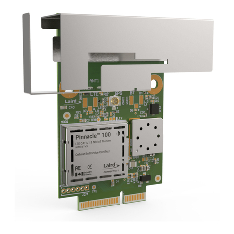
The STM32 Discovery pack (P-L496G-CELL01) is a turnkey development platform for
cellular and cloud technology based solutions. The pack contains an STM32L496AGI6-
based low-power Discovery mother board and an STMod+ Cellular 2G/3G worldwide
expansion board with antenna.
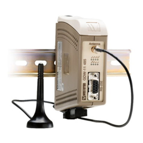
Figure 1. P-L496G-CELL01 (Top view)
1. Picture is not contractual.
www.st.com

Contents UM2322
2/22 UM2322 Rev 2
Contents
1 Features . . . . . . . . . . . . . . . . . . . . . . . . . . . . . . . . . . . . . . . . . . . . . . . . . . . 5
2 System requirements . . . . . . . . . . . . . . . . . . . . . . . . . . . . . . . . . . . . . . . . 6
3 Development toolchains . . . . . . . . . . . . . . . . . . . . . . . . . . . . . . . . . . . . . . 6
4 Demonstration software . . . . . . . . . . . . . . . . . . . . . . . . . . . . . . . . . . . . . . 6
5 Ordering information . . . . . . . . . . . . . . . . . . . . . . . . . . . . . . . . . . . . . . . . 6
6 Technology partners . . . . . . . . . . . . . . . . . . . . . . . . . . . . . . . . . . . . . . . . . 7
7 Hardware layout and configuration . . . . . . . . . . . . . . . . . . . . . . . . . . . . . 8
7.1 Board layouts . . . . . . . . . . . . . . . . . . . . . . . . . . . . . . . . . . . . . . . . . . . . . . . 8
7.2 Cellular STMod+ expansion board . . . . . . . . . . . . . . . . . . . . . . . . . . . . . . . 9
7.2.1 Modem power supply and reset . . . . . . . . . . . . . . . . . . . . . . . . . . . . . . . 10
7.2.2 SIM selection . . . . . . . . . . . . . . . . . . . . . . . . . . . . . . . . . . . . . . . . . . . . . 10
7.2.3 Modem firmware update. . . . . . . . . . . . . . . . . . . . . . . . . . . . . . . . . . . . . 10
7.3 Embedded ST_LINK/V2-1 . . . . . . . . . . . . . . . . . . . . . . . . . . . . . . . . . . . . .11
7.3.1 Drivers . . . . . . . . . . . . . . . . . . . . . . . . . . . . . . . . . . . . . . . . . . . . . . . . . . 11
7.4 Mother board power supply . . . . . . . . . . . . . . . . . . . . . . . . . . . . . . . . . . . .11
7.4.1 Power supply sources . . . . . . . . . . . . . . . . . . . . . . . . . . . . . . . . . . . . . . 11
7.5 Mother board reset sources . . . . . . . . . . . . . . . . . . . . . . . . . . . . . . . . . . . 12
7.6 Mother board boot options . . . . . . . . . . . . . . . . . . . . . . . . . . . . . . . . . . . . 12
Appendix A Expansion board schematics . . . . . . . . . . . . . . . . . . . . . . . . . . . . . . 14
Appendix B Federal Communications Commission (FCC)
and Industry Canada (IC) Compliance . . . . . . . . . . . . . . . . . . . . . . . 20
Revision history . . . . . . . . . . . . . . . . . . . . . . . . . . . . . . . . . . . . . . . . . . . . . . . . . . . . 21

UM2322 Rev 2 3/22
UM2322 List of tables
3
List of tables
Table 1. Ordering information . . . . . . . . . . . . . . . . . . . . . . . . . . . . . . . . . . . . . . . . . . . . . . . . . . . . . . . 6
Table 2. STMod+ connector pin description . . . . . . . . . . . . . . . . . . . . . . . . . . . . . . . . . . . . . . . . . . . . 9
Table 3. Boot settings . . . . . . . . . . . . . . . . . . . . . . . . . . . . . . . . . . . . . . . . . . . . . . . . . . . . . . . . . . . . 12
Table 4. Document revision history . . . . . . . . . . . . . . . . . . . . . . . . . . . . . . . . . . . . . . . . . . . . . . . . . 21

List of figures UM2322
4/22 UM2322 Rev 2
List of figures
Figure 1. P-L496G-CELL01 (Top view) . . . . . . . . . . . . . . . . . . . . . . . . . . . . . . . . . . . . . . . . . . . . . . . . 1
Figure 2. Mother board and expansion 2G/3G modem top view . . . . . . . . . . . . . . . . . . . . . . . . . . . . . 8
Figure 3. Mother board and expansion 2G/3G modem bottom view . . . . . . . . . . . . . . . . . . . . . . . . . . 9
Figure 4. USB Composite Device driver installation. . . . . . . . . . . . . . . . . . . . . . . . . . . . . . . . . . . . . . 11
Figure 5. Expansion board top level . . . . . . . . . . . . . . . . . . . . . . . . . . . . . . . . . . . . . . . . . . . . . . . . . 15
Figure 6. Expansion board modem . . . . . . . . . . . . . . . . . . . . . . . . . . . . . . . . . . . . . . . . . . . . . . . . . . 16
Figure 7. Expansion board SIM . . . . . . . . . . . . . . . . . . . . . . . . . . . . . . . . . . . . . . . . . . . . . . . . . . . . . 17
Figure 8. Expansion board STMod+ . . . . . . . . . . . . . . . . . . . . . . . . . . . . . . . . . . . . . . . . . . . . . . . . . 18
Figure 9. Expansion board power . . . . . . . . . . . . . . . . . . . . . . . . . . . . . . . . . . . . . . . . . . . . . . . . . . . 19

UM2322 Rev 2 5/22
UM2322 Features
21
1 Features
•STM32L496AGI6 Arm®-based microcontroller featuring 1 Mbyte of Flash memory and
320 Kbytes of RAM in a UFBGA169 package
•USB OTG HS
•On-board current measurement
•SAI Audio CODEC
•ST-MEMS digital microphones
•8-Mbit PSRAM
•2 user LEDs
•1 user and 1 reset push-buttons
•4-direction joystick with selection button
•Board connectors:
– Camera 8 bit
– USB with Micro-AB
– Stereo headset jack including analog microphone input
– microSD™ card
•Board expansion connectors:
– Arduino™ Uno V3
–STMod+
•Board expansion features:
– Quectel UG96 worldwide cellular modem penta-band 2G/3G module, 7.2 Mbps
downlink, 5.76 Mbps uplink.
– Modem reset red LED and modem signaling green LED
– Switchable SIM interface, eSIM and micro SIM
– Pulse 2G/3G SMA antenna for frequency ranges: 824 / 900 / 1800 / 1900 / 2100 MHz
•Flexible power-supply options: ST-LINK, USB VBUS, or external sources
•On-board ST-LINK/V2-1 SWD,TAG debugger/programmer with USB re-enumeration
capability: mass storage, virtual COM port and debug port
•Comprehensive free software libraries and examples available with the STM32Cube
package
•Support of a wide choice of integrated development environments (IDEs) including IAR™,
Keil®, GCC-based IDEs

System requirements UM2322
6/22 UM2322 Rev 2
2 System requirements
•Windows®OS (7, 8 and 10), Linux®64-bit or macOS®
•USB Type-A to Micro-B cable
3 Development toolchains
•Keil®MDK-ARM(a)
•IAR™ EWARM(a)
•GCC-based IDEs including free SW4STM32 from AC6
4 Demonstration software
The demonstration software, included in the STM32Cube MCU Package, is preloaded in the
STM32 Flash memory for easy demonstration of the device peripherals in standalone mode.
The latest versions of the demonstration source code and associated documentation can be
downloaded from the www.st.com web page.
5 Ordering information
To order the P-L496G-CELL01 Discovery pack refer to Table 1.
a. On Windows®only
Table 1. Ordering information
Order code Target STM32
P-L496G-CELL01 STM32L496AGI6

UM2322 Rev 2 7/22
UM2322 Technology partners
21
6 Technology partners
EMNIFY:
•IoT connectivity platform eSIM
QUECTEL:
•Worldwide LTE IoT EGPRS module
EXOSITE:
•Cloud data management
GROVESTREAMS:
•IoT platform

Hardware layout and configuration UM2322
8/22 UM2322 Rev 2
7 Hardware layout and configuration
Figure 2 illustrates the connection between the STM32L496AGI6-based Discovery mother
board and the modem expansion board. The connection is done through the STMod+
connector.
7.1 Board layouts
There is no LCD with the STM32L496AGI6-based Discovery mother board in this pack. For
mother board detailed description, refer to Discovery kit with STM32L496AG user manual
(UM2160).
Figure 2. Mother board and expansion 2G/3G modem top view
06Y9
670RGFRQQHFWRU
**PRGHP
60$DQWHQQD
67/,1.86%
0DLQ86%
0LFUR86%W\SH$%IRU
ILUPZDUHXSGDWH
(PEHGGHG6,0
5HG/('IRUPRGHP
UHDG\
*UHHQ/('IRUPRGHP
VLJQDOLQJPRGH

UM2322 Rev 2 9/22
UM2322 Hardware layout and configuration
21
Figure 3. Mother board and expansion 2G/3G modem bottom view
7.2 Cellular STMod+ expansion board
The expansion board is a GSM/UMTS/HSDPA modem based on Quectel UG96 module.
The UG96 is a GSM 4-Band 800/850/900/1900/2100, UMST 5-Band
800/850/900/1900/2100 supporting HSDPA. The connection with the STM32L496AGI6-
based Discovery mother board is done through the STMod+ connector.
06Y9
0LFUR6,0FDUGVRFNHW
,&((3520
Table 2. STMod+ connector pin description
STMod+ IOX=pin x Pin name Pin function
pin 1 CTSS Modem UART CTS
pin 2 RXDS Modem UART RXD
pin 3 TXDS Modem UART TXD
pin 4 RTSS Modem UART RTS
pin 5 GND Ground
pin 6 VCC +5V
pin 7 STMod+ IO7 I2C clock for EEPROM
pin 8 Sim_select1 Sim selection IO1 always set to 1
pin 9 PWRen Modem power enable

Hardware layout and configuration UM2322
10/22 UM2322 Rev 2
7.2.1 Modem power supply and reset
The cellular board is supplied through the 5V on the STMod+ connector (Pins 6 and 15).
The modem is enabled by the power enable (Pin 9). When this pin is driven, a few seconds
later, the red led is on to indicate that the modem is ready, and the green led starts flashing
to indicate that the modem is scanning for cell synchronization. At this time AT command
can be sent using UART.
If the power supply is not enough in signaling mode, additional power supply can be
provided by the USB connector.
7.2.2 SIM selection
Switchable SIM interface is provided on the cellular modem board. The user selects either
the embedded SIM or the plastic SIM.
Set pin Sim_select0 to low to select the plastic SIM, or to high to select the embedded SIM.
7.2.3 Modem firmware update.
The modem firmware can be updated using the micro USB connector provided on the
modem:
1. First install the USB drivers of the modem from Quectel.
2. Install Qflash from Quectel and load the firmware.
3. Press start and reset the modem to download the firmware.
pin 10 I2C I2C data for EEPROM
pin 11 RIS Modem ring indicator RI
pin 12 RST Modem reset
pin 13 sim_CLK SIM clock
pin 14 DTRS Modem wake up
pin 15 VCC +5V
pin 16 GND Ground
pin 17 Sim_RST Sim reset
pin 18 Sim_select0 Sim selection IO0, 0 for plastic SIM and 1 for
embedded SIM
pin 19 Sim_DATA Sim data
pin 20 STAS Modem status
Table 2. STMod+ connector pin description (continued)
STMod+ IOX=pin x Pin name Pin function

UM2322 Rev 2 11/22
UM2322 Hardware layout and configuration
21
7.3 Embedded ST_LINK/V2-1
The ST-LINK/V2-1 programming and debugging tool is integrated on the STM32L496AGI6-
based Discovery mother board. Compared to ST-LINK/V2 the changes are listed in
Section 7.3.1.
7.3.1 Drivers
The ST-LINK/V2-1 requires a dedicated USB driver, available on www.st.com for Windows 7
and 8. On Windows XP the ST-LINK/V2-1 driver requires WinUSB to be installed before
using the ST-LINK/V2-1 (either available from Microsoft website or included in the USB
driver for ST-LINK/V2 for XP).
When the STM32L496AGI6-based Discovery mother board is connected to the PC before
the driver is installed, some STM32L496AGI6-based Discovery mother board interfaces
may be declared as ‘Unknown’ in the PC device manager. In this case the user must install
the driver files, and update the driver of the connected device from the device manager.
Note: Prefer using the ‘USB Composite Device’ handle for a full recovery.
Figure 4. USB Composite Device driver installation.
7.4 Mother board power supply
7.4.1 Power supply sources
The STM32L496AGI6-based Discovery mother board is designed to be powered by the
following sources:
•STLK from the ST-LINK/V2-1 USB connector CN5 with 500 mA current limitation
•Power mechanism of supplying the board by STLINK/V2-1
•Programing/debugging when the power supply is not from ST-LINK/V2-1
It is mandatory to power the board first using user USB FS connector CN8 or the VIN pin of
Arduino connector CN15 before connecting the USB cable from ST-LINK/V2-1 CN5 to the
PC. Proceeding this way ensures that the enumeration succeeds thanks to the external
power source.

Hardware layout and configuration UM2322
12/22 UM2322 Rev 2
The following power sequence procedure must be respected:
1. Put a jumper in JP3 at location U5V to use power from user USB CN8 or at location
E5V to use power from VIN of Arduino connector CN15.
2. Connect the corresponding external power source.
3. Check the green LED LD8 is turned ON.
4. Connect the PC to ST-LINK/V2-1 USB connector CN5.
If this order is not respected, the board may be powered by VBUS first from ST-LINK, and
the following risks may be encountered:
1. If more than 500 mA current is needed by the board, the PC may be damaged or
current may be limited by PC. As a consequence the board is not powered correctly.
2. 500 mA is requested at the enumeration, so there is a risk that the request is rejected
and enumeration does not succeed if PC does not provide such current.
7.5 Mother board reset sources
The reset signal of the STM32L496AGI6-based Discovery mother board is low active and
the reset sources include:
•Reset button B1
•Embedded ST-LINK/V2-1, SW1 set to ON (default setting)
•Arduino compatible TM connector CN15 pin 3
7.6 Mother board boot options
After reset, the microcontroller STM32L496AGI6 may boot from the 3 following embedded
memory locations depending on bits BOOT0 and BOOT1:
•Boot from the user FLASH memory
•Boot from the ICP (In Circuit Programming)
•Boot from the SRAM
The selection of the memory space for the boot is done by two bits, BOOT0 and BOOT1.
The value of BOOT1 is defined by a user option bit (bit[23], nBOOT1). Specifically, when
this bit is written with '1', the empty flag status toggles and keeps this new status until the
next OBL or until a new '1' is written.
Table 3. Boot settings
nBOOT1
(OPTR[23])
nBOOT0
(OPTR[27])
BOOT0 pin
(PH3)
BOOT0 SW
configuration
OPTR[26])
Main Flash
empty Boot memory space alias
XX010
User FLASH memory is aliased
at address 0x0000_0000
XX011
Test FLASH memory is aliased
at address 0x0000_0000
1X11X
Test FLASH memory is aliased
at address 0x0000_0000

UM2322 Rev 2 13/22
UM2322 Hardware layout and configuration
21
0X11X
Embedded SRAM is aliased at
address 0x0000_0000
11X0X
User FLASH memory is aliased
at address 0x0000_0000
10X0X
Test FLASH memory is aliased
at address 0x0000_0000
00X0X
Embedded SRAM is aliased at
address 0x0000_0000
Table 3. Boot settings (continued)
nBOOT1
(OPTR[23])
nBOOT0
(OPTR[27])
BOOT0 pin
(PH3)
BOOT0 SW
configuration
OPTR[26])
Main Flash
empty Boot memory space alias

Expansion board schematics UM2322
14/22 UM2322 Rev 2
Appendix A Expansion board schematics
This section provides design schematics for the cellular expansion board:
•Figure 5: Expansion board top level
•Figure 6: Expansion board modem
•Figure 7: Expansion board SIM
•Figure 8: Expansion board STMod+
•Figure 9: Expansion board power

UM2322 Expansion board schematics
UM2322 Rev 2 15/22
Figure 5. Expansion board top level
26
MB1329_TOP
Title:
Size:
Reference:
Sheet: ofA4
Revision:
Project: C2C
MB1329B02
01-JAN-16
[No Variations]
Date:
-
Variant:
RI
RXD
DTR
CTS
TXD
RTS
RST
PWRen
sim_GND
sim_CLK
sim_DATA
sim_RST
STA
U_modem
modem.SchDoc
sim_GND
sim_CLK
sim_DATA
sim_RST
Sim_select0
Sim_select1
U_SIM
SIM.SchDoc
sim_CLK
sim_DATA
RI
RTS
RXD
DTR
CTS
TXD
STA
sim_RST
Sim_select0
Sim_select1
PWRen
RST
U_stmod
stmod.SchDoc
U_Power
Power.SchDoc

Expansion board schematics UM2322
16/22 UM2322 Rev 2
Figure 6. Expansion board modem
36
UG96_Modem
Title:
Size:
Reference:
Sheet: ofA4
Revision:
Project: C2C
MB1329B02
01-JAN-16
[No Variations]
Date:
-
Variant:
GND
pwr
sim_GND
sim_CLK
sim_Data
sim_RST
VDD_EXT
STA
RI
RXD
TXD
CTS
RTS
DTR
GND
RI
RXD
DTR
CTS
TXD
GND
RST
VDD_SIM
VBAT
VBAT
GND
0R
R1
5.1pF
C2
5.1pF
C5
GND GND
GND GND
NETLIGHT
NETLIGHT
2K2
R14
2K2
R13
VBAT VBAT
RI
RXD
DTR
CTS
TXD
VDD_EXT
3
1
2
DTC043ZEBTL Q4
Reserved 1
Reserved 2
GND
3
PCM_CLK_MIC2P
4PCM_SYNC_MIC2N
5PCM_DIN_MIC1P
6PCM_DOUT_MIC1N
7
USB_VBUS 8
USB_DP 9
USB_DM 10
Reserved-SPK1N
11
Reserved-SPK1P
12 Reserved-LOUDSPKN
13 Reserved-LOUDSPKP
14
PWRKEY 15
PWRDWN_N 16
RESET_N
17
Reserved 18
AP_READY 19
STATUS 20
NETLIGHT 21
reserved_DBG_RXD
22 reserved_DBG_TXD
23
Reserved 24
CLK_OUT 25
Reserved_SIM2_DATA
26 Reserved_SIM2_CLK
27 Reserved_SIM2_VDD
28
VDD_EXT 29
DTR
30
GND
31
VBAT_BB 32
VBAT_BB 33
UART-RXD
34 UART-TXD
35 UART-RCS
36 UART_RTS
37
DCD
38 RI
39 I2C_SCL
40 I2C_SDA
41
USIM_PRESENCE 42
USIM_VDD 43
USIM_RST 44
USIM_DATA 45
USIM_CLK 46
USIM_GND 47
GND
48
Reserved 49
GND
50
VRTC 51
VBAT_RF 52
VBAT_RF 53
GND
54
GND
55
Reserved 56
Reserved 57
GND
58
GND
59
RF_ANT
60
GND
61
GND
62
Reserved 63
Reserved 64
Reserved 65
Reserved 66
GND
67
GND
68
GND
69
GND
70
GND
71
GND
72
GND
73
GND
74
Reserved 75
Reserved 76
Reserved 77
Reserved 78
GND
79
GND
80
GND
81
GND
82
Reserved 83
Reserved 84
Reserved 85
Reserved 86
Reserved 87
Reserved 88
GND
89
GND
90
GND
91
Reserved 92
Reserved 93
Reserved 94
Reserved 95
Reserved 96
Reserved 97
Reserved 98
Reserved 99
GND
100
GND
101
GND
102
UG96
U3
3
1
2
DTC043ZEBTLQ3
3
1
2
DTC043ZEBTL
Q2
3
1
2
DTC043ZEBTL
Q1
RTS
RTS
LG Q396-PS-35
LD2 LS Q976-NR-1
LD1
RST
PWRen
RST
sim_GND
sim_CLK
sim_Data
sim_RST
sim_GND
sim_CLK
sim_DATA
sim_RST
STA
STA
STA
PWRen
PWRen
RF 1
GND
2
GND
3
GND
4GND
5
SMA-J-P-H-ST-EM1
CN1
USB_VBUS
USB_D_P
USB_D_N
VBUS
1
DM
2
DP
3
ID
4
GND
5
SH1
SH1
SH2
SH2
EXP1
EXP1
EXP2
EXP2
USB_Micro-AB receptacle
10104111-0001LF
CN2
100nF
C1
GND
USB_VBUS
GND
USB_D_P
USB_D_N
IN 5
OUT
1
GND
2
EN 4
FAULT
3
STMPS2171 U1
GND
VCC
100nF
C32
GND

UM2322 Expansion board schematics
UM2322 Rev 2 17/22
Figure 7. Expansion board SIM
46
SIM
Title:
Size:
Reference:
Sheet: ofA4
Revision:
Project: C2C
MB1329B02
01-JAN-16
[No Variations]
Date:
-
Variant:
VDD_SIM
VDD_SIM1
GND
GNDGNDGND
GND GND GND
GND
sim_GND
sim_CLK
sim_DATA
sim_RST
sim_GND
GND
Sim_select0
Sim_select1
VDD_SIM1
VDD_SIM2
sim_GND
18ohmR4
18ohmR5
18ohmR2
S
1
1B1 2
1B2 3
1A
4
2B1 5
2B2 6
2A
7
GND
8
3A
9
3B2 10
3B1 11
4A
12
4B2 13
4B1 14
OE
15
VCC 16
SN74CB3Q3257PW
U6
15K
R7
33pF
C9
33pF
C17
33pF
C16
15K
R3
33pF
C8
33pF
C6
33pF
C7
GND
1
NC
2
DATA
3
NC
4NC 5
CLK 6
RST 7
VSIM 8
ES4620
U2
1
2
3
4
5
6
ESDA6V8AV6
U4
1
2
3
4
5
6
ESDA6V8AV6
U5
100nF
C10
100nF
C3
VDD_SIM2
VDD_SIM1
VDD_SIM2
sim_GND
sim_GND
3V3
15K
R8
3V3
GND
VDD
C1
RST
C2
CLK
C3
GND
C5
NC
C6
DATA
C7
GND
1
GND
2
GND
3
GND
4
GND
5
GND
6
X1
7
X2
8
786463001CN4
socket_microsim_786463001
18ohmR6
18ohmR16
18ohmR15

Expansion board schematics UM2322
18/22 UM2322 Rev 2
Figure 8. Expansion board STMod+
56
STMOD+
Title:
Size:
Reference:
Sheet: ofA4
Revision:
Project: C2C
MB1329B02
01-JAN-16
[No Variations]
Date:
-
Variant:
VCC
STmod+
sim_CLK
sim_DATA
GNDGND
10K
R12 120K
R11
GND
GND
VDD_EXT
100nF
C12
100nF
C11
GND GND
VDD_EXT
RTS
RXD
CTS
TXD
RI
RTS
RXD
DTR
CTS
TXD
STA
TXDS
RXDS
CTSS
RTSS
VDD_EXT
E0
1
E1
2
E2
3
VSS
4SDA 5
SCL 6
WC 7
VCC 8
M24128DWMN
U10
A1
1
VCCA 2
A2
3
A3
4
A4
5
A5
6
A6
7
A7
8
A8
9
OE
10
GND
11
B8 12
B7 13
B6 14
B5 15
B4 16
B3 17
B2 18
B1 20
VCCB 19
TXS0108EPWR
U7
1
3
5
7
9
11
13
15
17
19
2
4
6
8
10
12
14
16
18
20
TMM-110-01-L-D-RA
CN3
51KR9 51KR10
GND
GND
STMOD+_IO7
STMOD+_IO10
RIS
sim_RST
DTRS
3V3
3V3
3V3
3V3 3V3
VCC
Sim_select0Sim_select1 STMOD+_IO8
STMOD+_IO12
STMOD+_IO13
STMOD+_IO17
STMOD+_IO18
STMOD+_IO19
STMOD+_IO20
STMOD+_IO14
STMOD+_IO9
STMOD+_IO4
RIS
DTRS
STA
RTSS
RXDS
STAS
CTSS
TXDS
DTR
RI
PWRen
RST
STMOD+_IO7
STMOD+_IO10
10K
R20
10K
R21
STAS

UM2322 Expansion board schematics
UM2322 Rev 2 19/22
Figure 9. Expansion board power
66
Power
Title:
Size:
Reference:
Sheet: ofA4
Revision:
Project: C2C
MB1329B02
01-JAN-16
[No Variations]
Date:
-
Variant:
47K
R18
100K
R17
470R
R19
10pF
C31
GNDGND
VCC VBAT
10pF
C4
GND
GND
GND
VBAT
VBAT
VBAT
33pF
C27
33pF
C15
33pF
C29
470uF
C18
470uF
C26
10pF
C28
100nF
C14
100nF
C30
100nF
C23
51
2
GND
3
4
BYPASS
INH
Vin Vout
LD3985M33RU9
10uF
C20
100nF
C22
10nF
C19
2.2uF
C21
100nF
C24
GND GND GNDGNDGND GND
VCC 3V3
IN
2
EN
1ADJ 5
OUT 4
GND
3
EPA
6
MIC29302WU
U8
GND
12
D1
MMSZ5V1T1G
12
D2
MMSZ5V1T1G
100uF
C25
100uF
C13
GND

Federal Communications Commission (FCC) and Industry Canada (IC) Compliance UM2322
20/22 UM2322 Rev 2
Appendix B Federal Communications Commission (FCC)
and Industry Canada (IC) Compliance
This kit is designed to allow:
1. Product developers to evaluate electronic components, circuitry, or software associated
with the kit to determine whether to incorporate such items in a finished product and
2. Software developers to write software applications for use with the end product. This kit
is not a finished product and when assembled may not be resold or otherwise
marketed unless all required FCC equipment authorizations are first obtained.
Operation is subject to the condition that this product not cause harmful interference to
licensed radio stations and that this product accept harmful interference. Unless the
assembled kit is designed to operate under part 15, part 18 or part 95 of 47 CFR,
Chapter I (“FCC Rules”), the operator of the kit must operate under the authority of an
FCC license holder or must secure an experimental authorization under part 5 of this
chapter.
This manual suits for next models
1
Table of contents
