Stoane Lighting STX2.70 Integral User manual
Mike Stoane Lighting Ltd
20 Dryden Road Bilston Glen Ind Est.
Loanhead Midlothian EH20 9LZ UK
T: +44 (0) 131 440 1313
F: +44 (0) 131 440 0049
www.mikestoanelighting.com
VAT No GB682885284
Limited Company 188910
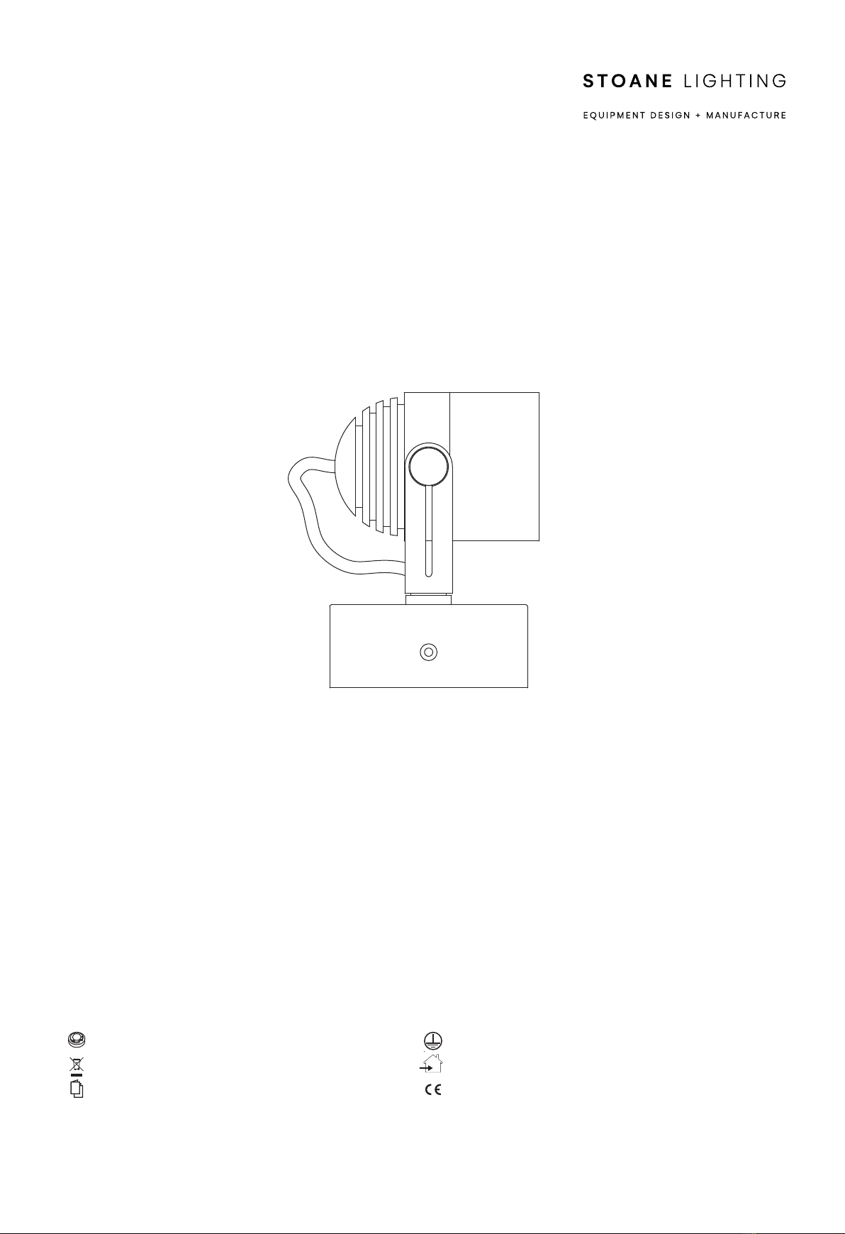
STX2.70 Integral
Installation and Maintenance
Instructions
IMPORTANT: All wiring connections must be made before switching on mains power.
European Conformity
Please retain these instructions for future reference
This product should not be disposed of in your general waste
Class I - Fitting must be Earthed
Indoor Use Only
Xicato XIM LED Module
STX2.70 Integral.pdf 1 16/04/2020 09:22:13

Electrical Supply
Installation must be carried out by a qualified electrician in
accordance with BS 7671:2008 Wiring Regulations.
230/240V AC 50/60Hz mains supply.
Site conditions: LED equipment is more susceptible to
static damage and overvoltage than previous technology.
Before handling or connecting to the mains supply ensure
that all MSL products are protected from static discharge
and that the mains supply is to regulation. (230V +10
-6%)
This fitting is supplied with a Xicato LED module. Refer to
the fitting label for the module version and wattage. More
information on the module can be found at
www.xicato.com/support
Mains cables must be double insulated, strain relieved
and separated from E.L.V output cables.
All connections must be made before switching on mains.
The light source contained in this luminaire shall only be
replaced by the manufacturer or his service agent or a
similar qualified person.
All lighting equipment is delicate and easily damaged
through misuse or inappropriate installation (mechanical
or electrical). Repairs and replacements may cause
delays and will be chargeable. Contact MSL for support if
required. For full warranty terms & conditions please visit
our website.
Dimming control circuit source must be of SELV insulation
class.
This fitting can be suitable for DALI, 1-10V, on board or
Bluetooth dimming. Please check the product label for
the dimming protocol of the supplied fitting.
Installation
Check that the mounting surface is suitable for the
installation of this fitting.
A suitable hole is required for incoming mains supply.
Step 1 Secure the mounting bracket to the mounting
surface with suitable fixings.
Step 2 Make Live and Neutral connections to the
SELV LED PSU and the Earth connection to
the supplied connectors. Punch holes through
the rubber inserts as required.
Additional dimming connections (if specified)
will be marked for easy identification.
Dim (+) purple
Dim (-) grey
Step 3 Attach the body of the fitting to the mount
bracket and secure with the supplied M4
fixings. Ensure these fixings are fully
tightened. Take care not to trap any cables
when securing in place.
WARNING: Do not look at exposed LED lamps in
operation. Eye injury can result.
Cleaning:
Fully isolate the fitting and allow to cool.
Clean the fitting with a damp lint free cloth from a mild
solution of soap and water. The fitting must be
completely dry before reconnecting power.
Incompatible or abrasive chemicals can damage the
fitting, contact MSL for advice if required.
Bluetooth Low Energy (If applicable)
BLE networks should be secured during
commissioning via the Xicato Control Panel software.
This fitting can be dimmed via Bluetooth using the
Ximtroller app available from the Apple App Store.
STX2.70 Integral.pdf 2 16/04/2020 09:22:13

MIKE STOANE LIGHTING | EQUIPMENT DESIGN + MANUFACTURE
1 2
3
Additional connectors will
be available for dimming
connections (if specified).
Suitable connectors are
supplied for loop in/out of
mains.
Connect Earth
LN
E
Mains connections from PSU
White = Neutral
Black - Live
STX2.70 Integral.pdf 3 16/04/2020 09:22:13
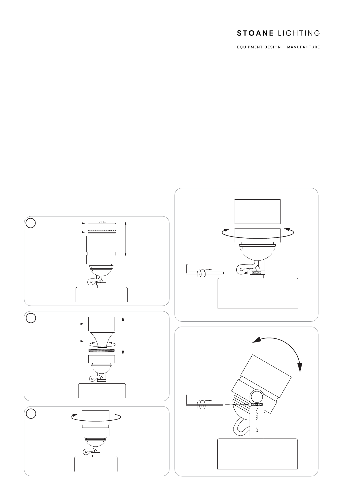
Reflector
Bezel
1
2
3
Pan
Tilt
Accessories
Circlip
MODULE AND ACCESSORIES
The fitting uses a Xicato XIM LED module. The colour
temperature and lumen output can be found on the
product label on the fitting.
To add/remove accessories:
Isolate the fitting from the supply and allow to cool.
Step 1 To replace accessories remove circlip and load
accessories. Reattach circlip to secure.
Step 2 To replace optic/reflector unscrew bezel in an
anti clockwise direction.
Step 3 Remove old optic/reflector and fit new reflector.
Refit the bezel by screwing on in a clockwise
direction.
Note that the 9mm XIM uses an optic, while the 19mm
XIM modules use screw in reflectors. These are not
interchangable.
ADJUSTMENT
To adjust the tilt and pan of the fitting use the supplied
2.5mm Allen key to loosen off the tilt and pan lock screws.
Once the desired angle is achieved lock off the screws.
DO NOT over tighten the screws as this could damage
the lock and cause it to no longer function.
STX2.70 Integral.pdf 4 16/04/2020 09:22:13
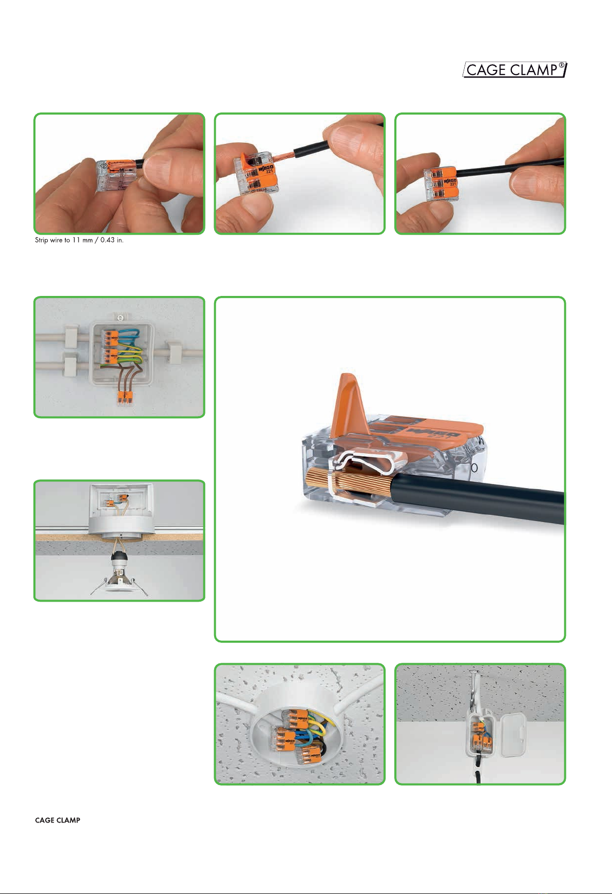
Lighting distribution in ceiling canopy
Then lower lever to close the clamp.
COMPACT Splicing Connectors for All Conductor Types
221 Series
– Description and Handling –
* For aluminum conductors, see notes in Section 14.
fine-stranded,
tip-bondedstranded
fine-stranded,
also with tinned
single strands
®
clamps the following
copper conductors:*
solid
Pendant light connection in suspended ceilings
Wiring fine-stranded conductors in a junction box.
Individual design of low-voltage lighting systems.
Termination: Open clamping unit using the lever and
insert conductor.
STX2.70 Integral.pdf 5 16/04/2020 09:22:13

29,9
8,3
18,6
13,1
8,3
18,6
18,7
8,3
18,6
IN32 A
450 V/4 kV/2
0.14 -
0.2 -
Pack.
Unit
Item No.
COMPACT splicing connector for all conductor
types, 3-conductor connector, with operating levers,
Pack.
Unit
Item No.
COMPACT splicing connector for all conductor
types, 5-conductor connector, with operating levers,
IN32 A
450 V/4 kV/2
0.14 -
0.2 -
Pack.
Unit
Item No.
COMPACT splicing connector for all conductor
types, 2-conductor connector, with operating levers,
COMPACT Splicing Connectors for All Conductor Types
221 Series
2Strip length, see packaging or instructions.
1in grounded power lines
450 V rated voltage
4 kV rated surge voltage
2pollution degree
(also see Section 14)
COMPACT splicing connectors
Tool-free connection of up to 5 stripped fine-stranded con-
This is how it works:
Open the clamping point using one of the orange operat-
ing levers until the lever is in vertical position. The conduc-
tor can now be inserted, then the lever can be returned to
its rest position, flush with the connector housing.
The safety:
The specially designed rest position of the lever reliably
prevents accidental unclamping of a connected conductor.
Application safety, for any type of conductor (solid, strand-
ed, fine-stranded), is confirmed by approvals like ENEC
and UL.
AWG 24 - 12 AWG 24 - 12
LL
221-413
221-415
221-412
1
2
1
2
(10x50)500(10x100)1000
(10x25)250
STX2.70 Integral.pdf 6 16/04/2020 09:22:13
Table of contents
Other Stoane Lighting Spotlight manuals


Popular Spotlight manuals by other brands


Martin
Martin Mania SCX600 user manual

Viewpoint
Viewpoint 20004 owner's manual

LIVARNO home
LIVARNO home 375304 2101 Operating and safety information

Coemar
Coemar Panorama LED RGB instruction manual

Simon
Simon IL416109 quick start guide

Silicon Solar
Silicon Solar PatioPal-GS-SpotLight-36 operating instructions