Stober ComTrac User manual


STOBER Drives Inc. • ComTrac2012 • www.stober.com 1
Table of Contents
ComTrac Adjustable Speed Drives
Advantages and Features...................................................2
Performance........................................................................3
Washdown Duty ..................................................................4
Operating Characteristics....................................................5
Ratings and Dimension
.50 HP .......................................................................6
.75 HP .......................................................................7
1.0 HP .......................................................................8
1.5 HP .......................................................................9
2.0 HP .....................................................................10
3.0 HP .....................................................................11
5.0 HP .....................................................................12
Electric Remote Control (ERC) .........................................13
Selection and Performance Characteristics......................14
Installation Instructions......................................................16
Maintenance and Lubrication............................................18
"C" Series MGS Adjustable Speed Drives
Performance Specifications...............................................19
Ratings..............................................................................20
Dimensions........................................................................34
Mounting Positions............................................................70
"F" Series MGS Adjustable Speed Drives
Performance Specifications...............................................37
Ratings..............................................................................38
Dimension .........................................................................44
Mounting Positions............................................................70
"K" Series MGS Adjustable Speed Drives
Performance Specifications...............................................47
Ratings..............................................................................48
Dimensions........................................................................64
Mounting Positions............................................................71
Mounting Hollow Output Units...........................................68
Mounting Positions............................................................69
Terms and Conditions........................................................72
Company Profile
STÖBER was first established in Germany in 1934, and has been
a pioneer in the gearing industry ever since. Through constant
innovation, STÖBER today is known for high precision, high ef-
ficiency and low noise in their various gearing technologies. STO-
BER®Drives Inc., located in Maysville, KY, manufactures products
to serve the North American market.
Beginning with the ComTrac®Mechanical Variable Speed Reduc-
ers, STÖBER established itself as a technology leader, later
adding the innovative MGS®Modular Gear System to the product
offering. MGS®Food and Beverage Reducers excel in the harsh-
est of washdown environments.
STÖBER next introduced ServoFit®Precision Planetary Gear-
heads, establishing the standard for low noise and low back-
lash in the servo industry. The recent introduction of the SMS®
ServoFit Modular System gearheads adds a high precision, cost
effective alternative to the servo market.
STÖBER has the broadest offering of speed reducers available,
providing one stop shopping for both the industrial market and the
rapidly growing motion control market.
On behalf of the worldwide family of STÖBER employees, we
thank you for trying our products and pledge to continue to meet
your product and service needs with the newest solutions.
Sincerely,
Bernd Stöber, Chairman
Stöber Antriebstechnik GmbH
Peter Feil, VP/General Manager
STOBER Drives, Inc.
ComTrac®Adjustable Speed Drives

2STOBER Drives Inc. • ComTrac2012 • www.stober.com
Advantages:
You're probably already aware of the many common-sense
advantages offered by traction-type adjustable speed drives like
the ComTrac drive. When compared to mechanical belt-type, or
electrical adjustable speed drives, traction type drives offer:
• Often, a lower initial cost.
• Few worries about motor overheating during low speed
operation.
• No motor brushes to replace.
• Very compact and lightweight when compared to other me-
chanical drives.
• Simple design with few rotating components to wear or re-
place.
• Easily serviced by semiskilled personnel
• Low maintenance – doesn't need to be cycled through its
speed range to prevent component damage.
• 2 year warranty–your assurance of satisfactory product perfor-
mance.
Features:
Drive cone – The drive cone is made from ductile iron and is
precision ground for long service life. It contains inner air cham-
bers for efficient heat dissipation. It is independently supported by
a shielded bearing mounted into the motor adapter/slide – not just
by the motor bearing.
Traction ring – ComTrac's self-lubrication traction ring is made
from a proprietary material that provides exceptional resistance
to wear and high temperatures. When replacement is necessary,
only the ring and not the entire friction ring mounting flange is
replaced.
Speed adjustment – ComTrac's rack and pinion speed adjust-
ment system features stainless steel components to resist cor-
rosion and is dust resistant by design. The stainless steel pinion
shaft and ductile iron rack are designed to provide assured speed
adjustments in the wettest, dirtiest environments.
Handwheel control – Handwheel control with a position indicator
is standard on every ComTrac drive. Remote speed controls and
overspeed protection is also available.
All ComTrac drives are shipped with the handwheel positioned
on the left as viewed from the output shaft end of the drive. The
handwheel can be quickly and easily moved to the right side by
using the tools and instructions included with the drive.
Mounting position – ComTrac drives can be mounted in virtually
any position.
NEMA C-face input – All ComTrac drives feature a NEMA C-
face input – that means standard off-the-shelf motors, available
locally. ComTrac's patented corrosion resistant collet clamp ring
makes motor shaft attachment fast and simple. The proper hex
wrenches are included with each unit in the motor access cover.
When the motor must be replaced, it can be done easily and
quickly without disassembly of the entire drive.
In addition, the 0F unit is standard with a NEMA C-face output
flange. It enables you to add adjustable speed capability to new or
existing applications.
Torque compensator – The torque compensator assembly fea-
tures high-capacity cylindrical roller bearings – not needle bear-
ings – for long life and quiet operation. The design allows speed
changes during operation or while the drive is at rest. The load
compensating cams precisely match the pressure between the
drive cone and the traction ring in proportion to the load torque.
Cast iron housing – High tensile strength cast iron housing for
long service life in demanding applications.
Stainless steel nameplate.
Two year warranty – Every ComTrac unit is backed by a two-
year warranty.
Delivery – ComTrac units are shipped in 3 days or less.
Selection:
In general, proper selection of a ComTrac drive is as easy as the
drive is to operate.
1. Establish the maximum horsepower required by the driven
machine at maximum speed.
2. Select the drive which meets or exceeds the maximum HP
rating of the driven machine at maximum speed.
Part No. Example:
TD47 0 F K182 W
Traction Drive Model/Size
0– Non-geared
F– Flange Mount
Input for NEMA Frame Size (182TC)
Washdown/Severe Duty (Option)
Speed Control Made Simple!
ComTrac®Adjustable Speed Drives
STOBER Drives Inc. • ComTrac2012 • www.stober.com 3
Performance Specifications:
• Horsepower ratings – from 1/2to 10
• Output speeds – available from 2180 to 311 RPM
• Speed range – 5:1 to 7:1
• Output torques – up to 496 in.lbs.
• NEMA frames – from 56C to 215TC
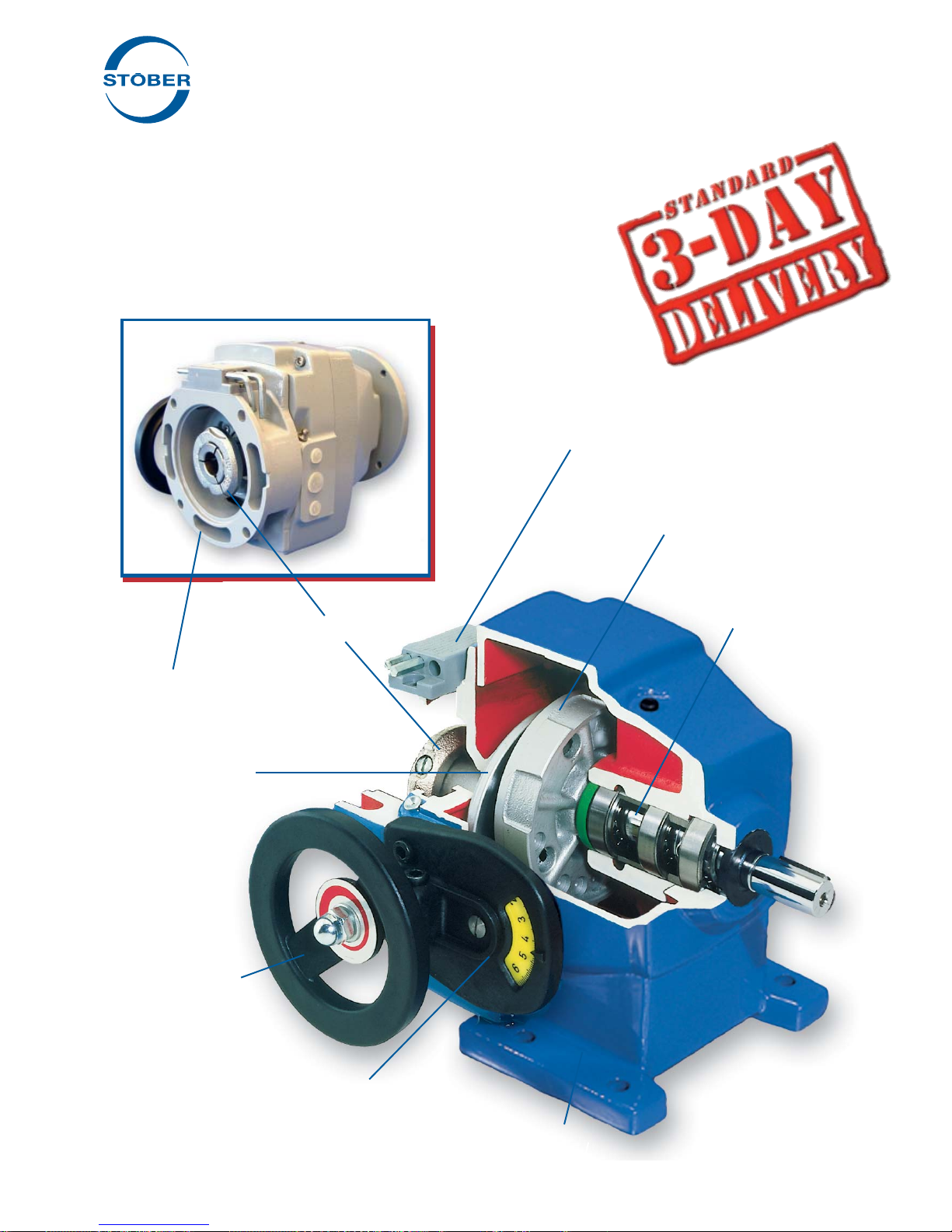
Torque Compensator
NEMA C-face Input
Drive Cone
Handwheel
Speed Adjustment Dial
Cast Iron Housing
Access Cover with wrenches
Collet Clamp Ring
Friction (Traction)
Ring Flange
Assembly
ComTrac®Adjustable Speed Drives
Footed unit shown for illustration only.
This style is no longer available.

4STOBER Drives Inc. • ComTrac2012 • www.stober.com
ComTrac®Adjustable Speed Drives
Washdown/Outdoor Service/ Severe Duty
Advantages:
STÖBER has developed a severe duty protection package for
ComTrac drives which significantly improves the drives' ability
to withstand the effects of outdoor use, exposure to excessively
humid or acidic environments, or spray washed with water or
caustic fluids.
The ComTrac severe duty package includes corrosion protection
for all functional components and housings including:
• Drive cone
• Motor clamping ring
• Motor slide and rack
• Bearing housing
• Main housing cover
To prevent corrosion, these components are protected by a spe-
cial heat treatment process similar to chrome plating.
Features:
Drive cone – Corrosion protected drive cone extends cone and
ring life.
Speed adjustment – The protected motor slide, stainless steel
control shaft with pinion, and greased rack and slideway assure
the proper speed adjustment.
NEMA C-face input – ComTrac's patented corrosion resistant
collet clamp ring assures ease of motor replacement.
External surface – All external surfaces are protected with a spe-
cial acid-resistant epoxy paint to prevent corrosion and lubricant
contamination.
Internal surface – All internal surfaces and bearing housing are
protected with a special anticorrosion paint.
Double seals – Double output seals can be provided for maxi-
mum protection in very harsh environments.
Mounting position – ComTrac drives in a vertical mounting posi-
tion (output shaft down) must be adapted to allow water to drain.
Stainless steel nameplate – Other features of the severe duty
unit are: stainless steel nameplate, rivets, and chrome plated
bolts.
Two year warranty – Like the standard drive, this ComTrac unit
is also backed by a two-year warranty.
Delivery – ComTrac units are shipped in 3 days or less.
Footed unit shown for illustration only.
This style is no longer available.
STOBER Drives Inc. • ComTrac2012 • www.stober.com 5
ComTrac®Adjustable Speed Drives
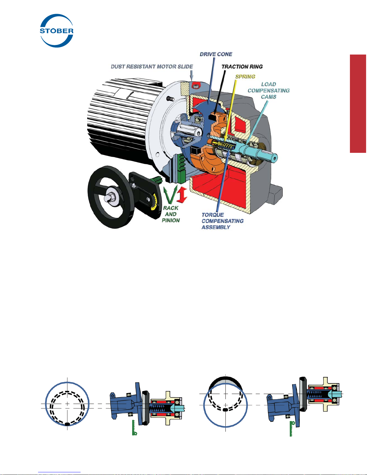
Operating Characteristics
Speed changes are made by changing the relative running
diameters of the drive cone and the traction ring. As the motor
and drive cone are moved upward, the contact point between the
cone and ring moves to the faster running outer diameter of the
drive cone and output speed increases. As the motor and drive
cone are lowered, the contact point between the cone and ring
moves to the slower running center of the drive cone and output
speed decreases.
Movement of the motor and drive cone are accomplished
through the use of a handwheel attached to a rack and pinion.
By turning the handwheel, the motor is easily raised or lowered
on the dust resistant motor slide. Speed changes can also be
made through the use of an optional electric remote control which
replaces the handwheel.
Speed Control Made Simple!
• Turn the handwheel – pinion moves the rack on the motor slide – up or down.
Maximum speed – motor slide up. Minimum speed – motor slide down.
Contact Point
Contact Point
Operation:
The ComTrac drive is an adjustable speed traction drive. Its
operation is based upon the transfer of power between the motor
mounted drive cone and the traction ring. The drive cone and
the traction ring are forced together to transmit torque through
the use of a spring loaded torque compensator assembly.
At rest, the spring inside the torque compensator produces only
a small contact pressure between the drive cone and traction
ring. Unlike other mechanical drives, the minimal spring pressure
allows speed changes to be made while the drive is at rest.
As the drive is started, the load compensating cams move
against each other to increase pressure between the drive cone
and traction ring. During operation, the load compensating
cams maintain the proper amount of pressure between the drive
cone and traction ring in proportion to the output load torque
required.
Footed unit shown for illustration only.
This style is no longer available.

6STOBER Drives Inc. • ComTrac2012 • www.stober.com
Motor Slide
Adjustment
All ratings shown are based on 1750 RPM motor speed and are rated to provide constant torque through the entire speed range. Contact STOBER for
constant horsepower applications. MOTOR MUST BE ORDERED SEPARATELY.
1) Speed tolerance at rated load is ±3%. At less than rated load, minimum speed may increase 5%.
2) The ComTrac drive operates at constant horsepower above transition values and at constant torque below transition values. Note shaded area.
Engineering advances may cause slight changes to the information shown.
Constant Horsepower Range Constant Torque Range
MAXIMUM TRANSITION
(2) MINIMUM
RPM (1) in.lbs. HP RPM (1) in.lbs. HP RPM (1) in.lbs. HP
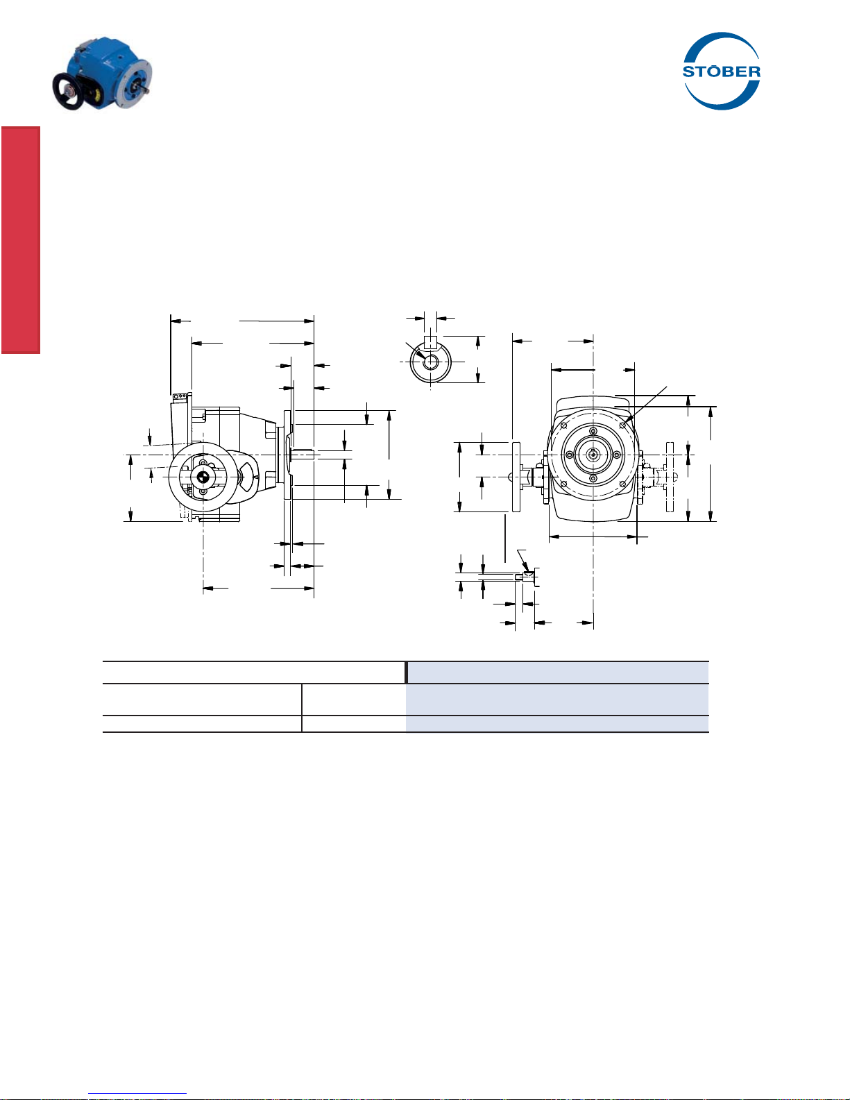
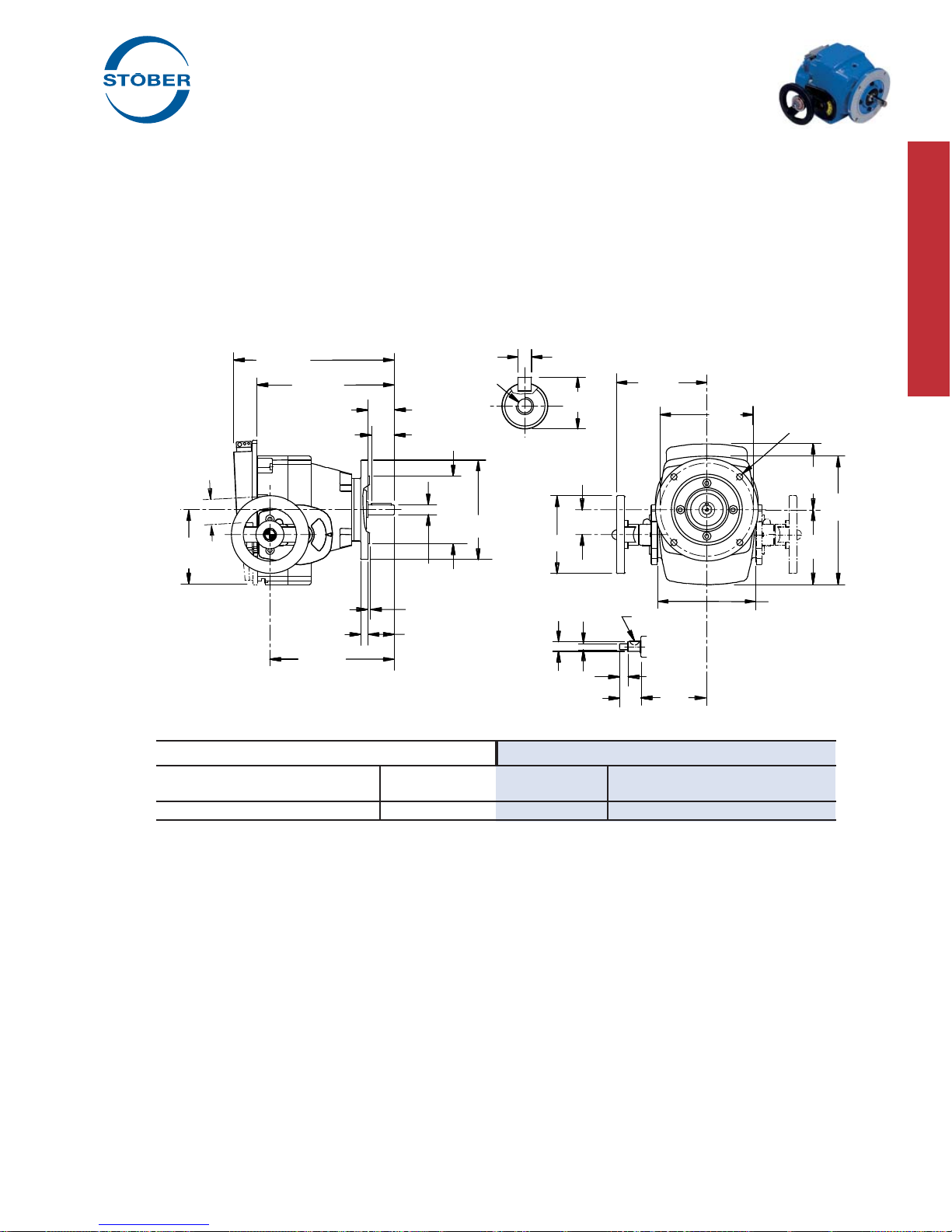
Part No. – 33 lbs.
TD270FK56
Flange Style
56C Input and Output
ComTrac®Adjustable Speed Drives
.50 HP @ 1750 RPM
All TD27 units are available with 56C and 143TC input.
10.67
8.86
1.87
4.41
4.72
8.07
.47
.625
+.0000
-.0005
4.500
+.000
-.001 6.50
2.06
.12
.1875 +.0000 / -.0005
x 1.38 Lg.
.71
#12-24 NC
1.57
4.92
M10
.5903
+.0000
-.0005 4.29
1.30
.51
5.875 3/8-16 NC
5.67
.20 x .26
1.65
6.22
8.11
Handwheel Shaft Dimensions
2.09
5.55
2,180 12.2 0.42 334 66 0.35 311 66 0.33

STOBER Drives Inc. • ComTrac2012 • www.stober.com 7
Motor Slide
Adjustment
All ratings shown are based on 1750 RPM motor speed and are rated to provide constant torque through the entire speed range. Contact STOBER for
constant horsepower applications. MOTOR MUST BE ORDERED SEPARATELY.
1) Speed tolerance at rated load is ±3%. At less than rated load, minimum speed may increase 5%.
2) The ComTrac drive operates at constant horsepower above transition values and at constant torque below transition values. Note shaded area.
Engineering advances may cause slight changes to the information shown.
Constant Horsepower Range Constant Torque Range
MAXIMUM TRANSITION
(2) MINIMUM
RPM (1) in.lbs. HP RPM (1) in.lbs. HP RPM (1) in.lbs. HP
ComTrac®Adjustable Speed Drives
.75 HP @ 1750 RPM
All TD27 units are available with 56C and 143TC input.
2,180 18.3 0.63 582 66 0.61 311 66 0.33
Part No. – 33 lbs.
TD270FK56
Flange Style
56C Input and Output
10.67
8.86
1.87
4.41
4.72
8.07
.47
.625
+.0000
-.0005
4.500
+.000
-.001 6.50
2.06
.12
.1875 +.0000 / -.0005
x 1.38 Lg.
.71
#12-24 NC
1.57
4.92
M10
.5903
+.0000
-.0005 4.29
1.30
.51
5.875
3/8-16 NC
5.67
.20 x .26
1.65
6.22
8.11
Handwheel Shaft Dimensions
2.09
5.55
8STOBER Drives Inc. • ComTrac2012 • www.stober.com
Motor Slide
Adjustment
All ratings shown are based on 1750 RPM motor speed and are rated to provide constant torque through the entire speed range. Contact STOBER for
constant horsepower applications. MOTOR MUST BE ORDERED SEPARATELY.
1) Speed tolerance at rated load is ±3%. At less than rated load, minimum speed may increase 5%.
2) The ComTrac drive operates at constant horsepower above transition values and at constant torque below transition values. Note shaded area.
Engineering advances may cause slight changes to the information shown.
Constant Horsepower Range Constant Torque Range
MAXIMUM TRANSITION
(2) MINIMUM
RPM (1) in.lbs. HP RPM (1) in.lbs. HP RPM (1) in.lbs. HP
ComTrac®Adjustable Speed Drives
1.0 HP @ 1750 RPM
All TD27 units are available with 56C and 143TC input.
Part No. – 33 lbs.
TD270FK143
Flange Style
143TC Input
56C Output
10.67
8.86
1.87
4.41
4.72
8.07
.47
.625
+.0000
-.0005
4.500
+.000
-.001 6.50
2.06
.12
.1875 +.0000 / -.0005
x 1.38 Lg.
.71
#12-24 NC
1.57
4.92
M10
.5903
+.0000
-.0005 4.29
1.30
.51
5.875 3/8-16 NC
5.67
.20 x .26
1.65
6.22
8.11
Handwheel Shaft Dimensions
2.09
5.55
2,180 24.4 0.84 821 66 0.86 311 66 0.33
STOBER Drives Inc. • ComTrac2012 • www.stober.com 9
Motor Slide
Adjustment
All ratings shown are based on 1750 RPM motor speed and are rated to provide constant torque through the entire speed range. Contact STOBER for
constant horsepower applications. MOTOR MUST BE ORDERED SEPARATELY.
1) Speed tolerance at rated load is ±3%. At less than rated load, minimum speed may increase 5%.
2) The ComTrac drive operates at constant horsepower above transition values and at constant torque below transition values. Note shaded area.
Engineering advances may cause slight changes to the information shown.
Constant Horsepower Range Constant Torque Range
MAXIMUM TRANSITION
(2) MINIMUM
RPM (1) in.lbs. HP RPM (1) in.lbs. HP RPM (1) in.lbs. HP
ComTrac®Adjustable Speed Drives
1.5 HP @ 1750 RPM
Part No. – 51 lbs.
TD370FK145
Flange Style
145TC Input
143TC Output
11.69
9.88
2.24
4.37
5.94
9.09
.47
.875
+.0000
-.0005
4.500
+.000
-.001 6.50
2.13
.12
.1875 +.0000 / -.0005
x 1.77 Lg.
.96
1/4-20 NC
2.05
4.92
M10
.5903
+.0000
-.0005 4.53
1.30
.51
5.875 3/8-16 NC
5.91
.20 x .26
1.97
6.69
9.72
Handwheel Shaft Dimensions
2.17
5.67
2,100 38 1.27 856 97 1.31 420 97 0.64

10 STOBER Drives Inc. • ComTrac2012 • www.stober.com
Motor Slide
Adjustment
All ratings shown are based on 1750 RPM motor speed and are rated to provide constant torque through the entire speed range. Contact STOBER for
constant horsepower applications. MOTOR MUST BE ORDERED SEPARATELY.
1) Speed tolerance at rated load is ±3%. At less than rated load, minimum speed may increase 5%.
2) The ComTrac drive operates at constant horsepower above transition values and at constant torque below transition values. Note shaded area.
Engineering advances may cause slight changes to the information shown.
Constant Horsepower Range Constant Torque Range
MAXIMUM TRANSITION
(2) MINIMUM
RPM (1) in.lbs. HP RPM (1) in.lbs. HP RPM (1) in.lbs. HP
ComTrac®Adjustable Speed Drives
2.0 HP @ 1750 RPM
2,100 51 1.70 1,162 97 1.79 420 97 0.65
Part No. – 51 lbs.
TD370FK145
Flange Style
145TC Input
143TC Output
11.69
9.88
2.24
4.37
5.94
9.09
.47
.875
+.0000
-.0005
4.500
+.000
-.001 6.50
2.13
.12
.1875 +.0000 / -.0005
x 1.77 Lg.
.96
1/4-20 NC
2.05
4.92
M10
.5903
+.0000
-.0005 4.531.30
.51
5.875 3/8-16 NC
5.91
.20 x .26
1.97
6.69
9.72
Handwheel Shaft Dimensions
2.17
5.67

STOBER Drives Inc. • ComTrac2012 • www.stober.com 11
Motor Slide
Adjustment
All ratings shown are based on 1750 RPM motor speed and are rated to provide constant torque through the entire speed range. Contact STOBER for
constant horsepower applications. MOTOR MUST BE ORDERED SEPARATELY.
1) Speed tolerance at rated load is ±3%. At less than rated load, minimum speed may increase 5%.
2) The ComTrac drive operates at constant horsepower above transition values and at constant torque below transition values. Note shaded area.
Engineering advances may cause slight changes to the information shown.
Constant Horsepower Range Constant Torque Range
MAXIMUM TRANSITION
(2) MINIMUM
RPM (1) in.lbs. HP RPM (1) in.lbs. HP RPM (1) in.lbs. HP
ComTrac®Adjustable Speed Drives
3.0 HP @ 1750 RPM
2,100 81 2.70 970 177 2.72 420 177 1.18
Part No. – 59 lbs.
TD470FK182
Flange Style
182TC Input
143TC Output
12.48
9.96
2.24
5.59
6.93
9.13
.47
.875
+.0000
-.0005
4.500
+.000
-.001 6.50
2.13
.12
.1875 +.0000 / -.0005
x 1.77 Lg.
.96
2.60
6.30
M10
.5903
+.0000
-.0005 5.241.30
.51
5.875
3/8-16 NC
6.81
.20 x .26
1.97
8.11
11.57
Handwheel Shaft Dimensions
2.80
7.20
1/4-20 NC

12 STOBER Drives Inc. • ComTrac2012 • www.stober.com
Motor Slide
Adjustment
All ratings shown are based on 1750 RPM motor speed and are rated to provide constant torque through the entire speed range. Contact STOBER for
constant horsepower applications. MOTOR MUST BE ORDERED SEPARATELY.
1) Speed tolerance at rated load is ±3%. At less than rated load, minimum speed may increase 5%.
2) The ComTrac drive operates at constant horsepower above transition values and at constant torque below transition values. Note shaded area.
Engineering advances may cause slight changes to the information shown.
Constant Horsepower Range Constant Torque Range
MAXIMUM TRANSITION
(2) MINIMUM
RPM (1) in.lbs. HP RPM (1) in.lbs. HP RPM (1) in.lbs. HP
ComTrac®Adjustable Speed Drives
5.0 HP @ 1750 RPM
2,100 137 4.56 1,102 266 4.65 420 266 1.77
Part No. – 88 lbs.
TD570FK184
Flange Style
184TC Input
182TC Output
15.98
13.39
2.75
6.30
8.11
12.32
.83
1.125
+.0000
-.0005
8.500
+.000
-.001 9.00
2.62
.26
.25 +.0000 / -.0005
x 2.20 Lg.
1.24
3/8-16 NC
3.35
7.87
M12
.7871
+.0000
-.0005 6.541.50
.59
7.250 1/2-13 NC
8.31
.20 x .30
2.40
9.61
13.43
Handwheel Shaft Dimensions
3.11
8.11

STOBER Drives Inc. • ComTrac2012 • www.stober.com 13
The STOBER Electric Remote Control (ERC) is a compact double
reduction gearmotor which is pinion mounted to the motor slide
track in place of the handwheel. A mechanical clutch within the
unit indicates the end of vertical motor travel in both directions by
making a clicking noise.
The ERC can be operated by push button or other type of control
(not included) to adjust the drive's speed. In many applications
it is advisable to use a limit switch with the ERC to prevent over-
speed or underspeed conditions.
Features:
• Speed changes can be made when the unit is stationary or
running.
• STOBER ERC can be quickly and easily added to existing
ComTrac drives without special tools.
• All STOBER ERC units are designed for washdown/severe
duty applications and are available from stock.
• Available voltages:
– 115V, single phase, 60 Hz
– 230/460V, three phase, 60 Hz
ComTrac®Adjustable Speed Drives
Electric Remote Control
Table No. 1 ERC – Dimensions (Inches)
ComTrac Model Number
Size Single Phase Three Phase A B C
TD27 ERC27-1 ERC27-2 6.18 7.09 9.72
TD37 ERC37-1 ERC37-3 6.14 7.05 9.68
TD47 ERC47-1 ERC47-3 7.12 8.03 10.67
TD57 ERC57-1 ERC57-3 7.56 9.06 11.10
Motor dimensions may vary slightly from values shown.
Reference point for handwheel center.
Motor Clearance
On some TD27 ComTrac units, the motor can be lower than the base of the unit when adjusted to the slowest setting. The following formula
will determine a value based on the length of the motor to be installed.
XX = .055 x B (When "B" = motor length)
XX
B
ERC for ComTrac sizes: TD57
1.85
9.96
2.72
BA
C2.28
2.09
4.92
ERC for ComTrac sizes: TD27, TD37, and TD47.
1.85
9.96 2.72
BA
C
2.28
2.09
4.92
Footed unit shown for illustration only.
This style is no longer available.

14 STOBER Drives Inc. • ComTrac2012 • www.stober.com
Selection:
The ComTrac drives shown in the selection tables are rated for
constant torque operation – where required horsepower varies di-
rectly in proportion to the speed of the driven machine. All ratings
shown are based upon standard NEMA C-face motor designs with
1750 RPM input speed. Contact STOBER technical support for
selection assistance for motor speeds other than 1750 RPM.
Basic selection procedure is as follows:
1. Establish the maximum horsepower required by the driven
machine at maximum speed.
If only the driven equipment's maximum torque (T) require-
ment is known, use the following formula to convert the torque
value to horsepower: T x RPM
HP =
63,025
2. Select the drive which meets or exceeds the maximum HP
rating of the driven machine at maximum speed.
Since the typical ComTrac application requires constant torque
over the entire speed range, there will be an adequate service
factor to protect the traction ring from damage.
Use the output speed ratings shown in the tables to select an out-
put speed which meets or exceeds the requirement of the driven
machine. Read across the table to determine if the drive's actual
minimum and maximum speed, torque, and horsepower ratings
meet the requirements of the driven equipment.
If the maximum output speed shown in the table is too low, go to
the next higher speed. Should the torque or horsepower ratings
shown be below the driven equipment's requirements, consult the
next higher horsepower rating in the selection data.
Motor Performance
The ratings shown in the ComTrac selection tables are based on
standard NEMA motors with the following specifications:
• 1750 RPM speed
• 60 Hz operation
Application Matched Options
Several options for ComTrac drives, such as remote controls, are
included in this catalog. In addition, the following options are also
available:
• 50 Hz operation for export
• Motor enclosures
For application and selection assistance for these options and
others, contact your local STOBER distributor.
Non-Standard Application Conditions
For constant horsepower applications, or any of the nonstandard
application conditions shown below, contact STOBER technical
support.
Unusual Loading Conditions:
• Heavy shock load
• High inertia load
• Load reversals or overhauling loads
• More than ten starts per hour
Unusual Environmental Conditions:
• High altitudes – above 5000 feet
• Corrosive chemicals
• Excessively dusty or abrasive environments
• Ambient temperatures below 25° F or above 125° F
Nonstandard Motors:
• Motor frame sizes other than those shown in the tables
Nonstandard Mounting:
• Output shaft up or down (V5 or V6 mounting)
Not Recommended for Mounting:
• Explosive environment of any type
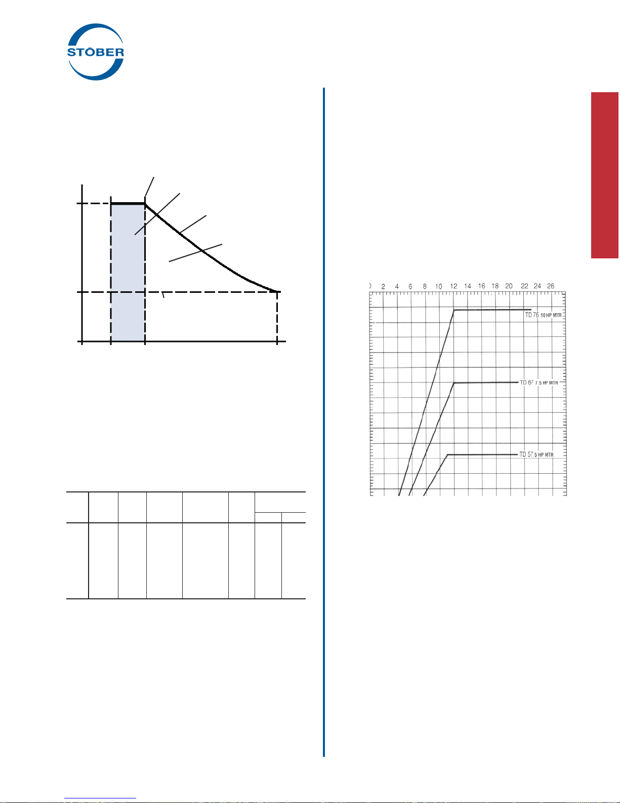
Performance Characteristics
Because of its mechanical operation, the ComTrac drive gener-
ally produces constant output torque. While the induction motor
produces constant horsepower and constant speed, the two are
combined in a manner that provides optimum utility and economy.
As the ComTrac Performance Chart shows, the drive has two
operating regions.
1. Constant torque between the drive's absolute minimum
speed and transition speed.
2. Constant horsepower between the transition speed and
maximum speed.
When selecting a ComTrac drive, it is important to choose a unit
which will not allow the cone and ring system to be over powered
by the motor. As shown in the ComTrac Performance Chart, Com-
Trac drives should always be selected so that the output torque
required is well below the torque capability of the cone and the
ring system.
ComTrac®Adjustable Speed Drives
Selection and Performance Characteristics
STOBER Drives Inc. • ComTrac2012 • www.stober.com 15
TRANSITION SPEED
Output Torque (in.lbs.)
Min. Trans. Max.
Output Speed (RPM)
Torque Capacity of the Cone/Ring System
Constant Torque Operating Range
Constant Motor Output HP
Constant HP Operating
Range
Torque Rating at Maxi-
mum Speed
ComTrac®Adjustable Speed Drives
Selection and Performance Characteristics
Table No. 1
ComTrac Series 0F Specifications
Output C-Face Output Speed
Motor NEMA Torque Model Output Speed Range (RPM)
HP Frame in.lbs. Number Flange Range Max. Min.
.50 56C 16 TD270F 56C 7:1 2180 311
.75 56C 24 TD270F 56C 7:1 2180 311
1.00 143TC 32 TD270F 56C 7:1 2180 311
1.50 145TC 48 TD370F 143/145TC 5:1 2100 420
2.00 145TC 64 TD370F 143/145TC 5:1 2100 420
3.00 182TC 99 TD470F 143/145TC 5:1 2100 420
5.00 184TC 168 TD570F 182/184TC 5:1 2100 420
Minimum output torque rating based on 1750 RPM maximum input
speed.
0 2 4 6 8 10 12 14 16 18 20 22 24 26
Output Speed (RPM x 10)
Output Horsepower (HP) Rating
Graph No. 2 ComTrac Series 0F Output HP
TD57, 5 HP motor
TD47, 3 HP motor
TD37, 2 HP motor
TD37, 1.5 HP motor
TD27, 1.0 HP motor
TD27, .5 HP motor
TD27 .75 HP motor
7
6
5
4
3
2
1
Graph No. 1 ComTrac Performance Chart
Overhung Loads

16 STOBER Drives Inc. • ComTrac2012 • www.stober.com
Step 4 – Through the access hole, tighten the hex socket screw
on the motor clamp hub to the tightening torque shown in the table
below. The correct size hex wrench is
provided. DO NOT OVERTIGHTEN.
SHOWN WITHOUT MOTOR FOR
DEMONSTRATION.
Table No. 1
Clamp Ring Setscrew Tightening Torque
ComTrac Size in. lbs.
TD27 88.5
TD37 88.5
TD47 221
TD57 434
Step 5 – Reattach access cover.
When couplings, gears, sprockets or pulleys are mounted on the
output shaft, be sure to mount them as close as possible to the
housing to minimize the effects of overhung loads on shafts and
bearings.
CAUTION: Do not drive couplings, sprockets, gears or pulleys
onto the output shaft with hard hammer blows, since damage to
internal gears or bearings will result. All output shafts have a met-
ric centering thread for attachment of transmission devices. They
can be pulled on gently with a bolt and plate.
ComTrac®Adjustable Speed Drives
Installation Instructions
ComTrac Series 0F
Units with C-face input and output are de-
signed to attach to any speed reducer with
a NEMA C-face input. Care must be taken
to follow the speed reducer manufacturer's
recommended mounting instructions.
NOTE: ComTrac Series 0F drives do not
have mounting feet. The drive and motor assembly is mounted on
the speed reducer which must support the reducer, ComTrac, and
the motor. If there is concern for the ability of the reducer mount-
ing feet to support the entire assembly, a larger speed reducer
may be required.
The output shaft of the ComTrac drive is shipped from the factory
with a protective coating. Remove this coating with a suitable
nonflammable solvent. Precaution must be taken not to allow the
solvent to contact the output shaft oil seal, since damage to the
seal may occur.
Motor Installation
Step 1 – Remove the access cover.
Step 2 –Lubricateandinsertkeyed motor shaft into the slottedbore
of the drive cone shaft.
NOTE: For ease of installation, secure the key to the motor shaft.
(Staking near the end of the keyway or a temporary adhesive
works well.)
Step 3 – Tighten the four motor flange bolts.
IMPORTANT: Jog the motor several revolutions before
tightening the motor clamp to assure proper position of the
drive cone on the motor shaft. See Page 5 for illustration.
STOBER Drives Inc. • ComTrac2012 • www.stober.com 17
ComTrac®Adjustable Speed Drives
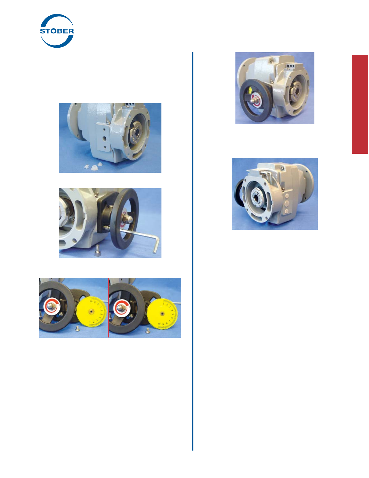
Installation Instructions
Handwheel Position
ComTrac drives are furnished with the speed control handwheel
on the left, as viewed from the output shaft end of the drive. If it is
necessary that the handwheel be moved to the opposite side, this
can be accomplished very easily with the hex wrenches provided
with each drive.
Procedure for Changing Handwheel Position:
Step 1 – Remove the three (3) plastic plugs in the housing on the
side opposite the handwheel.
Step 2 – Remove the handwheel and indicator assembly by remov-
ingthetwo(2)socket-headcapscrews which secure the handwheel
indicator assembly to the housing.
Step 3 – Turn the yellow numbered position indicator wheel around
byremovingtheslottedscrew.(Besuretoremovethetapecovering
to expose position numbers on the other side of the wheel.)
Step 4 – Replace the slotted screw.
Step5–Placepinion,handwheelandindicatorondesiredsideofthe
drive's housing (from where the three plastic plugs were removed),
andsecurewiththetwosocket-headcapscrewsremovedpreviously.
Step6–Relocatetheplasticplugstotheholeswherethehandwheel
was originally mounted.
Lubricate the motor slide and rack (both sides) with one (1) stroke
with a grease gun through the fittings provided in the housing.
IMPORTANT: Do not over lubricate the motor slide. Under nor-
mal conditions, maintenance of the motor slide and rack should
only be required one time per year.
Electric Remote Control (ERC) Installation
The Electric Remote Control consists of a small gearmotor
mounted on the ComTrac drive in place of the manual handwheel
control.
Procedure
Attaching the ERC is accomplished by simply removing the two
(2) socket-head capscrews that secure the handwheel and indica-
tor assembly to the drive's housing.
Replace the handwheel/indicator assembly with the ERC and
secure it to the housing with the same two screws.
Lubricate the motor slide and rack (both sides) with one (1) stroke
with a grease gun through fittings in the housing.
The ERC is operated by pushbutton or other form of contact
(furnished by customer). A mechanical clutch is contained within
the gearmotor which indicates the end position of travel, in either
direction, by making a clicking noise. Also, the ERC can be oper-
ated while the drive is stationary.
Power required for the ERC is 230 volt, 3 phase, 60 hertz, or 115
volt, single phase, 60 hertz.
The wiring diagram for the ERC is inside the motor's conduit box.
The ERC motor and drive should be protected from excessive
dust, flying chips, and oil splashes.

18 STOBER Drives Inc. • ComTrac2012 • www.stober.com
Maintenance and Lubrication
WARNING: Before beginning any work on the ComTrac drive
system, disconnect the power source (lock-out the motor
starter, and unload breakers, backstops, etc.). Failure to
do so may cause serious personal injury and/or machinery
damage.
Series 0F
These units require lubricant only in the cam and bearing
chamber and are shipped with the lubricant in them. There is a
sufficient quantity of lubricant to allow mounting the non-geared
ComTrac Drive in any position.
Table No. 1
Series "0" – Bearing and Cam Chamber Oil Quantity
ComTrac Size fluid oz.
TD27-0 1.5
TD37-0 1.7
TD47-0 1.9
TD57-0 4.4
For normal indoor installations the handwheel or ERC control pin-
ion and motor slide rack should be lubricated through the grease
fitting every six months using NLGI No. 2 grease. One stroke of
a grease gun is sufficient. When the drive is operating under wet
conditions, increase the frequency of lubrication to once a month.
Under normal operating conditions the synthetic oil in the cam
and bearing chamber does not need to be replaced. If for any
reason some quantity of lubricant is lost, remove the rest of the
lubricant from the cam and bearing chamber and replace it with
the type and quantity of oil listed in the lubrication table shown.
Table No. 2 Bearing and Cam Oil Manufacturers
Lubricant
Manufacturer AGMA Lubricant ( No. 5EP)
Darmex 9140
Exxon Spartan 220
Mobil * Mobilgear 630
Gulf HD220
Keystone KSL-366
Lubriplate APG90
* Mobile SHC626 is used for the initial fill. If refill is necessary, any of
the above products may be used.
For installations in the food, dairy, beverage and baking indus-
tries, where special lubricants are required, a suitable grease of
the user's preference should be used.
When a ComTrac Drive with C-face output (Series 0F) is attached
to a speed reducer, follow the manufacturer's lubrication instruc-
tions for the reducer mounting before start-up.
ComTrac®Adjustable Speed Drives
Maintenance and Lubrication Instructions
In order to obtain long life and trouble-free operation from your
ComTrac®drive, it is essential that proper installation and operat-
ing procedures be followed.
The torque required by the application must not exceed the
reducer torque capacity shown on the nameplate. For safety pur-
poses a safety coupling should be installed between the reducer
and the driven load. Otherwise, overload may cause damage to
the interior parts of the reducer which may result in breaking the
reducer housing. As a result, persons could be injured by flying
parts or splashing hot gear oil.
This catalog includes basic directions for mounting and start-up of
the ComTrac®drive, as well as lubrication information. Failure to
follow these instructions will void the drive's warranty.
If you have questions about the installation, operation or mainte-
nance of your ComTrac®drive, please contact your local STOBER
distributor for assistance.
WARNING:
Safety is the most important consideration when operating any
type of drive. Through proper application, safe handling methods,
and wearing appropriate clothing, you can prevent accidents and
injury to yourself and fellow workers.
The shafts of ComTrac®drives rotate at very high speeds and
can cut off or severely injure hands,
fingers, and arms. Use appropriate
guards for shafts and other rotating
parts at all times. Follow all directions
in the service instruction manual.
Obey all federal, state and local safety
regulations when operating the drive.
• Always be sure electrical power is off while making electrical
connections and during installation and maintenance of the
unit.
• Keep clothing, hands, and tools away from ventilation open-
ings on motors and from all rotating parts during operation.
• Lift drive with a double rope sling or other proper lifting
equipment of adequate strength. Make sure load is secured
and balanced to prevent shifting when unit is being moved.
Lifting heavy drives by hand may be dangerous and should be
avoided.
• The intended use of lifting lugs is to handle the weight of the
unit only. Never use a lifting lug to lift attached assemblies.
• Never operate drive at speeds higher than those shown on
the nameplate, or personal injury may result. Contact STO-
BER Drives Inc., if there is any change of operating conditions
from those for which the unit was originally sold (as stamped
on the nameplate). Failure to comply could result in personal
injury and or machinery damage.
• Always follow good safety practices at all times.
Each drive is tested before delivery. Before installation, however,
it is advisable to examine the unit for possible damage which
might have occurred during transit. If damage is discovered, it
should be immediately reported to the transport agent.
If installation is delayed after receipt of the MGS speed reducer,
the drive should be stored in a clean, dry place until put into ser-
vice. Long term storage requires special procedures. If not kept
in a heated, dry area, consult STOBER Drives, Inc. for storage
instructions.
NOTE: If it is necessary to clean drive shafts, take care to protect
the oil seals.
IMPORTANT: Do not use any device to hammer the unit onto the
output shaft during installation since the bearing races could be
damaged.
WARNING
Cover rotating
parts with safety
guard before
turning on
power.
Table of contents
Other Stober Inverter manuals

Stober
Stober MDS 5000 User manual

Stober
Stober POSIDYN SDS 5000 User manual

Stober
Stober POSYDYN SDS 4281 Operator's manual

Stober
Stober POSIDRIVE FDS 5000 series User manual

Stober
Stober POSIDRIVE FDS 5000 series User manual

Stober
Stober POSITool MDS 5000 User manual

Stober
Stober POSIDRIVE MDS 5000 User manual

Stober
Stober POSIDRIVE MDS 5000 User manual


