AZZURRO ZCS 3-6-ZSS-HP User manual

QUICK INSTALLATION GUIDE
HYBRID INVERTER 3-6-ZSS-HP
Rev. 1.0 – 23/05/2022

Note: If the hybrid inverter is to be installed under different conditions from those shown in the diagrams
above, contact technical support to check whether it is feasible.
1. INSTALLATION
Maximum inclination
permitted: 15°
Correct installation in
vertical position
Maximum height from ground permitted: 180 cm
2. WIRING DIAGRAM FOR HYBRID STORAGE INVERTER
1. INSTALLATION AND DISTANCES
20 20
Distances for installations of a single inverter
Distances for installations of multiple inverters
Always wear protective
clothing and/or personal
protective equipment
Always consult the
manual
General notice -
Important Safety
Instructions
Panels
Hybrid Inverter
Meter
Critical Loads Utilities
Batteries

1
5
6
7
2 3 4
9
810
11
12
13
1. Menu/Back
2. Up
3. Down
4. Enter/Forward
5. Discharge status
6. Charge status
7. Alarm status
8. System status
9. PV production
10. Grid power
11. Home
consumption
12. Battery power
13. Date and time
14. Wi-Fi signal
14
3. LIGHTS AND BUTTONS
Main menu
1. System settings
2. Advanced settings
3. Event list
4. System Info
5. Software Update
6. Energy statistics
From the main menu, press
“Menu/Back” to enter the main
menu.
The main menu contains five
different sections:
4. MAIN MENU
1. System settings
1. Language Setting
2. Time
3. Safety Param.
4. Energy Storage Mode
5. Autotest
6. PV input mode
7. EPS Mode
8. Select.Commun.Address
2. Advanced settings
1. Battery parameters
2. Anti Reflux
3. IV Curve Scan
4. Logic interface
5. Factory Reset
6. Parallel setting
7. Rest Buetooth
8. CT Calibration
9. Battery Active
10. Set Electricity Meter
3. Event list
1. List of current events
2. List of historical events
4. System Info
1. Inverter Info
2. Battery Info
3. Safety parameters
6.Energy Statistics
Today Week Month Year Life Cycle
PV prod. PV prod. PV prod. PV prod. PV prod.
AutoCon AutoCon AutoCon AutoCon AutoCon
Export Export Export Export Export
Consumption Consumption Consumption Consumption Consumption
AutoCon AutoCon AutoCon AutoCon AutoCon
Amount Amount Amount Amount Amount
5. SW Update
Start Update ...
PWD: 0715
PWD: 0715
Status of the HYD-ES
inverter
On Grid
Green light
Off-Grid
Green light
Alarm
Red light
On-grid On
Standby (On-Grid) Intermittent
Off-Grid On
Standby (Off-Grid) Intermittent
Alarm On
Charge

The Inverter will remain in Standby until:
•the difference between the PV production and the
power required by the loads is less than 100W
•the battery is fully charged and the PV production
is higher than the consumption (with tolerance of
100W)
•the battery is flat and the PV production is lower
than the consumption (with tolerance of 100W)
Press the “↓” key once from the main menu to access the instantaneous
information on the battery and AC grid.
Press the “↑” key once from the main menu to access the
instantaneous information on the DC side of the inverter.
6. OPERATING STATES IN SELF USE
5. QUICK INFO ON SYSTEM STATUS
When the power produced from the photovoltaic
system is greater than the power required by the
loads, the Inverter inverter will charge the battery
with the excess energy.
When the battery is fully charged, or when the
charging power is limited (to preserve the integrity of
the battery), the excess energy will be exported to
the grid.
Charge
When the power of the photovoltaic system is less
than the power required by the loads, the system will
use the energy stored in the battery to supply the
domestic utilities.
Discharge
When the sum of the power produced by the
photovoltaic system and supplied by the battery is
less than that required by the loads, the extra
energy will be taken from the grid.
Standby
Standby
Standby
Charge
Charge
Discharge
Discharge

3.1 Connessione Batteria
If the system has to be switched off, make sure to disconnect the AC voltage first by
opening the dedicated switch.
NEVER turn off the batteries before disconnecting the AC voltage, therefore with the
storage system connected to the AC grid.
Note: Maximum DoD
Programmable 80%
8.1 SINGLE PYLONTECH BATTERY
7. BATTERY CONNECTION
3.3 Connessioni alla Rete
Inverter
PIN
Battery
communication Note
1 CAN H (blue wire) Communication between
battery BMS and Inverter
2CAN L white/blue
wire )
Inverter COM connector
Fase 2 Fase 3
Power
Connections
Communication connections
In case of a single battery, two power cables (positive and negative) and a communication cable shall be connected.
This connection is shown in the figures below:
Note: The communication cable is located inside the
kit in the inverter box.
Note: The DIP switch positions must be set according to the
factory settings
The communication
cable shall be
connected to the
battery's CAN port

When connecting multiple batteries in parallel, connect the communication cable between the inverter's CAN port
and the CAN port of one of the batteries. This battery will be referred to as the MASTER.
A communication cable will go from the link port 1 of the MASTER battery to the Link port 0 of the second battery
called SLAVE 1.
In case of additional batteries, the communication cable will be connected as indicated above for the connection of
the MASTER battery to SLAVE 1.
The last battery will only
have the port 0 link connected.
8.2 PYLONTECH BATTERIES IN PARALLEL
8.3 SINGLE 4K4 WECO BATTERY
Master
Slave 1
Slave n
…
The batteries must be connected in a “loop” as shown in the side
photo, and explained below:
Positive and Negative power cables shall be connected one to the
first battery ( MASTER) and the other to the last battery
(SLAVE N).
Inverter
negative
Inverter
positive
3.1 Connessione Batteria
Note: To connect multiple batteries in parallel, use the appropriate cables (power and
connection) contained in the kit.
Note: The DIP switch positions must be set according to the
factory settings
Note: The communication cable
between battery and inverter is
inside the inverter box
Note: Maximum DoD programmable 90%
Inverter
PIN Battery communication Note
1 CAN (blue wire) Communication between
battery BMS and Inverter
2 CAN (white -blue wire)
Inverter COM connector

In case of SINGle BATTERY:
1. Connect the BMS-CAN
2. Set the DIP switch as in the
pictures.
3. Connect the power cable to
the terminal B+ and B- (as
shown in the picture)
4. Connect the PE wire to the
battery .
In case of multiple batteries connected in parallel or when adding new batteries to a system with batteries already
installed and working, make sure that the difference between the voltages of all the batteries is less than 1.5 Volt.
Each battery must be measured individually, therefore make sure the batteries are not connected to each other.
(If the value is higher than 1.5 Volt, contact Technical Support)
Note: Turn off the batteries each time the position of the
DIP switches changes.
To access the battery connection, remove the cover by unscrewing the crosshead screws.
In the event of MULTIPLE BATTERIES, connect the communication cable from the CAN port of the inverter to the
CAN-BMS port of the MASTER battery after correctly setting the DIP Switches:
The RS485-B port of the MASTER battery must be connected to the RS485-A port of the Slave 1 battery using the
cable provided inside the battery box . (NOTE: the RS485-A port of the Master battery will remain not connected).
In case of additional batteries, the communication cable will be connected between the RS485-B port of the previus
battery to the RS485-A port of the following battery.
The last battery will only have the RS485-A port connected.
As for the power connections, all the batteries must be connected in parallel using the power cables supplied,
making sure that the cable does not exceed a length of 2.5 m.
The “NEGATIVE” power cable coming out from the inverter must be connected to the MASTER battery on the
NEGATIVE terminal, while the “POSITIVE” cable must be connected to the last SLAVE N battery on the POSITIVE
terminal.
8.4 4K4 WECO BATTERIES IN PARALLEL
INCORRECT CONNECTION
CORRECT CONNECTION
Inv-Batt communication cable
Positive power cable
Negative power cable
Ground cable (PE)

MASTER SLAVE 1
MASTER SLAVE 1 SLAVE 2
MASTER SLAVE 1 SLAVE 2 SLAVE 3
MASTER SLAVE 1 SLAVE 2 SLAVE 3 SLAVE 4
Connecting 5
batteries
Connecting 4
batteries
Connecting 3
batteries
Connecting 2
batteries

8.5 BATTERIA 4K4PRO WECO SINGOLA
Note: Maximum DoD programmable 90%
In case of multiple batteries connected in parallel or when
adding new batteries to a system with batteries already
installed and operating, make sure that the difference
between the voltages of all the batteries is less than 1.5 volts.
Each battery must be measured individually, therefore make
sure the batteries are not connected to each other. (If the
value is higher than 1.5 volts, contact Technical Support).
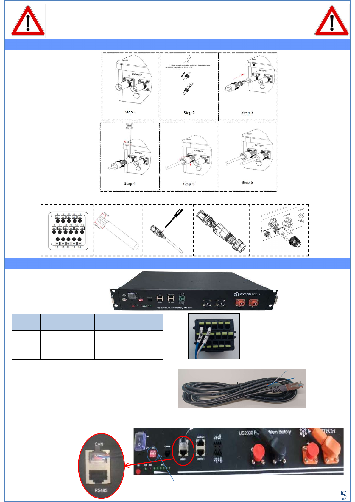
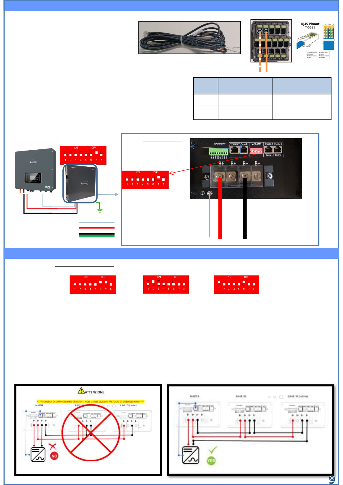
Note: The communication cables are in
the kit that is contained in the WeCo
battery box
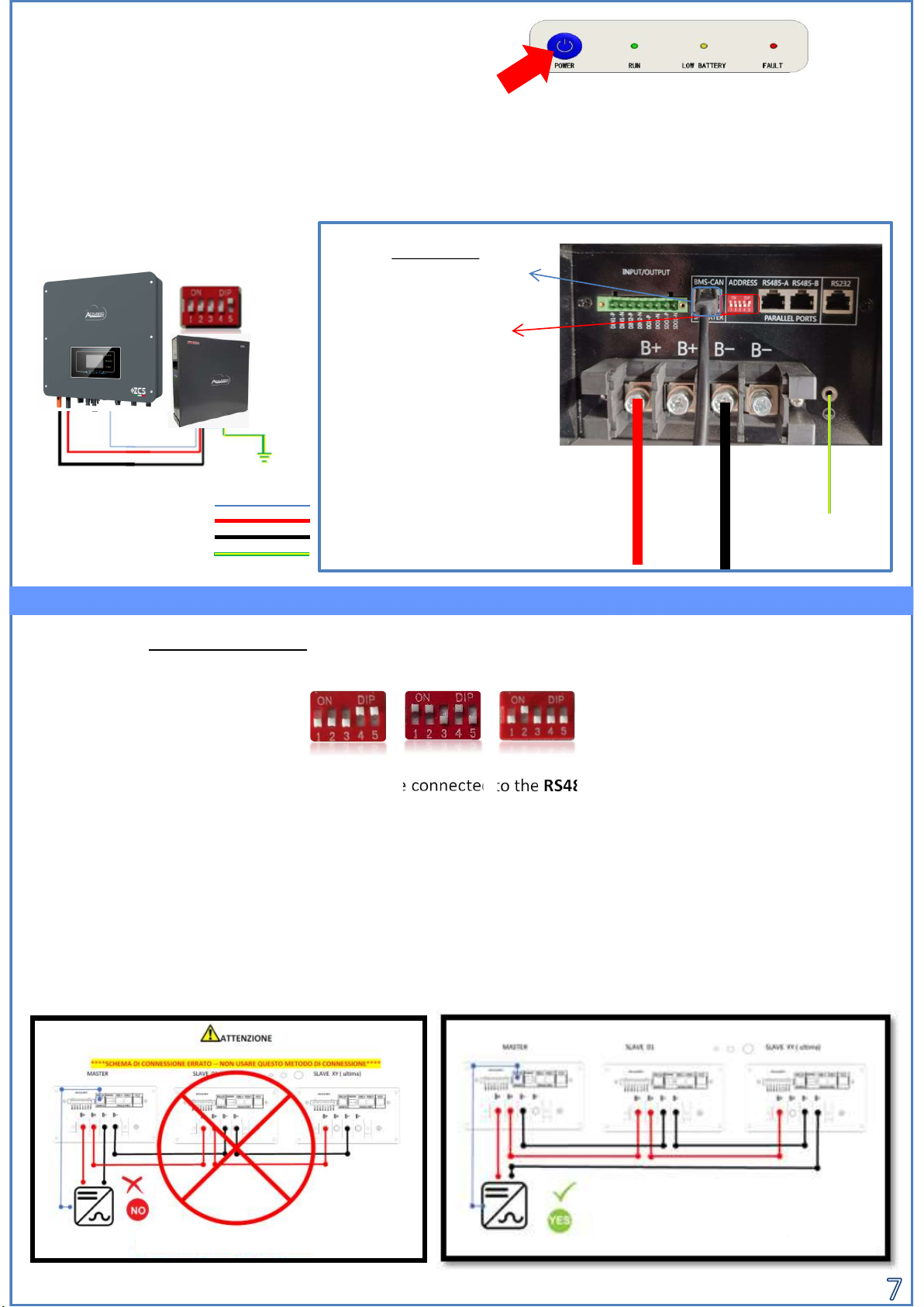
In caso di SINGOLA BATTERIA:
1. Connettere l‘ingresso CAN-A
2. Impostare i DIP Switch come
in figura
3. Le connessioni di potenza
dovranno avvenire agganciando
gli appositi connettori B+ e B-
nell‘ingresso corrispettivo (come
da figura)
4. Collegare il cavo di terra alla
batteria tramite il foro filettato
Cavo comunicazione Inv-Batt
Cavo potenza positivo
Cavo potenza negativo
Cavo di Terra (PE)
In the event of MULTIPLE BATTERIES, connect the communication cable from the CAN port of the inverter to the
CAN-BMS port of the MASTER battery after correctly setting the DIP Switches:
8.6 WECO 4K4PRO BATTERIES IN PARALLEL
The RS485-B port of the MASTER battery must be connected to the RS485-A port of the Slave 1 battery using the
cable provided inside the battery box . (NOTE: the RS485-A port ofthe Master battery will remain not connected).
In case of additional batteries, the communication cable will be connected between the RS485-B port of the previous
battery to the RS485-A port of the following battery.
The last battery will only have the RS485-A port connected.
As for the power connections, all the batteries must be connected in parallel using the power cables supplied, making
sure that the cable does not exceed a length of 2.5 m.
The “NEGATIVE” power cable coming out from the inverter must be connected to the MASTER battery on the
NEGATIVE terminal, while the “POSITIVE” cable must be connected to the last SLAVE N battery on the POSITIVE
terminal.
COLLEGAMENTO NON CORRETTO
COLLEGAMENTO CORRETTO
Note: Turn off the batteries each time the
position of the DIP switches is changed.
presente nella scatola dell’inverter.
PIN
Inverter
Comunicazione
batteria Note
1CAN (white – orange
wire) Communication
between battery BMS
and Inverter2 CAN (orange wire)
Inverter COM connector

MASTER SLAVE 1
MASTER SLAVE 1 SLAVE 2
MASTER SLAVE 1 SLAVE 2 SLAVE 3
MASTER SLAVE 1 SLAVE 2 SLAVE 3 SLAVE 4
Connecting 5
batteries
Connecting 4
batteries
Connecting 3
batteries
Connecting 2
batteries

8.7 SINGLE 5k3 WECO BATTERY
Note: Maximum DoD programmable 90%
Note: The communication and power cables
must be ordered separately
Note: Turn off the batteries each time of
the DIP switches is position changed.
In case of multiple batteries connected in parallel or
when adding new batteries to a system with batteries
already installed and operating, make sure that the
difference between the voltages of all the batteries is less
than 1.5 volts. Each battery must be measured
individually, therefore make sure the batteries are not
connected to each other. (If the value is higher than 1.5
volts, contact Technical Support). To access the battery
connection, remove the cover of the LV section
located on the left hand side by unscrewing the
crosshead screws. See the figure to identify the
LV section
8.7 SINGLE 5k3 WECO BATTERY
Inv-Batt communication cable
Positive power cable
Negative power cable
Ground cable (PE)
Low voltage connector (LV)
High voltage connectors (HV)
Attention: When connecting 5k3 batteries to single-phase Inverter
inverters, only the low voltage section must be used. To prevent
damage to the batteries or inverter, do not use the high voltage
section.
The RS485-B port of the MASTER battery must be connected to the RS485-A port of the Slave 1 battery using the
cable provided inside the battery box . (NOTE: the RS485-A port of the Master battery will remain not
connected).
In case of additional batteries, the communication cable will be connected between the RS485-B port of the
previous battery to the RS485-A port of the following battery. The last battery will only have the RS485-A port
connected.As for the power connections, all the batteries must be connected in parallel using the power cables
supplied, making sure that the cable does not exceed a length of 2.5 m.
The “NEGATIVE” power cable coming out from the inverter must be connected to the MASTER battery on the
NEGATIVE terminal, while the “POSITIVE” cable must be connected to the last SLAVE N battery on the POSITIVE
terminal.
In case of a SINGLE BATTERY:
1. Connect the CAN-A input
2. Set the DIP switches as
shown in the figure
3. Connect the power cables by
attaching the appropriate B+ and
B- connectors to the corresponding
input (as shown in the figure).
4. Connect the ground cable to the
battery through the threaded hole
8.8 WECO 5k3 BATTERIES IN PARALLEL
In case of MULTIPLE BATTERIES, connect the communication cable from the CAN port of the inverter to the
CAN- A port of the MASTER battery after defining the correct positioning of the DIP switches:
PIN
Inverter
Comunicazione
batteria Note
1CAN (white – orange
wire) Communication
between battery BMS
and Inverter2 CAN (orange wire)
Inverter COM connector

MASTER SLAVE 1
MASTER SLAVE 1 SLAVE 2
MASTER SLAVE 1 SLAVE 2 SLAVE 3
MASTER SLAVE 1 SLAVE 2 SLAVE 3 SLAVE 4
Connecting
3 batteries
Connecting 2
batteries
Connecting
4 batteries
Connecting
5 batteries
CORRECT CONNECTION
INCORRECT CONNECTION

8.7 SINGLE 5k3 WECO BATTERY
Note: Maximum DoD programmable 90%
Note: The communication and power cables
must be ordered separately
Note: Turn off the batteries each time of
the DIP switches is position changed.
In case of multiple batteries connected in parallel or
when adding new batteries to a system with batteries
already installed and operating, make sure that the
difference between the voltages of all the batteries is less
than 1.5 volts. Each battery must be measured
individually, therefore make sure the batteries are not
connected to each other. (If the value is higher than 1.5
volts, contact Technical Support). To access the battery
connection, remove the cover of the LV section
located on the left hand side by unscrewing the
crosshead screws. See the figure to identify the
LV section
8.9 SINGLE 5k3XP WECO BATTERY
Inv-Batt communication cable
Positive power cable
Negative power cable
Ground cable (PE)
Low voltage connector (LV)
High voltage connectors (HV)
Attention: When connecting 5k3xp batteries to single-phase Inverter
inverters, only the low voltage section must be used. To prevent
damage to the batteries or inverter, do not use the high voltage
section.
The RS485-B port of the MASTER battery must be connected to the RS485-A port of the Slave 1 battery using the
cable provided inside the battery box . (NOTE: the RS485-A port of the Master battery will remain not
connected).
In case of additional batteries, the communication cable will be connected between the RS485-B port of the
previous battery to the RS485-A port of the following battery. The last battery will only have the RS485-A port
connected.As for the power connections, all the batteries must be connected in parallel using the power cables
supplied, making sure that the cable does not exceed a length of 2.5 m.
The “NEGATIVE” power cable coming out from the inverter must be connected to the MASTER battery on the
NEGATIVE terminal, while the “POSITIVE” cable must be connected to the last SLAVE N battery on the POSITIVE
terminal.
In case of a SINGLE BATTERY:
1. Connect the CAN-A input
2. Set the DIP switches as
shown in the figure
3. Connect the power cables by
attaching the appropriate B+ and
B- connectors to the corresponding
input (as shown in the figure).
4. Connect the ground cable to the
battery through the threaded hole
8.10 WECO 5K3XP BATTERIES IN PARALLEL
In case of MULTIPLE BATTERIES, connect the communication cable from the CAN port of the inverter to the
CAN- A port of the MASTER battery after defining the correct positioning of the DIP switches:
PIN
Inverter
Comunicazione
batteria Note
1CAN (white – orange
wire) Communication
between battery BMS
and Inverter2 CAN (orange wire)
Inverter COM connector

MASTER SLAVE 1
MASTER SLAVE 1 SLAVE 2
MASTER SLAVE 1 SLAVE 2 SLAVE 3
MASTER SLAVE 1 SLAVE 2 SLAVE 3 SLAVE 4
Connecting
3 batteries
Connecting 2
batteries
Connecting
4 batteries
Connecting
5 batteries
CORRECT CONNECTION
INCORRECT CONNECTION

8.11 5K3XP BATTERIES AND 5K3 BATTERIES IN PARALLEL
Connecting 5
batteries:
Master 5K3XP
Slave 1 5K3
Slave 2 5K3
Slave 3 5K3
Slave 4 5K3
MASTER SLAVE 1 SLAVE 2 SLAVE 3 SLAVE 4
Connecting 3
batteries:
Master 5K3XP
Slave 1 5K3
Slave 2 5K3
Connecting 4
batteries:
Master 5K3XP
Slave 1 5K3
Slave 2 5K3
Slave 3 5K3
MASTER SLAVE 1 SLAVE 2
MASTER SLAVE 1 SLAVE 2 SLAVE 3

In case of a SINGLE BATTERY:
1. Connect the CAN input
2. The power connections must be
made by attaching the appropriate
P+ and P- connectors to the
corresponding input (as shown in
the figure).
3. Connect the ground cable to the
battery through the threaded hole
indicated by the ground symbol.
4. Press the button on the front
of the battery to switch it on.
8.12 SINGLE AZZURRO 5000 BATTERY
Note: The communication cable is located inside the kit
in the inverter box.
Note: Maximum DoD programmable 90%
8.13 AZZURRO 5000 BATTERIES IN PARALLEL
Inverter
PIN
Battery
communication Note
1 CAN H (blue wire) Communication between
battery BMS and Inverter
2CAN L white/blue
wire )
Inverter COM
connector
In case of multiple batteries connected in
parallel or when adding new batteries to a
system with batteries already installed and
working, make sure that the difference
between the voltages of all the batteries is
less than 1.5 Volt. Each battery must be
measured individually, so make sure the
batteries are not connected to each other. (If
the value is higher than 1.5 Volt, contact
Technical Support)
In the event of MULTIPLE BATTERIES, connect the communication cable from the CAN port of the inverter to the CAN
port of the MASTER battery. The MASTER battery must be connected to the communication cable found inside the
battery box starting from the LINK OUT port and arriving at the LINK IN communication port of the Slave 1 battery.
(Attention: do not connect the LINK IN port to the Master battery).
In case of additional batteries, the communication cable will be connected as indicated above for the connection of
the MASTER battery to SLAVE 1. The last battery will only have the LINK IN port connected.
As for the power connections, all the batteries must be connected in parallel using the power cables supplied, making
sure that the cable does not exceed a length of 2.5 m.
Batteries power connection shall be done as shown in the below picture and described below:
Positive and Negative power cables shall be connected one to the first battery ( MASTER) and the other to the last
battery (SLAVE N). Connecting
2 batteries Connecting
3 batteries
Connecting
4 batteries
Inv-Batt communication cable
Positive power cable
Negative power cable
Ground cable (PE)

6 7 8 9 10 11
1 2 3 4 5
Fase 2 Fase 3
Correct placment of the current sensor:
•The CT measure the current exchange with the grid, shall be placed at the utility power meter and
include all the phase cable coming out from the meter.
The direction of the CT is not important since the system recognize it at the first power on.
Connect the sensor negative wire in input 13 of the COM connector
Connect the sensor positive wire in input 14 of the COM connector
OK
Inverter
PV Panels
For the extention cable is recomended to use a STP cable cat 6 (8 wires) connecting
4 wire to the positive CT terminal and 4 wire to the negative, or a
2x0,5 mm² shielded cable, is recomended to use flexible wire.
CT
Interruttore di
protezione
9.1 MEASUREMENT OF THE EXCHANGE THROUGH CURRENT SENSOR
Breaker
Exchange meter
PIN definition
13 CT-
14 CT+
+ + + + +
+ + + + +
+ + + + ++
12 13 14 15 16
CT+
CT-
only for distances between Inverter and CT
below 50m
Inverter
PV Panels Interruttore di
protezione
Exchange meter
Breaker
Battery
Battery

The sensor must include all phase cables
entering or leaving the meter.
9.2 MEASUREMENT OF THE EXCHANGE POWER THROUGH METER
INVERTER PIN METER PIN Nota
16 24
Exchange meter communication
15 25
Battery
PV Panels
HYD
Load
Grid
Exchange
meter
Meter LN
Inverter
PV Panels Breaker Exchange
meter
Battery

Connessioni Meter
Meter for
exchange
2. Connect the Meter as shown in the picture:
Connect Neutral cable (N) to Meter’s PIN 2;
Connect phase cable (exchange meter side) to Meter’s PIN 3
Connect phase cable (Solar inverter and loads side) to Meter’s PIN 1
1. Connect Meter and inverter trough the RS485 port.On the
Meter this port is identified by PIN 24 e 25.
On the inverter this port is identified by PIN 16 e 15 on the
COM conector
1. Verify, using the push button
That the Meter is 001.
In the Meter display are visible also:
Current;
Voltage;
Power Factor ;
Power.
NOTE: for distances between Inverter and Meter above 100 m is recomended to connect in the 485 daysy chain 2 120 Ohm resistors, one
between PIN 15 and PIN 16 in the inverter COM port and between PIN 24 and PIN 25 on the meter.
9.3 SETTING METER FOR EXTERNAL PRODUCTION
2. In order to configure the meter reading on the
inverter is required to access the display ( see
picture):
1. Press the first push button on the inverter;
2. Access the advanced setting on the menu;
3. Enter the PWD «0715»;
4. Access submenu 10. Set PCC Meter;
5. Select Enable;
6. Press Ok.
24 25
15 16
Indirizzo Corrente Potenza Tensione Power factor

9.4 MEASUREMENT OF EXTERNAL PRODUCTION THROUGH METER
PIN INVERTER PIN METER Nota
16 24 Communication between
inverter and production meter
15 25
Battery
CT
Connessioni Meter
Meter for external prioduction
Connect the Meter as shown in the picture:
Connect Neutral cable (N) to Meter’s PIN 2;
Connect phase cable (external inverter side) to Meter’s PIN 3
Connect phase cable (loads side) to Meter’s PIN 1
1. Connect Meter and inverter
trough the RS485 port.On the
Meter this port is identified by
PIN 24 e 25.
On the inverter this port is
identified by PIN 16 e 15 on
the COM conector
NOTA: Per distanze fra Meter e inverter Ibrido superiori a 100 metri è consigliato connettere lungo la daisy chain 485
due resistenze da 120 Ohm, la prima all’inverter (fra i PIN 15 e 16 della COM inverter), la seconda direttamente al Meter (PIN 24 e 25).
PV Panels
HYD
Exchange
Meter
LN
Rete
Loads
Meter for
external
prioduction
Inverter
HYD
24 25
15 16
Table of contents
Popular Inverter manuals by other brands

Mecafer
Mecafer MF6500E user manual

Mitsubishi Electric
Mitsubishi Electric FR-S500 Series instruction manual

Agilent Technologies
Agilent Technologies MXG (Series A and B) manual

Mastervolt
Mastervolt 12/700 User and installation manual

Solar Frontier
Solar Frontier PowerSet Turbo Series Installation and operating manual

Frecon
Frecon FR200F Series user manual