Stockmaster Lift-Truk User manual

* Pro Version shown
Assembly
Instructions
CL/INST04
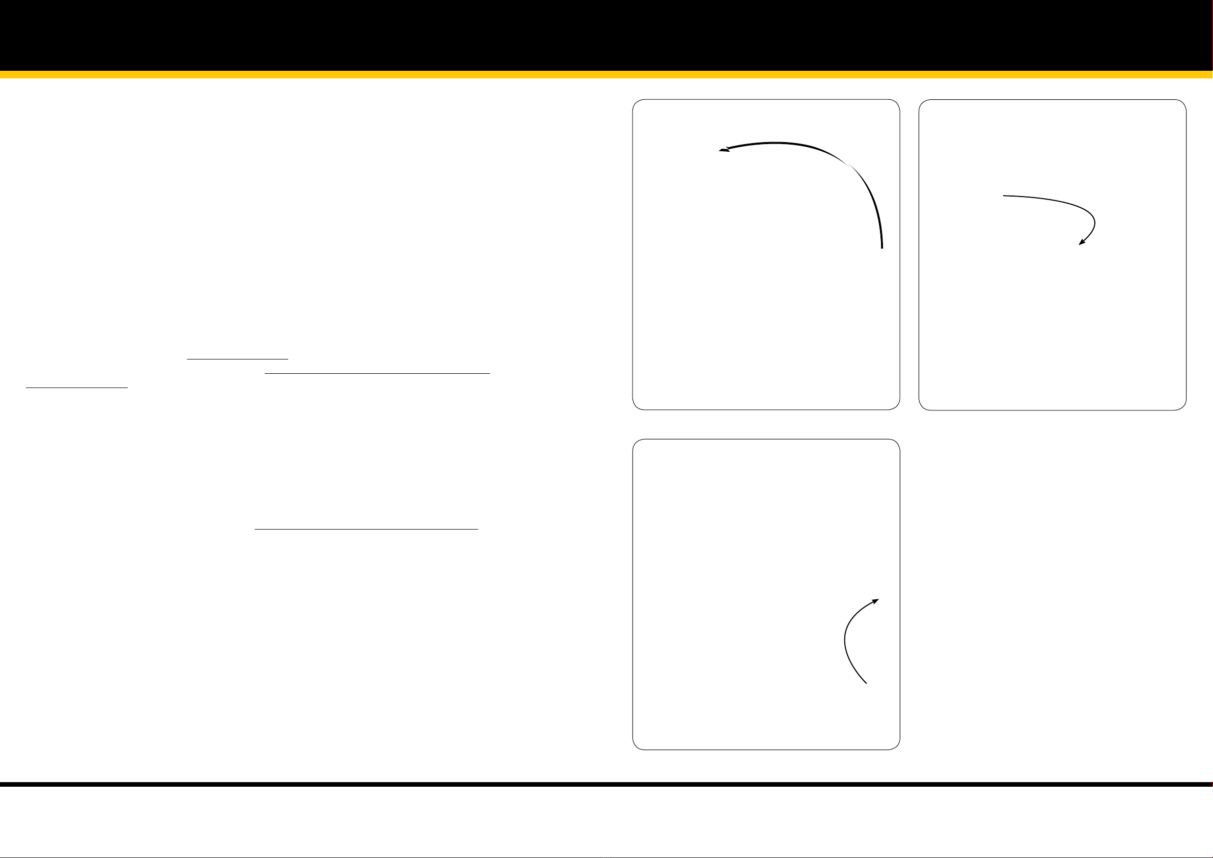
Platform - Safety Rail Assembly Platform - Safety Rail Assembly
M6 x 45
Patch-Lok
M6 x 40
M6 x 70
M6 x 70
Illustration 1 Illustration 2
Illustration 3 Illustration 4
IMPORTANT: To avoid assembly problems follow these instructions exactly.
Note: If assembling the platform with Folding Safety Rails first read the seperate instructions included with the
Folding Safety Rail Bracket Kit.
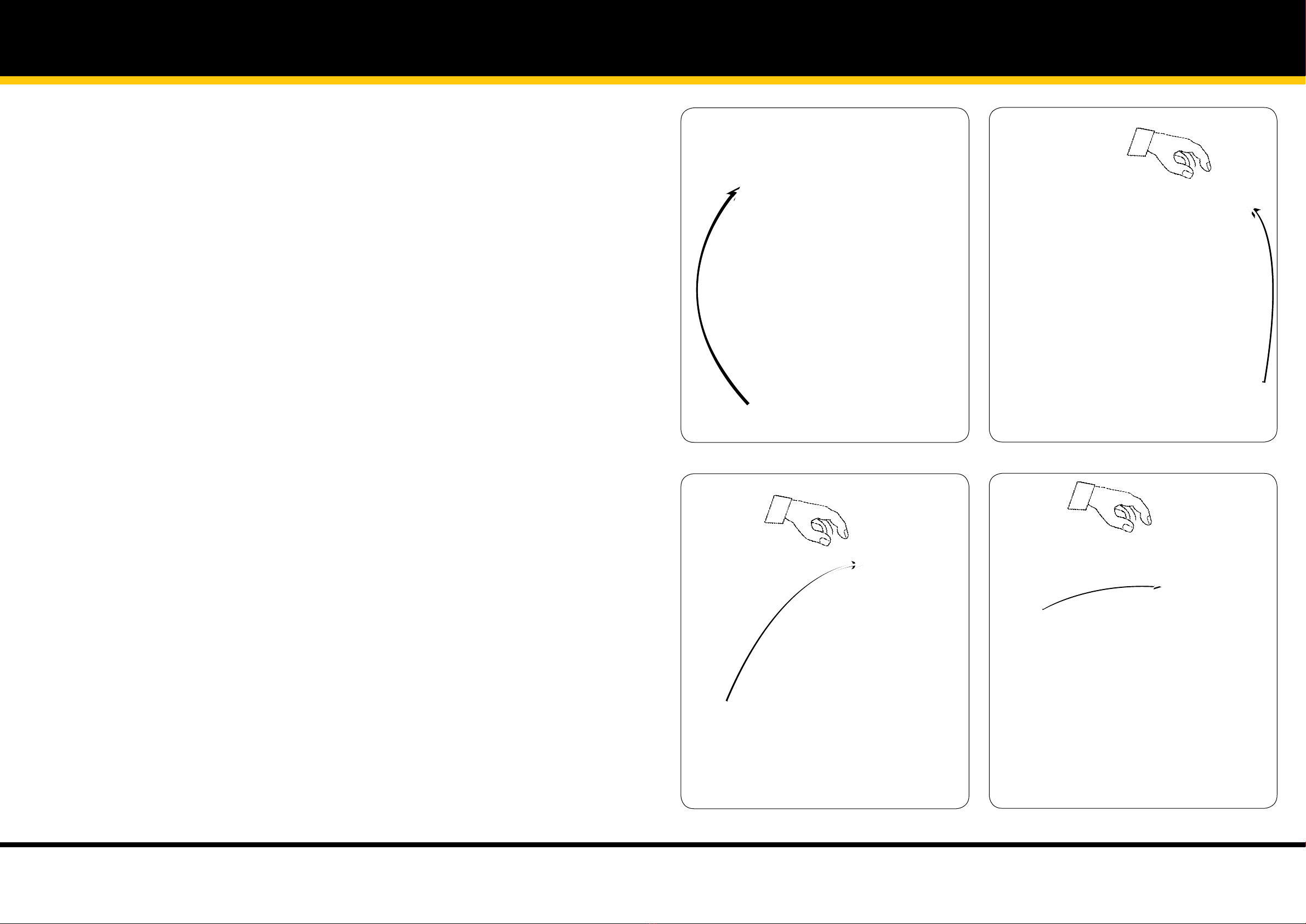
Step 1 - Fix the Rear Safety Rail to the rear of the Platform Kickrail. Use the M6 x 45mm Patchlok bolts (blue
coated) and screw in with the hexagon key leaving the bolt slightly loose (See illustration No. 1)
Note: Do NOT use Pnuematic or Electric drivers with Patch-Lok Fixings
Step 2 - Fix the Lower LH Side Safety Rail to the Platform Kickrail. Slide the Safety Rail into the Kickrail. Place a M6 x
40mm bolt through the top hole at the front of the Kickrail and fit a nut -
Finger tight only
. (See illustration No. 2)
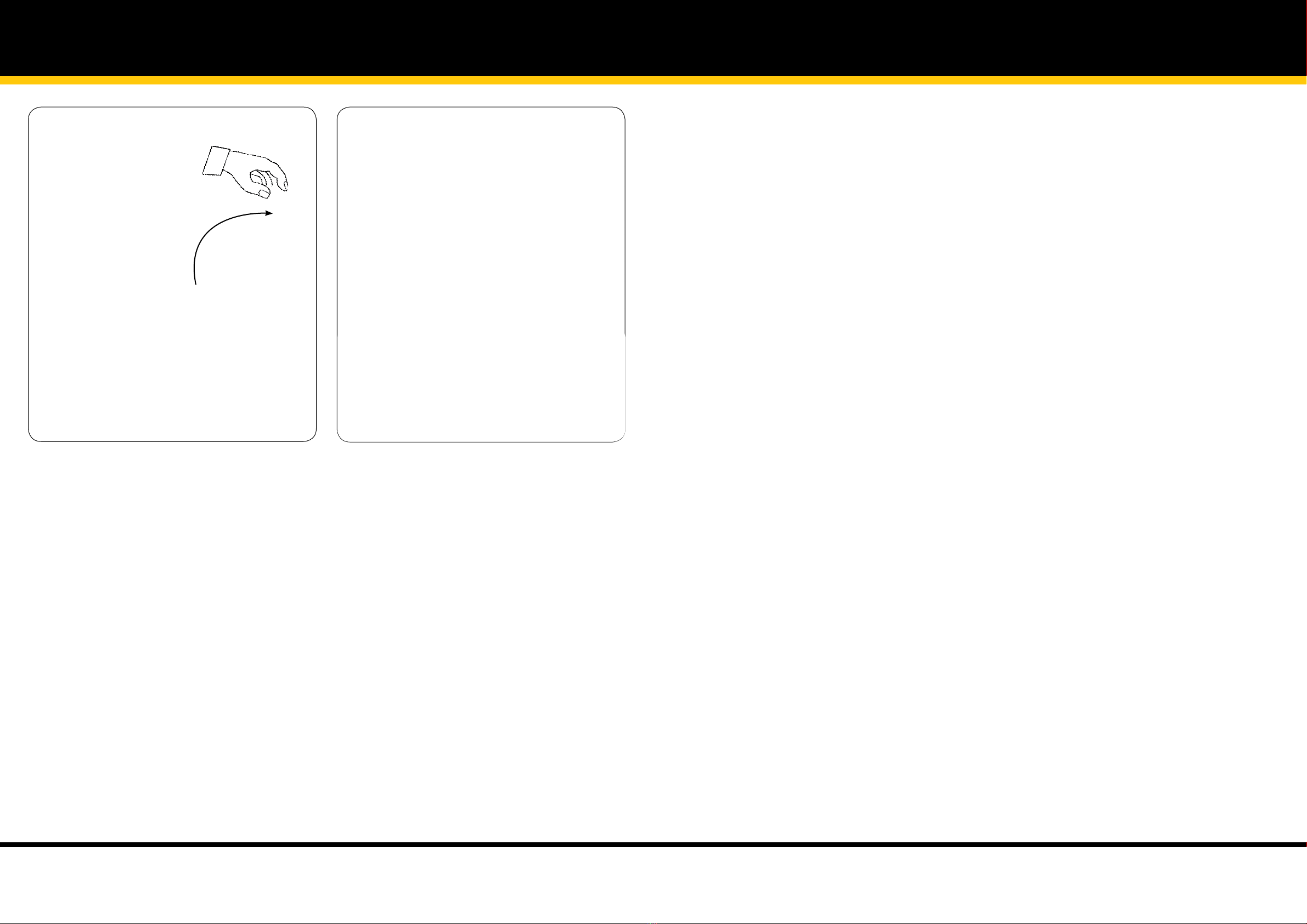
Step 3 - Fix the Lower LH Side Safety Rail to the Rear Safety Rail using two M6 x 65 bolts and nuts -
Finger tight
only.
(See illustration No. 3)
Step 4 -Fix the Upper LH Side Safety Rail to the Rear Safety Rail using two M6 x 65 bolts and nuts.
Finger tight
only.
(See illustration No. 4)
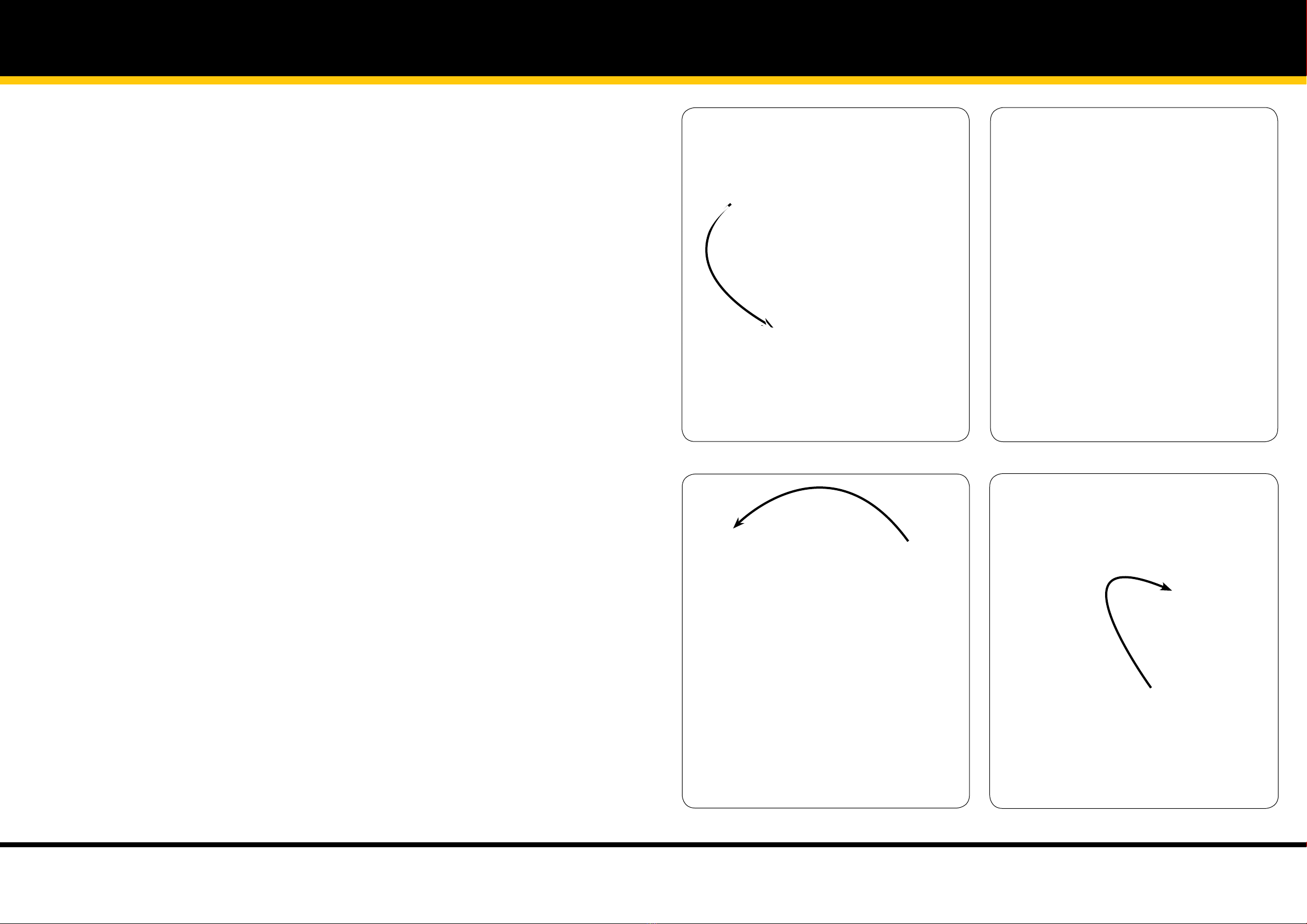
Step 5 - Fix the Upper LH Side Safety Rail to the Lower Side Safety Rail.
Finger tight only.
(See illustration No. 5)
Repeat steps 2 to 5 for the other side rails. PRO Version repeat steps 2 & 3 only. Do not fit the RHS Upper Side
Safety Rail
Step 6 -Check that the rails are all alligned and use the hexagonal key and spanner to tighten all bolts. The M6
bolts must be tightened untill the screw end is flush with the back of the nut. (See illustration No. 6)
1
2
Platform - Safety Rail Assembly
Illustration 5 Illustration 6
M6 x 70
Platform - Safety Rail Assembly
3
4
NEXT: For PRO Models - Proceed to Rota-Gate Assembly 5
NEXT: For Standard Models - Proceed to Ladder Frame Assembly 9
Rota-Gate Assembly
IMPORTANT: To avoid assembly problems follow these instructions exactly.
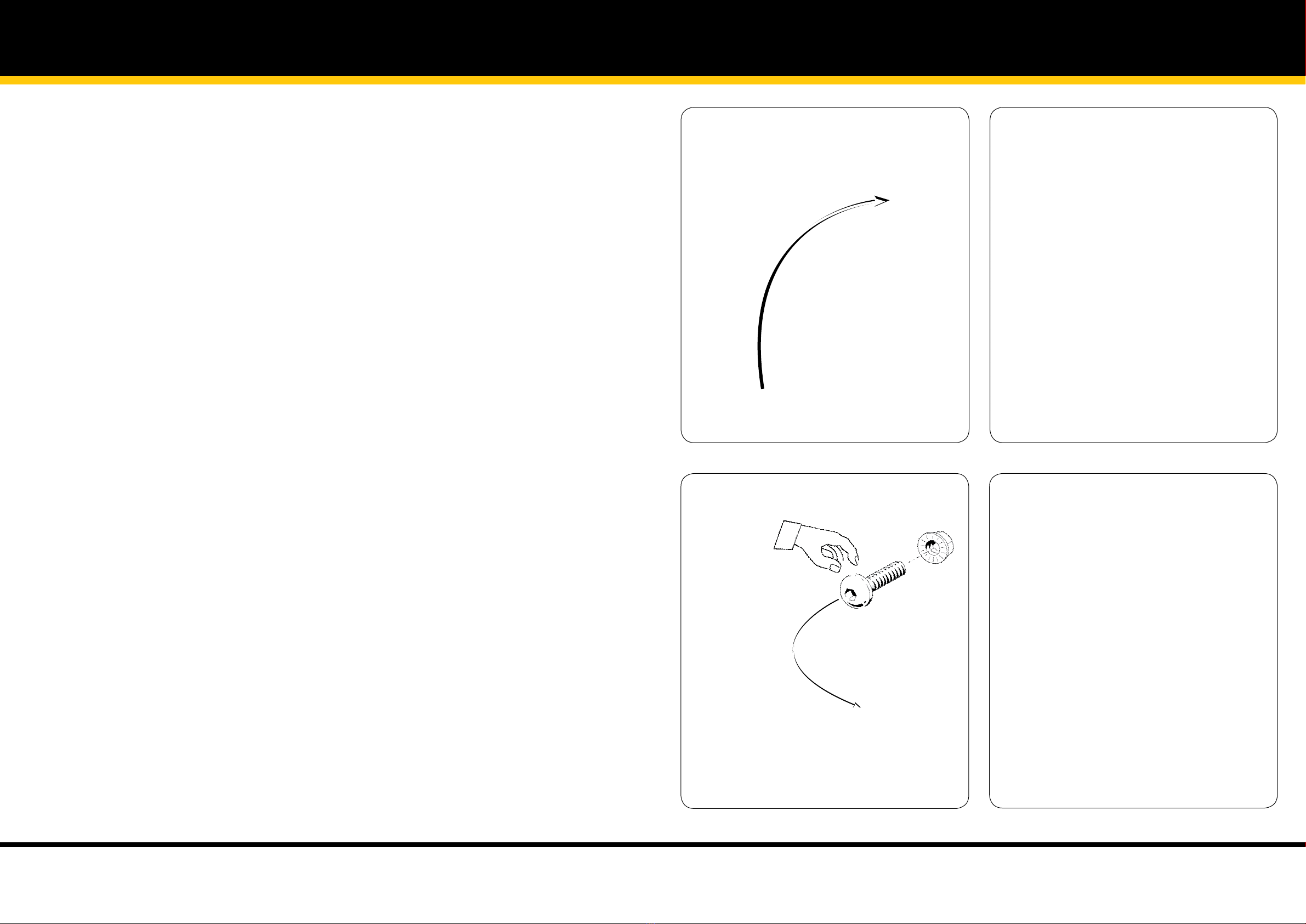
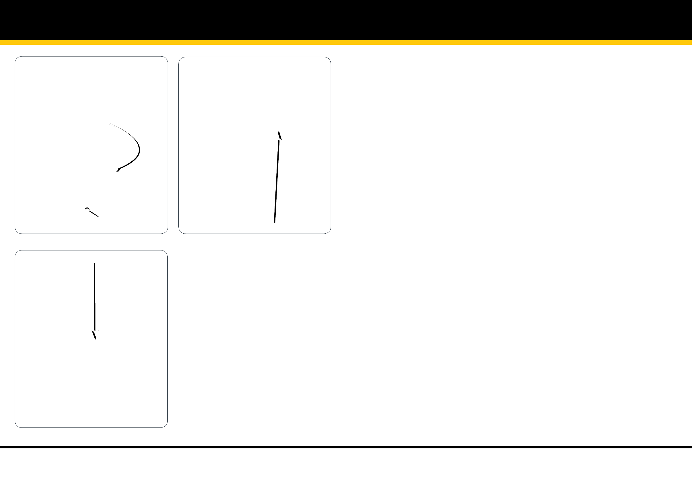
Step 1 - Fasten the Angle Rotating Bracket to the Lower Side Safety Rail at A and B using two M6 x 40mm Bolts and
Nyloc Nuts -
Finger tight only
. (See illustration No. 1)
Step 2 - Attach the Nylon Catch Plate to the inside
of the Rear Safety Rail with two M6 x 50mm
Bolts, Washers and
Nyloc Nuts at C and D -
Finger tight only
. (See illustration No. 2)
Step 3 - Close the Rotating Side Safety Rail as shown. Twist the Locking Knob 1/4 turn so the pin is fully extended
and locate the pin in the Stricker Plate at E.. Tighten all bolts at A thru D untill
firm only.
(See illustration No. 3)
Step 4 -
Open and close the gate thru its full range ensuring it latches closed correctly. The holes in the Catch
plate are elongated for fine adjustement. When all is correct tighten all fixings using the hex key and spanner provided.
(See illustration No. 4)
Rota-Gate Assembly
Illustration 1 Illustration 2
Illustration 3 Illustration 4
M6 x 50
B
A
E
M6 x 40
M6 x 40 C
D
C
D
E
5
6
NEXT: Proceed to Auto-Safe Gate Assembly. 7

Auto-Safe Gate Assembly
IMPORTANT: To avoid assembly problems follow these instructions exactly.
Step 1 - Remove the M6 x 65mm screw and nyloc nut at A from the LHS Upper Side Safety Rail as viewed from the
entry point of the platform and discard. (See illustration No. 1)
Step 2 - Align the Rear Tab of the Auto-Safe Gate Housing with hole position A in the LH Side Upper Safety Railing.
Insert the longer M6 x 70mm screw supplied and tighten with a nyloc nut. (See illustration No. 2)
Step 3 - Fit the supplied U Bolt around the Upper Side Safety Rail and pass thru the holes in the Auto Safe Gate
Housing. Ensure the Gate is level and tighten using the washers and nyloc nuts supplied. (See illustration No. 3)
Step 4 -
Open and close the gate testing the Spring Auto Open Function and that the Gate Latch securely holds
the gate in the closed position. (See illustration No. 4)
Auto-Safe Gate Assembly
Illustration 1 Illustration 2
Illustration 3 Illustration 4
A
M6 x 70
A
M6 x “U” Bolt
M6 x “U” Bolt
7
8
NEXT: Proceed to Ladder Frames Assembly. 9
Ladder Frame Assembly Ladder Frame Assembly
Illustration 1 Illustration 2
Illustration 3 Illustration 4
Flat Brace
M10 x 20
IMPORTANT: To avoid assembly problems follow these instructions exactly. Work Safely - Do not stand the
frames upright when assembling. Place the frames in the positions as shown in the illustrations.
Step 1 -Lay the Rear Frame (without steps) on the floor. Check that the Flat Brace is at the floor level. If not, turn
the frame over. Place the Platform over the frame as shown. (See illustration No. 1)
Step 2 -Place one of the two Tube Braces under the Platform Safety Rail. (See illustration No. 2)
Step 3 - Fix the other Tube Brace, Platform and Rear Frame together using a 10 x 20mm bolt and nut.
Finger tight
only
. For ease, lift the Frame up slightly. Remove the Tube Brace from under the Platform Safety Rail and fit to the other
side. (See illustration No. 3)
Step 4 - Turn the Platform on its side, the Rear Frame will stand up. Place something under the Platform Rails as
illustrated so the centre line of the Rear Frame is approximately parallel to the floor. (The long box may be used for this).
(See illustration No. 4)
Step 5 - Engage the Front Frame (with steps) into the Platform and fix together using a 10 x 20mm bolt and nut.
Finger tight only
. For ease, lift the Frame up slightly. Repeat this step for the other side. (See illustration No. 5)
Step 6 - Fix the free ends of the Tube Braces to the Front Frame using 10 x 20mm bolts and nuts -
Finger tight only
.
Do not tighten the 10mm bolts untill advised. (See illustration No. 6)
9
10

Ladder Frame Assembly
Illustration 5 Illustration 6
M10 x 20
M10 x 20
Ladder Frame Assembly
11
12
NEXT: Proceed to Tube Brace Assembly. 13
Tube Brace Assembly Tube Brace Assembly
Illustration 1 Illustration 2
Illustration 3
A
B
B
A
M10 x 20
M10 x 20
B
B
Nylon Spacer
Nylon Spacer
C
C
D
D
M10 x 45
M10 x 45
IMPORTANT: To avoid assembly problems follow these instructions exactly. Work Safely - Do not stand the
frames upright when assembling. Place the frames in the positions as shown in the illustrations.
Instructions for sizes with 4 to 7 steps including the platform
:
There are no additional Tube Braces to be fitted to these sizes.
Proceed to Control Handle Assembly
Instructions for sizes with 8 to 11 steps including the platform:
See Step 1 only
Instructions for sizes with 12 to 14 steps including the platform:
See all Steps
Step 1 - Fix one of the two shorter Tube Braces to the Front Frame at A using the M10 x 20 bolts and nuts supplied
with the Braces -
Finger tight only
. For sizes 8 to 11 ONLY fix the other end of the Tube Brace at B on the Rear Frame then
turn the ladder over and repeat for the other side. - Note: Do not tighten the M10 bolts until advised.
For sizes 8 to 11 ONLY - Proceed to Control Handle Assembly. (See illustration No. 1)
Step 2 - For sizes 12 to 14. Fix the remaining end of the Shorter Tube Brace and one end of the Middle sized Tube
Brace to the Rear Frame at B using the M10 x 45 bolt, nut and spacer supplied. The Shorter Brace fixes to the outside
of the Frame. Fit the spacer over the bolt on the Inside of the Frame and fix the Middle sized Brace to the inside of the
Frame -
Finger tight only.
(See illustration No. 2)
Step 3 -Fix the remaining end of the Middle sized Brace to the inside of the Front Frame and the Large Tube Brace
to the outside of the Frame at C -
Finger tight only
. Fix the remaining end of the Large Tube Brace at D -
Finger tight only.
Turn the ladder over and repeat for the other side. Note: Do not tighten the M10 bolts until advised. (See illustration No. 3)
13
14
NEXT: Proceed to Control Handle Assembly. 15

Control Handle Assembly
IMPORTANT: To avoid assembly problems follow these instructions exactly. Work Safely -
This assembly is done
with the Stockmaster standing upright.
Step 1 -Stand the Ladder upright.
Position the Control Handle in the Step Frame between the 2nd and 3rd steps.
(See illustration No. 1)
Step 2 - Fix the Control Handle to the Frame. Pass an “E” Pin through the centre hole in the Control Handle and the
Lower hole in the Mounting Angle of the Step Frame and secure with an “E” Clip fitted to the outside ring of the “E” Pin.
(See illustration No. 2)
Step 3 -
Fix the Restraining Cable to the Frame using a M6 x 16 bolt and 2 Washers. Fit a washer to the bolt, pass it
through the loop in the Restraining Cable and fit the second washer. Fit the bolt in the Upper hole of the Mounting Angle
of the Step Frame and secure with a nut. Tighten the bolt using the Double Ended Spanner and Hex Key
(See illustration
No. 3)
Step 4 -
Fix the Restraining Cable to the Control Handle. Use an “E” Pin and pass it through the Upper hole in the
Control Handle. Fit a washer and pass it through the Free Loop in the Restraining Cable and secure with an “E” Clip on the
inside ring of the ”E” Pin.
(See illustration No. 4)
Control Handle Assembly
Illustration 1 Illustration 2
Illustration 3 Illustration 4
Lower Mounting
Angle Hole
Centre Hole
M6 x 16
15
16
NEXT:
For sizes with 4 to 5 steps incl. platform:
Proceed to Mobilisation Assembly Instructions 19
NEXT:
For sizes with 6 to 14 steps incl platform:
Proceed to Handrail Assembly Instructions 17

IMPORTANT: To avoid assembly problems follow these instructions exactly. Work Safely -
This assembly is
done with the Stockmaster standing upright.
Step 1 - Fix the Handrail to the Platform Kickrail. Slide the Handrail into the Kickrail and rotate the handrail so that
the lower end is over the Step. Place an M6 x 40 bolt through the bottom hole at the front of the Kickrail and fit a nut
Finger tight only.
(See illustration No. 1)
Step 2 -
Fix the Handrail to the Step. Place an M6 x 40 bolt through the Handrail and fit the nut under the Step.
Check that the Handrails are correctly aligned and tighten all four bolts using the Hex Key and Double Ended
Spanner.
(See illustration No. 2)
Step 3 -Illustration No. 3 shows completed Handrail assembly.
Handrail Assembly Handrail Assembly
Illustration 1 Illustration 2
Illustration 3
M6 x 40
M6 x 40
17
18
NEXT: Proceed to Mobilisation Assembly. 19

Mobilisation Assembly
IMPORTANT: To avoid assembly problems follow these instructions exactly. Work Safely -
This assembly is
done with the Stockmaster standing upright.
Step 1 - Fix the Mobilisation Rails (Rectangular Hollow Section - RHS) to the Frames at A & B (See illustration No. 1)
Step 2 - Using the M8 x 40 bolts, nuts and sleeves. Pass the bolt through the hole in the Frame Bracket at D, on the
Front Frame. Place a sleeve over the bolt and fit the Rectangular Hollow Section on the inside of the bracket. Secure
with a nut -
Finger tight only
. (See illustration No. 2)
Note: The Mobilisation units are left & right with the
Link Cable C at end A
(See illustration No. 2)
. The bolt heads are
seen from the outer side of the ladder.
Step 3 - Repeat Step 2 at position E on the Rear Frames -
Finger tight only.
(See illustration No. 3)
Step 4 - One at a time, fix the 3 x No Lock Castors and Castor Mounting Angles to the Mobilisation Channels -
One
Directional Lock castor is supplied. Use this Castor at Frame end A
. Pass an M12 x 40 hex head bolt through the
Mobilisation Channel and locate the Castor Mounting Angle over the bolt. Fit the Castor and then a Washer placed inside
the castor body. Secure the Castor with the nut. Tighten the nut with the Spanner provided. The head of the bolt will
refrain from turning as its held in a fixed position between the channel flanges. (See illustration No. 4)
Note: Castor Mounting Angles have two sets of mounting holes. For sizes 4 and 5 use the inside holes. For sizes 6
and larger, use the outside holes.
Step 5 -Press down on the Black Locking Tab On the Directional Lock Castor. Fix the castor as per step 4 with the
Tab positioned in the direction of the arrow. Hold the Castor in the position illustrated as you tighten. (See illustration
No. 5)
Step 6 -Attach the Mobilisation Link Cable to the Control Handle. Fit a Clevis Pin through the lower hole in the
Control Handle. Lift up the Link Cable C. Fit it over the Clevis Pin and secure with an “E” Clip on the inside ring of the
Clevis Pin. (See illustration No. 6)
Mobilisation Assembly
Step 7 - Assemble the 5th wheel assembly (See illustration No. 7)
A). Feed the 62mm long flanged bush from the underside of the yellow buer and through the top of the tube
B). Fit the 12mm Washer to the M12 x 150 hex bolt and feed it down through the bush
C). Place spring over the bolt
D). Screw the smaller threaded bush (flanged sidedown) all the way up the bolt thread.
(Hand tighten to firm only)
E). Fit the Castor to the bolt and then place a washer inside the castor body. Secure the Castor with the nut. Place the
Spanner over the nut, hold the nut in a fixed position and tighten the bolt with the Hex Key untill firm.
Step 8 - Slide the Buer Tube into position and ensure that it is square to the Mobilisation. Align the holes in the
Buer Tube and Mobilisation RHS at E and F. (Use a screwdriver blade to line up the holes) Using the Nylon Anchors at
E and F. Hammer in the steel pins to fix the Buer Tube to the Mobilisation Rails
Step 9 -Ensure the Ladder is standing on a level surface. Stand on the first step taking hold of ladder frame and
flexing it so all four feet sit firmly on the floor. When there is no evidence of rocking, tighten the four Mobilisation to
Frame fixings using the Hex Key and Spanner provided. Now tighten the remaining 10mm bolts in the Ladder Frames
using the Hex Key only.
(Hold the nut in a fixed position with the spanner. Do not rotate the nut.)
Illustration 1 Illustration 2
A B A
D
C
M8 x 40
19
20

Mobilisation Assembly
Illustration 3 Illustration 4
M8 x 40
E
M12 x 40
Illustration 5 Illustration 6
C
Mobilisation Assembly
Illustration 7 Illustration 8
E
F
21
22
NEXT:
For sizes with 4 to 7 steps incl platform:
Proceed to Winch Assembly Instructions 27
NEXT:
For sizes with 8 to 14 steps incl platform:
Proceed to 2 Piece Mast Assembly Instructions 23

2 Piece Mast Assembly 2 Piece Mast Assembly
Illustration 1 Illustration 2
Illustration 3 Illustration 4
M6 x 16
M6 x 16
IMPORTANT: To avoid assembly problems follow these instructions exactly. Work Safely
Instructions for sizes with 12 to 14 steps including the platform:
Step 1 - On a level surface butt the two Mast sections together. (See illustration No. 1)
Step 2 - Fix the Large Mast Joining Plate to the two Mast sections using four of the M6 x 16 button head screws -
Finger tight only.
(See illustration No. 2)
Step 3 - Turn the Mast over. Locate the Small Mast Joining Plates and position them inside the Mast channel and
fasten using four of the M6 x 16 button head screws. Ensure Mast sections are correctly aligned and then tighten all
screws.
(See illustration No. 3)
Step 4 - Lift the Mast as shown cut and remove the Wire Tie then lay the Mast flat on its back again. (See illustration
No. 4)
Step 5 -In the centre of the Mast Channel. Cut and remove the Black Wire Ties holding the chain bundle in position.
(See illustration No. 5)
Note: Do NOT cut the White Wire Tie.
Step 6 -Using the White Wire Tie. Pull the stored chain down the length of the mast untill taught. (See illustration
No. 6)
Step 7 - Loosen the Mast Roller at the base of the Mast (See illustration No. 7)
Step 8 - Using the 2 Black Wire Ties supplied. Tie the chain to the top of the Mast thru the holes A & B. Ensure the
White Wire Tie is located between these two tie positions. (See illustration No. 8)
23
24
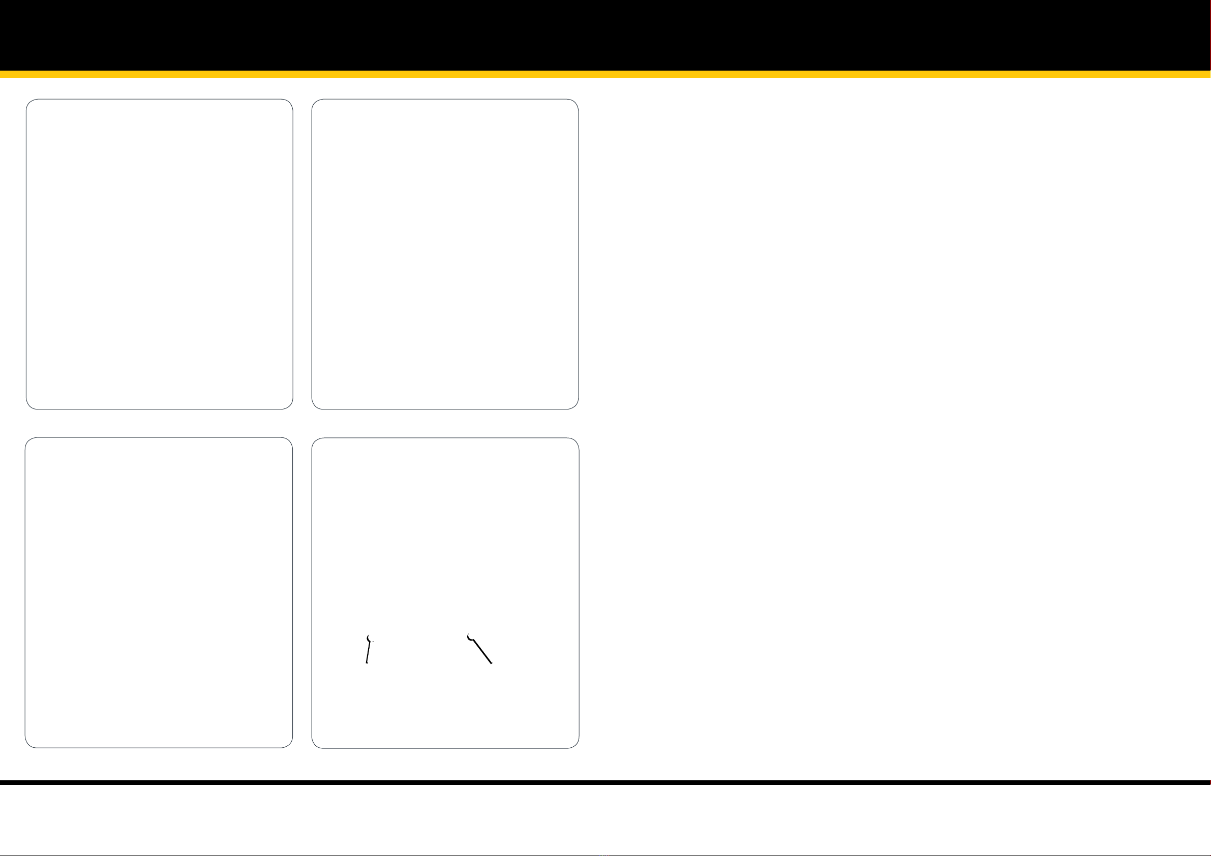
Illustration 5 Illustration 6
Illustration 7 Illustration 8
A B
2 Piece Mast Assembly 2 Piece Mast Assembly
25
26
NEXT: Proceed to Winch Assembly. 27

IMPORTANT: To avoid assembly problems follow these instructions exactly.
Step 1 - On a level surface lay the mast face-down as shown. (See illustration No. 1)
Step 2 - Remove the Nut from the Winch Shaft at A. Pull out the winch shaft and remove the Sproket. Carefully put
the Sproket, Shaft, Nut & Washer aside. Parts to be re-assembled in Step 4. (See illustration No. 2)
Step 3 - Place the Winch Body inside the opening on the back of the Mast. Insert the Winch Body at 45 degrees so
the Chain fits inside the Winch Body.(See illustration No. 3)
Step 4 - Fix the Winch Mounting Bracket to the Mast at B & C using two of the M6 x 16 button head screws and nyloc
nuts.
Finger tight only.
(See illustration No. 4)
Step 5 - Adjust the Winch Mounting Bracket so you can slide the Sproket back into place. Insert the Winch Shaft at
Dand re fit the washer and nut. Fix the Winch Mounting Bracket to the Mast at Eusing an M6 x 16 button head screw and
nyloc nut. Tighten the Winch Shaft and nut firmly then tighten the Winch Mounting Bracket screws and nuts at B, C, & E
(See illustration No. 5)
Winch Assembly
Illustration 1
Winch Assembly
Illustration 2 Illustration 3
Illustration 4 Illustration 5
A
B
C
M6 x 16
E
DM6 x 16
27
28
NEXT: Proceed to Chain Setting. 29

Chain Settting
IMPORTANT: To avoid assembly problems follow these instructions exactly.
Step 1 - Cut and remove the Black Wire Ties at the top of the Mast. Do not cut the Large White Centre Tie
(See illustration No. 1)
Step 2- Position the Chain around the Sprocket using the Large White Wire Tie. Once the Chain is engaged correctly,
cut and remove the Wire Tie. (See illustration No. 2)
Step 3 - Slide the Chain Roller toward the bottom of the Mast to tension the Chain. Check that the Chain is engaged
with the roller and tighten the screw and nut. (See illustration No. 3)
Chain Setting
Illustration 1 Illustration 2
Illustration 3
29
30
NEXT: Proceed to Mast Assembly. 31

Mast Assembly
IMPORTANT: To avoid assembly problems follow these instructions exactly. Work Safely -
This assembly is
done with the Stockmaster standing upright.
Step 1 - Lift the Mast into position against the rear of the Platform safety rail and fix thru holes A and B using M6 x
40mm bolts and nyloc nuts. (See illustration No. 1)
Step 2 - Fix the mast to the Platform at C and D using M8 x 20mm bolts and nyloc nuts. (See illustration No. 2)
Step 3 - Ensure the mast is vertical and on centre of the rear frame. If necessary, adjust the Mast by loosening the
nuts in steps 1 and 2. Retighten the bolts after adjusting. Fit the Mast Clamp to the bottom of the mast lining up the bolt
with the hole at the Mast centre. (See illustration No. 3)
Step 4 - Place the Winch Cover over the Winch. Fix the top of the cover to the C slots of the Mast using the Self
Tapping Screws at E and F. (See illustration No. 4)
Step 5 - Fix the bottom flange of the Winch Cover at G to the Mast with an M6 x 16mm bolt and nyloc nut. Fix the
Winch Handle, Washer and nyloc nut to the Winch shaft and tighten. (See illustration No. 5)
Step 6 - Rotate the Winch Handle to raise the Mast carraige approximately 300mm up the Mast. (See illustration
No. 6)
Step 7 - Re-tension the Chain Roller at the bottom of the Mast by loosening the nyloc nut on the inside of the mast
and sliding the Chain Roller down. Hold the Chain Roller in this position and re-tighten the nut. (See illustration No. 7)
Mast Assembly
Illustration 1 Illustration 2
Illustration 3
D
D
C
C
A B
M6 x 40
M8 x 20
Mast Clamp
Illustration 4
FE
31
32
Mast Assembly
Illustration 5 Illustration 6
Illustration 7
G
G
Mast Assembly
33
34
NEXT: Proceed to Lift Table Assembly. 35

IMPORTANT: To avoid assembly problems follow these instructions exactly.
Work Safely -
This assembly is done with the Stockmaster standing upright.
Step 1 - Position the Carraige Rollers of the Upper and Lower Table Brackets within the side track of the Mast.
(See illustration No. 1)
Step 2 - Fix the Upper Table Bracket to the top hole in the Mast Carraige using the M10 x 20mm bolts and nyloc
nuts. Repeat for the other side.
Leave bolts slightly loose
.(See illustration No. 2)
Step 3 - The Lower Table Brackets can be fitted to the Mast Carraige at one of 2 positions. The Upper hole in the
Mast Carraige is for Lift-Truk models and the Lower hole is for Mezzalift. Using the M10 x 20mm bolts and nyloc nuts,
Fix the Lower Table Brackets to the Mast Carraige at the hole position relative to your model.
Leave bolts slightly loose
.. (See illustration No. 3)
Step 4 - Fix the Lift Table to the Table Brackets using the M6 x 25mm bolts and nyloc nuts. Tighten the nuts and
then tighten the Table Bracket to Mast Carraige bolts. (See illustration No. 4)
IMPORTANT:Test the unit before use. Place a minimum load of 20kg on the Lift Table and
Raise the Lift Table up approximately half a meter. The Table must not move when the Winch
Handle is released. If the Table moves, DO NOT USE and contact your supplier for instructions.
Illustration 3 Illustration 4
M6 x 25
M10 x 20
Illustration 1 Illustration 2
M10 x 20
Lift-Truk Models
Mounting Hole Position
MezzaLift Models
Mounting Hole Position
Lift Table Assembly Lift Table Assembly
35
36

Table of contents
Other Stockmaster Lifting System manuals

Popular Lifting System manuals by other brands


Walker Magnetics
Walker Magnetics NEO-1000 Operation manual

VMI
VMI Elite installation manual

HWH
HWH 310 SERIES Operator's manual

rav
rav KPS306HER Translation of the original instructions

Tecnimoem
Tecnimoem Powerlift Up 1 user manual

Custom Equipment
Custom Equipment Hy-Brid Lifts HB 1030CE MAINTENANCE & TROUBLESHOOTING MANUAL

Nostolift
Nostolift XS240 operation & maintenance

global lift corp
global lift corp COMMERCIAL Series installation manual

rav
rav VARKPH 370.32/T Translation of the original instructions

AMF-BRUNS
AMF-BRUNS Easy-Flex-Ramp operating instructions

STARKE ARVID
STARKE ARVID Inlift Instructions for use

Ravaglioli
Ravaglioli RAV 725 N manual