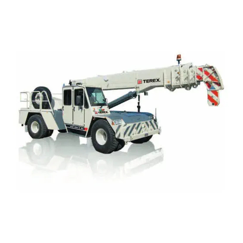
Nostolift XS240 Troubleshooting guide

XS240
SELF-PROPELLED
TELESCOPIC PLATFORM
OPERATION
MAINTENANCE

®
XS 240
SELF-PROPELLED TELESCOPIC PLATFORM
1 INTRODUCTION ................................................................................................................ 2
2 TRANSPORT DIMENSIONS .............................................................................................. 3
3 LIFTING THE ACCESS PLATFORM WITH LIFTING HOOK ............................................ 4
4 SPECIFICATION ................................................................................................................ 5
5 TECHNICAL DATA ............................................................................................................. 7
6 GENERAL SAFETY INSTRUCTIONS ............................................................................. 11
7 MAXIMUM SLOPE ........................................................................................................... 14
COMBUSTION ENGINE ................................................................................................... 15
9 CONTROLS AND FUNCTIONS ....................................................................................... 15
10 DRIVING THE ACCESS PLATFORM ............................................................................ 19
11 USE OF OUTRIGGERS ................................................................................................. 21
12 PRIMARY CONTROLS OF KUBOTA V1505 ................................................................. 24
13 PROCEDURES BEFORE TAKING THE ACCESS PLATFORM INTO USE ................. 26
14 CHECKING THE VOLUME OF AND ADDING HYDRAULIC OIL ................................. 35
15 SOIL TIGHTNESS TABLE ............................................................................................. 36
16 LOCATION OF SAFETY LIMITS AND ELECTRIC COMPONENTS ............................. 37
17 TOWING THE ACCESS PLATFORM ............................................................................ 3
1 PROCEDURES BEFORE TRANSPORTING THE ACCESS PLATFORM .................... 3
19 MAINTENANCE .............................................................................................................. 39
20 PROBLEMS IN OPERATING THE ACCESS PLATFORM ............................................ 50
21 INSTRUCTIONS AND RECORDS FOR RE-INSPECTION ........................................... 51
22 TERMS OF WARRANTY FOR NOSTOLIFT XS ACCESS PLATFORMS .................... 59
23 WARRANTY COMPENSATION APPLICATION ............................................................ 61
24 BILL OF DELIVERY ........................................................................................................ 62
25 WARRANTY ................................................................................................................... 63
26 DIRECTIVES AND STANDARDS APPLIED .................................................................. 64
27 EU DECLARATION OF CONFORMITY FOR MACHINERY ......................................... 65
2 ACCESS PLATFORM INSPECTION RECORD ............................................................ 67
1

®
XS 240
SELF-PROPELLED TELESCOPIC PLATFORM
1 INTRODUCTION
Nostolift XS 240 is a Self-Propelled
Telescopic Access Platform provided
with its own diesel engine. Due to its
four-wheel drive and four-wheel
steering, Nostolift XS 240 is very
agile and can easily travel in difficult
terrain when driven from the platform.
Because all essential controls are
centralized to the platform, the
Nostolift XS 240 Access Platform is
controllable from the platform in any
normal operating situation.
Correspondingly, the electrical box
and the controls for ground operation
are located on the turntable.
The brakes of the Access Platform
get automatically locked when the pressure of the drive motors decreases.
The electrical emergency lowering system can be controlled from the platform and from
the turntable.
Due to its telescopic boom, Nostolift XS 240 has a wide side reach, and the work is also
facilitated as the slewing mechanism rotates without limitation. The jib boom as standard
equipment ensures agile movements.
Nostolift XS 240 Access Platform is provided with many safety-improving functions. To
achieve good, effective and safe working results, their instructions must be read through
carefully. The operation of the Access Platform is made easier by the electric joystick
control of the boom.
The condition of the Access Platform must be inspected daily on the basis of this manual
before starting the work. Do not use the Access Platform if it is not in order or if it has not
been maintained or inspected.
The manufacturer reserves the right to change the construction, equipment as well as the
maintenance instructions of the machine without advance notification.
With wishes of elevating success
NOSTOLIFT OY
2

®
XS 240
SELF-PROPELLED TELESCOPIC PLATFORM
2 TRANSPORT DIMENSIONS
Figure 1. Transport dimensions
Dimension mm in. Dimension mm in.
A 7150 2 1.5 K, wide tyre 340 13.4
B (depending on
tyres)
2335 91.9 K, all-terrain tyre 270 10.6
C 355 14.0 ØL, wide tyre 750 29.5
D 430 16.9 ØL, all-terrain tyre 760 29.9
E 2290 90.7 M, wide tyre 2070 1.5
F 1275 50.2 M, all-terrain tyre 1915 75.4
G 1670 65.7
H 1500 59.1
J 1000 39.4
3

®
XS 240
SELF-PROPELLED TELESCOPIC PLATFORM
3 LIFTING THE ACCESS PLATFORM WITH LIFTING
HOOK
Figure 2. Lifting the Access Platform with lifting hook
m ft.
E Distance of centre of gravity 1,25
F Distance of centre of gravity 1,04
P Centre of gravity
4

®
XS 240
SELF-PROPELLED TELESCOPIC PLATFORM
4 SPECIFICATION
Figure 3. Specification
5

®
XS 240
SELF-PROPELLED TELESCOPIC PLATFORM
1. Platform
2. Boom
3. Turntable
4. Combustion engine
5. Controls on the platform: boom/platform, outriggers, and driving
6. Controls for ground operation of boom
7. Chassis
. Front axle, rocker axle
9. Front wheel and brakes
10. Rear axle, dead
11. Rear wheel and brakes
12. Jib
13. Pivot bearing
14. Slewing motor, gear and brake
15. Fuel tank, filling on the left side of the Access Platform
16. Hydraulic oil tank, on the left side of the Access Platform
17. Battery, at the rear edge of the turntable under a cover
1 . Equipment case, place for manual, ground fault circuit interrupter 220 V 50 Hz
19. Main power switch, at the rear edge of the turntable
20. Lifting cylinder
21. Telescope cylinder
22. Stabilizer cylinder for platform
23. Jib cylinder
24. Steering cylinders
25. Hydraulic pump
26. Limiter device for lifting radius
27. Platform load control device
2 . Foot pedal (when pressed down: operating the boom)
29. Electric pump for the emergency lowering system
30. Control cylinder for stabilizer cylinder
31. Platform step
32. Cylinder for rotating the platform
33. Fastening hooks for safety harness
34. Electric outlets for power tools (220 V 50 Hz)
35. Transport support
6

®
XS 240
SELF-PROPELLED TELESCOPIC PLATFORM
5 TECHNICAL DATA
Max. height of platform bottom from ground.................................22.00 m (72’ 2”)
Max. working height......................................................................24.00 m (7 ’ 9”)
Min. lifting radius measured from the outer edge of platform
with max. working height...............................................................1.4 m (4’ 7”)
Max. permitted platform load.........................................................230.0 kg (507 lbs)
Max. lifting radius with 230.0 kg platform load
(to the edge of platform)................................................................9.4 m (30’ 10”)
Max. lifting radius with 120.0 kg platform load
(to the edge of platform)................................................................10.7 m (35’ 1”)
Max. lifting radius with 0.0 kg platform load
(to the edge of platform) ...............................................................11.3 m (37’)
Dimensions of platform bottom.....................................................1.0 x 1.5 m (3’ 3” x 4’ 11”)
Hydraulic rotating of platform........................................................90°
Slewing angle of jib boom.............................................................120°
Support distance of outriggers (lengthwise).................................5200 mm (17’ 1”)
Support distance of outriggers (width wise)..................................4500 mm (14’ 9”)
Max. supporting force on the sole of outrigger.............................37000 N ( 320 lbs)
Max. allowed slope of the ground.................................................±7°
Max. allowed inclination of the chassis.........................................±1°
Transport length............................................................................7.15 m (23’ 5”)
Transport width..............................................................................2.07 m (6’ 9”)
Transport height (depending on the tyres)....................................2.335 m (7’)
Ground clearance under bottom...................................................0.43 m (1’ 5”)
Wheelbase....................................................................................2.29 m (7’ 6”)
Turning radius:
4-wheel steering, outermost side of tyre.......................................3.0 m (9’ 10”)
4-wheel steering, outermost part of platform................................5.0 m (16’ 5”)
2-wheel steering, outermost side of tyre.......................................4.4 m (14’ 5”)
2-wheel steering, outermost part of platform................................6.4 m (21’)
Rocking angle of front axle............................................................±10°
Total weight with filled tanks.........................................................4 50 kg (10700 lbs)
Rear axle load with 0 kg platform load........................................2430 kg (5360 lbs)
Front axle load with 0 kg platform load.......................................2500 kg (5510 lbs)
Driving speed:
slow...............................................................................................0 - 3 km/h (0 – 1,9 mph)
fast.................................................................................................0 - 5 km/h (0 – 3,1 mph)
Traction force:
slow, oil temperature +20°C........................................................15400 N, 1740 kg
(3 30lbs)
fast, oil temperature +20°C...........................................................7700 N, 70 kg (1915lbs)
Hill climbing capacity (theoretical): slow speed range..................19º (35%)
All-terrain tyres, traction pattern....................................................10.0/75-15.3/ pr
Wide tyres.....................................................................................350/50 – 16/12 pr
Max. noise level (2500 rpm) at ground operating point................91 dbA
7

®
XS 240
SELF-PROPELLED TELESCOPIC PLATFORM
when operated from the platform................77 dbA
Output of hydraulic pump at 2400 rpm..........................................max. 43 l/min (11,4 gpm)
Hydraulic pressure: boom.............................................................230 bar
- drive motors and outriggers........................................................250 bar
Hydraulic pump: axial variable displacement piston pump
Volume of hydraulic oil tank..........................................................60 l (15, gal)
Volume of fuel tank.......................................................................60 l (15, gal)
Combustion engine.......................................................................Kubota V1505-BB-EC-1
Kubota V1505-BB-EC-1:
Output at rotation speed 2400 rpm...............................................30 hp/22 kW
Max. torque at 2400 rpm (ISO 3046)............................................90 Nm
Fuel: light fuel oil, diesel oil ASTM D 975-1D/2D
Fuel consumption at rotation speed 2600 rpm.............................4,7 l/h
Batteries........................................................................................two batteries: 12 V 55 Ah
Warning and indicator lights:
- Oil pressure indicator light
- Charge indicator light
- Indicator light for the overheating of coolant
- Indicator light for malfunction in the control system
Warning texts in Iqan display:
- Fuel volume
- Hydraulic oil volume

®
XS 240
SELF-PROPELLED TELESCOPIC PLATFORM
5.1 NOSTOLIFT XS 240 BOOM GEOMETRY
9

®
XS 240
SELF-PROPELLED TELESCOPIC PLATFORM
10

®
XS 240
SELF-PROPELLED TELESCOPIC PLATFORM
6 GENERAL SAFETY INSTRUCTIONS
1. Read through this owner’s manual carefully before commissioning the Access Platform.
The Access Platform shall never be operated by an operator who is not familiar with the
operating and safety instructions. Store the owner’s manual in the equipment case.
ALWAYS keep the manual with the Access Platform.
2. The operator must be at least 1 years of age and have reasonable operating
experience of Access Platforms. In practice, the owner/holder of the Access Platform must
make sure that each operator is trained.
3. Nostolift XS 240 is fitted with the following fail-safe safety limit switches:
- support position of outriggers
- ground contact of outriggers
- electric safety limit of maximum permitted lifting radius for raising function, telescope, jib,
and electric backup limit switch for lifting radius
- electric safety limit for excess platform load
- safety limit for the transport position
4. The emergency lowering system consists of an electric pump located in front of the
hydraulic oil tank and of the controls for the boom on the turntable and on the platform. For
detailed instructions, refer to chapter "Use of emergency lowering system" in this manual.
5. Avoid rising near live electrical conductors. The minimum safe distance to cables with
different voltage is shown on a sticker on the platform.
6. Always use a yellow flashing warning light when working on streets with busy traffic.
The working zone shall be fenced to avoid risks. Also observe the relevant traffic
regulations concerning the working site.
7. When driving the Access Platform, the boom shall always be supported in the transport
position.
. A maximum of two (2) persons with tools and supplies are allowed on the platform at
the same time, however, so that the total load does not exceed 230 kg.
9. Only use the Access Platform with the outriggers well supported. Use extra plates under
the outriggers, if needed. Make sure that an outrigger does not slip on the surface of the
extra plate and that the extra plate withstands the weight of the outrigger. On icy surface,
attach calks or bolts to the outrigger plates. The sole plates have been provided with holes
for calks. For the tightness of different soil types, refer to the Soil tightness table under
chapter 15. Remember that even asphalt may yield!
10. When operating the Access Platform, observe the adverse impact of wind, rain,
temperature, thunder, bad visibility and accumulated snow and ice.
11. Do not take extra load while lifting. RISK OF TIPPING OVER!
11

®
XS 240
SELF-PROPELLED TELESCOPIC PLATFORM
12. Be aware of the health risk in hot or chilly working environment.
13. Do not increase the wind load of the Access Platform with extra cover boards or load
which enlarge the wind surface.
14. Do not increase the reach or working height of the platform by using planks, ladders or
any other device. Do not swing or jump in the platform.
15. Do not throw down objects from the platform. Make sure that nothing can fall down.
16. Use ear protection when operating the Access Platform from the ground operating
point, because the sound intensity exceeds 4 db (A). When operating the Access
Platform from the platform, the sound intensity is less than 4 db (A), and the use of ear
protection is not obligatory.
17. Always when you operate the Access Platform indoors or in a place with poor
ventilation, the engine shall only be used for moving the Access Platform. Try to intensify
the ventilation. Risk of intoxication! As an accessory, the Access Platform can be
equipped with a mains current pump unit for operation indoors.
1 . Do not use the Access Platform as a crane for transporting goods or persons between
different levels or floors.
19. Do not deactivate a safety device, but repair it or have it repaired by a competent
maintenance shop before re-use.
20. Ensure that the area below the platform is clear of all personnel and obstructions
before lowering the platform.
21. To ensure safe and trouble-free functioning of the Access Platform, keep it free from
snow, ice and other impurities.
22. Be very careful when handling fuels, lubricating and hydraulic oils as well as
lubricating greases of the Access Platform. Avoid skin contact with these. Risk of
exposure!
23. Always turn off the engine of the Access Platform when filling the fuel tank. Beware of
splashes. Risk of fire!
24. Check and maintain the Access Platform regularly or let a maintenance shop familiar
with Access Platforms carry out the service and repair work.
25. Do not make or cause to make any structural alterations to the Access Platform
without the permission and instructions of the manufacturer.
26. Do not open the filling opening of the cooling system if the engine is warm. Risk of
accident!
12

®
XS 240
SELF-PROPELLED TELESCOPIC PLATFORM
27. Check the following issues daily before starting the work:
27.1 Checking the outriggers:
- Refer to the instructions in chapter "Checking the safety limits of outriggers".
27.2 Checking the telescope:
- Refer to the instructions in chapter ”Checking the reach of telescope”.
27.3 Checking the lifting function:
- Refer to the instructions in chapter ”Checking the lifting radius”.
2 . Check the functioning of the backup safety limit for load control once a month. (Refer
to checking instructions in chapter ”Checking the backup safety limit for load control”.)
29. Carry out or cause to carry out a thorough inspection of the Access Platform once in
every twelve (12) months. Carry out a new inspection within a shorter period of time if the
Access Platform is used in demanding conditions, if the load-bearing structures have been
welded or if there is some other special reason for a new inspection. The annual
inspection shall be performed by a person with a valid qualification certificate granted by
an inspection organisation concerning the inspection of Access Platforms.
A dated record of this inspection shall be drawn up, and the record must be kept with the
Access Platform at all times, stored e.g. in the equipment case, and the owner must keep
a second copy. A model of an official record form is enclosed to this manual.
Alterations and repairs, their location on the Access Platform, date, and identity of the
person(s) carrying out repairs and alterations shall be marked in the inspection record.
Keep yourself up to date about developments in the field, check any retroactive
amendment of laws and decrees since the last inspection, and take potential amendments
into consideration when re-inspecting. Prior to repairs or alterations of load-bearing
constructions, the manufacturer or his authorized representative shall always be
contacted.
Test loading of the Access Platform with overload must be performed after any repairs or
replacement of parts on the platform, jib, boom, turntable, chassis, outriggers or cylinders.
30. When leaving the Access Platform, always drive it out of way. Put the boom and
outriggers in the transport position. As protection against unauthorized use, switch off the
engine, remove the ignition keys from both the platform and the control panel of ground
operating point, and switch off the main current. Remove all keys and keep them always
together in one key ring, also during use.
31. Never operate or drive the Access Platform under the influence of alcohol or narcotics.
32. Always turn the ignition keys to position 0 when using electric welding equipment on
the platform or close to the Access Platform. Do not use the chassis of the Access
Platform or the steel constructions in the platform as an earth lead. Prevent welding
current from contacting the Access Platform.
13

®
XS 240
SELF-PROPELLED TELESCOPIC PLATFORM
MAXIMUM SLOPE
Figure 4. Maximum slope
WARNING! MAKE SURE THAT THE ACCESS PLATFORM DOES NOT SLIDE ON
SLOPING GROUND. IF NEEDED, ATTACH ADDITIONAL CALKS ON THE SOLE
PLATES.
14

®
XS 240
SELF-PROPELLED TELESCOPIC PLATFORM
8 COMBUSTION ENGINE
The combustion engine of Nostolift XS 240 is a diesel engine, type Kubota V1505-BB-EC-
1.
The speed of revolution of the engine has been adjusted to 2400 rpm at the factory. The
maximum speed of revolution is 3000 rpm, which must not be exceeded. The engine will
not start before the necessary glow time has elapsed.
9 CONTROLS AND FUNCTIONS
Starting:
Switch on the power from the main switch 1 (figure 5). The main ignition key can be
removed also when power is switched on.
Figure 5. Main power switch
9.1 CONTROLS FOR GROUND OPERATION
The controls for ground operation are located on the turntable, on the front part of the
engine guard. When the outriggers are in the support position and the engine has been
started from the ground, it is possible to slew, raise and telescope the boom and to raise
and lower the jib boom from the ground operating point. The speed of the movements can
be adjusted steplessly by the speed control potentiometer. The speeds have been
restricted to a safe range. If you wish to use a faster speed, first choose the movement
and then adjust the speed to the desired level.
The emergency lowering system operates by using these controls at the ground operating
point.
When the boom is operated from the ground, the current must be switched on from the
ground. When operated from the platform, the ignition key must be removed from the
ground operating point and placed in the ignition lock on the platform.
15

®
XS 240
SELF-PROPELLED TELESCOPIC PLATFORM
9.1.1 Controls
Figure 6
Push-button No. 1:
- EMERGENCY STOP.
- Pressing the EMERGENCY STOP push-button switches off the combustion engine and
stops all movements of the Access Platform.
- The button gets locked in the lower position and the combustion engine cannot be re-
started until the button is released back to the upper position. This is done by turning the
button slightly clockwise, whereby it will pop up.
- If the emergency stop push-button on the platform or on the ground operating point is
pressed down, the display shows text "Emergency stop activated".
Switch No. 2:
- Slewing of boom.
- The turntable and boom turn to the direction of the switch movement.
- When this switch is used, the outriggers must be in the support position.
Switch No. 3:
- Raising/lowering of boom.
- The boom rises/descends in the direction of the switch movement.
16
5
6
8
9
3
2
1
10
4

®
XS 240
SELF-PROPELLED TELESCOPIC PLATFORM
- When this switch is used, the outriggers must be in the support position.
Switch No. 4:
- Boom extension.
- The boom extension moves out/in in the direction of the switch movement.
- When this switch is used, the outriggers must be in the support position.
Switch No. 5:
- Jib down/up
- The jib boom rises/descends in the direction of the switch movement.
- When this switch is used, the outriggers must be in the support position.
Switch No. 6
- Adjusting the speed of boom movement.
- When turning the switch clockwise, the speed of boom movement increases. When
increasing speed, first choose the movement and the adjust its speed. If the speed has
been adjusted too high when starting the movement, the control system will limit the speed
to a safe range.
This control has an impact on the movement speeds only when using ground operation.
Glow indicator light No. :
- When starting the engine, indicates the glow time before starting.
Error indicator light No. 8:
- Indicates:
when flashes: charging error, overheating or oil pressure disturbance.
when lit up continuously: reach limit.
Ignition lock No. 9:
- Diesel glow, starting and stopping.
Push-button No. 10
- Emergency lowering (use of emergency lowering pump).
- By pressing this button, the platform can be lowered even if the combustion engine is
turned off.
9.2 USE OF EMERGENCY LOWERING SYSTEM FROM THE
GROUND
- When using the emergency lowering system, the emergency stop push-buttons must not
be pressed down.
- By pressing the emergency lowering push-button (10), the electric emergency lowering
pump will start.
17

®
XS 240
SELF-PROPELLED TELESCOPIC PLATFORM
- Run in the boom extension and then lower the platform to the ground using the boom
switches.
9.3 CONTROLS ON THE PLATFORM
Nostolift XS 240 can be driven and operated completely from the platform.
9.3.1 Controls
Figure 7
1. Left joystick 11. Control system display
2. Right joystick 12. Outrigger/crawling/slow drive/fast drive
switch, 1-2-3-4
3. Hydraulic differential gear 13. Steering mode selector: rear wheels /
wheels in different directions / crab
steering, 0-1-2
4. Sound signal 14. Horizontal position lights (4)
5. Automatic setting of horizontal position 15. Ignition lock
6. Emergency lowering of platform 16. Emergency stop push-button
7. Platform inclination forward 17. Pedal
. Platform inclination backward 1 . Indicator light for reach limit
9. Slewing of platform clockwise 19. Indicator light panel
10. Slewing of platform counterclockwise
1
4
6
19
3 5 11 18 12
13
8
10
9
2141

®
XS 240
SELF-PROPELLED TELESCOPIC PLATFORM
Pedal
Figure
10DRIVING THE ACCESS PLATFORM
- Make sure that nothing obstructs the transfer of the Access Platform and that there are
no persons near the Access Platform who might get in danger when the Access Platform
is transferred.
- Start the engine.
- Make sure that the boom is on the transport support and that all outriggers are in the
upper position.
- Turn the outrigger/crawling/slow drive/fast drive switch (12) to position slow drive ”3”.
- If you wish to use a higher driving speed, choose fast drive, position ”4”.
- In driving situations requiring great precision, choose crawling, position ”2”.
- Use the left-hand side joystick (1) to choose the driving direction and speed. By pushing
the joystick forward, the Access Platform will move forward, and by pulling the joystick
backwards, the Access Platform will reverse. The speed changes steplessly on the basis
of how much the joystick is moved.
- The Access Platform is steered by using the right-hand side joystick (2). By turning the
joystick to the right/left, the Access Platform will turn to the same direction irrespective of
19
1 16 15
Table of contents
Popular Lifting System manuals by other brands
WITTUR
WITTUR Beamer 2 Series operating instructions
Shoremaster
Shoremaster 701068 manual
weha
weha SLAB GRAB JUMBO II Operation and service instructions
Atlas
Atlas PV-10PX Installation & operation manual

Aqua Creek Products
Aqua Creek Products Power EZ 2 manual
Presto Lifts
Presto Lifts XBP68-05 owner's manual

ITEM
ITEM Drawbar D Series user guide
BraunAbility
BraunAbility Century NCL-2 Series Operator's manual

Prowise
Prowise iPro Wall Lift G2 user manual

Pronomic
Pronomic 19285 Original assembly instructions
Schmalz
Schmalz VACUMASTER HHVM operating instructions

Invacare
Invacare 9700 Installation and operating instructions

